💬 EFEKTA nRF5 Motion sensor
-
-
@berkseo
nice board :+1:
Just a note, in case it could improve your board performance :)
In datasheet, if you take a look in section 53-4&5, you'll find some infos about the rf path, also on nordic's forums.- it's not really recommended to change layout on rf output, especially close to the mcu the keepout area and inductor+capa, and how it's connected to gnd, else you may get some harmonics.
- coplanar waveguide for impedance matching feedline
then you can add footprints close to antenna, for tuning, in case. cut antenna length etc.
of course better to do this tuning in final setup (enclosed).might improve rf ;)
hope this helps. keep the good work.
@scalz Thanks for your support and tips(this is really important)!!! I tried to calculate everything by RF part(as far as possible). In the prototype version (homemade Board, see the video), there were made special places for additional capacitors, later after the tests I refused them. I paid attention to everything that is recommended to pay attention in the Datasheet. This also applies to paragraphs 53 4 & 5( in my case 53 1). Working tests continue, this is the first revision of the Board, perhaps this will be added in the future - - https://www.johansontechnology.com/datasheets/2450FM07A0035/2450FM07A0035.pdf
-
@berkseo
cool. if it helps, I'm glad :)On your homemade proto pcb, you didn't have gnd plane I guess, so you can't really compare with your board from fabhouse. board layout change antenna tuning for example.
I meant, on your board, rf routing is not great. not sure if your feedline is 50ohms (route seems thin vs 2layer board and coplanar waveguide).
for rf, devil is in details, just saying, if you plan to sell your boards, even nrf5 hasn't the best range so a pity to not get best perf ;)Below a pic from datasheet, about the layout and , rf pin/inductor/capacitor placement.
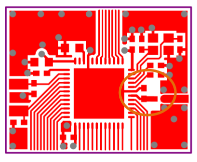
there is a keepout area. how capa gnd is connected. so the values for the inductor and capa. with different layout and no tuning->harmonics etc. -
Great project!
Have you released software for the board?
Are there pins on the board to flash the uC?[ ],
Renato.
@renatocan said in 💬 EFEKTA nRF5 Motion sensor:
Great project!
Have you released software for the board?
Are there pins on the board to flash the uC?[ ],
Renato.
Added test sketch with adjustable delay of response time - https://www.openhardware.io/view/642#tabs-source
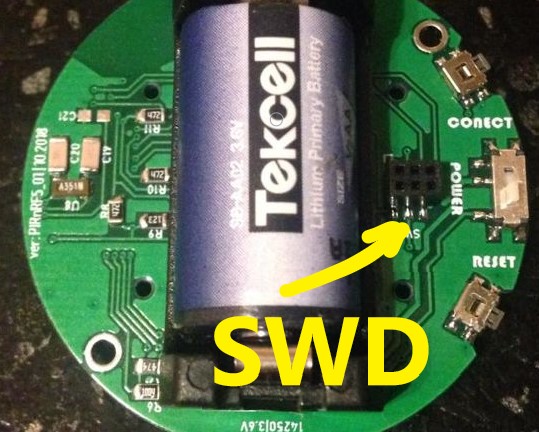
Programmable through an adapter, it always comes with the device(a little different SWD + RX TX) - https://www.openhardware.io/view/588/ICSPandFTDI-Adapter
-
Thank you very much @berkseo. Can you release the schematics and PCB layout files? I am working on a workspace analytics application in which I have to monitor several office desks to log utilization. I've already deployed a poc using mysensors hardware assembled using jump wires. Now we're looking for a more robust implementation and I think your project may be a great solution. Do you have resources related to this project published somewhere else? Or are you just using Openhardware.io?
[ ],
Renato.
Hello! It looks like you're interested in this conversation, but you don't have an account yet.
Getting fed up of having to scroll through the same posts each visit? When you register for an account, you'll always come back to exactly where you were before, and choose to be notified of new replies (either via email, or push notification). You'll also be able to save bookmarks and upvote posts to show your appreciation to other community members.
With your input, this post could be even better 💗
Register Login