Skip to content
  • MySensors
  • OpenHardware.io
  • Categories
  • Recent
  • Tags
  • Popular
Skins
  • Light
  • Brite
  • Cerulean
  • Cosmo
  • Flatly
  • Journal
  • Litera
  • Lumen
  • Lux
  • Materia
  • Minty
  • Morph
  • Pulse
  • Sandstone
  • Simplex
  • Sketchy
  • Spacelab
  • United
  • Yeti
  • Zephyr
  • Dark
  • Cyborg
  • Darkly
  • Quartz
  • Slate
  • Solar
  • Superhero
  • Vapor

  • Default (No Skin)
  • No Skin
Collapse
Brand Logo
A

akamap

@akamap
About
Posts
8
Topics
2
Shares
0
Groups
0
Followers
0
Following
0

Posts

Recent Best Controversial

  • 💬 Easy/Newbie PCB for MySensors
    A akamap

    EDIT : Seeing the pictures this big, I think I know why and it is my fault. I tried to save energy by desoldering the led on the arduino. I followed a post here on mysensors.org. But I just realized I might have desoldered the wrong thing on this arduino. I'm not sure what I desoldered, but it might be what is causing the problems (I desoldered the tiny thing below the led) I'll put a fresh one to see if this is working.

    Thanks

    Original response :

    Ok, thank for all the answers and here is more information.

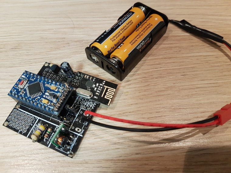
    I power it via 2AA battery. I did put a jumper on the battery point. And I am using a pro mini 3.3v (Cheap chinese clone). I am using a step up regulator to step it up to 3.3v for the arduino.

    I measured the voltages and they are as follow :

    Without USB programmer (Not working) :
    Battery : 3.00V
    Input step up : 3.00V
    Output Step UP : 3.35V
    VCC and GND on arduino : 3.34V
    VCC and GND on Radio : 3.01V

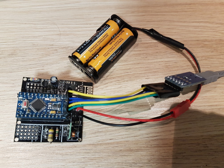
    With the USB programmer pluggued in (Working) :
    Battery : 3.00V
    Input step up : 3.00V
    Output Step UP : 3.47V
    VCC and GND on arduino : 3.48V
    VCC and GND on Radio : 3.00V

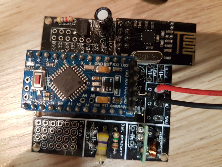
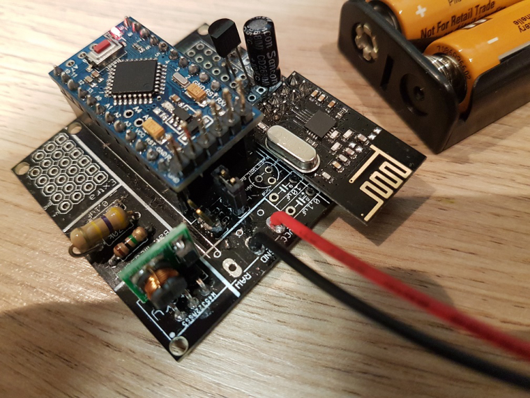
    Another information, I did not solder directly the arduino pro mini (you will see on the pictures). I don't know what the are called but I'll call them "extender". I use them so I can unplug the arduino in case I fried the pro mini.

    Here are some pictures with and without the usb programmer plugged in :

    3_1515614804192_20180110_145714.jpg

    2_1515614804191_20180110_145654.jpg

    1_1515614804191_20180110_145643.jpg

    0_1515614804191_20180110_145634.jpg

    OpenHardware.io mysensors battery easy newbie pcb mysx

  • 💬 Easy/Newbie PCB for MySensors
    A akamap

    Thank you everyone. Everythings seems to be working now. I did solder a capacitor on the booster.

    But I don't think this was all that was bad. I also find out that when I touched the capacitor for the radio, I was having mixed result. So I soldered the capacitor directly on the radio.

    Now, everything works fine. I guess I burned the trace or something was creating a short with this part.

    I just need to remove the voltage regulator as suggested by gohan now and I can start testing my battery life.

    Thanks again. Great library, great forum but most of all, great community.

    OpenHardware.io mysensors battery easy newbie pcb mysx
  • Login

  • Don't have an account? Register

  • Login or register to search.
  • First post
    Last post
0
  • MySensors
  • OpenHardware.io
  • Categories
  • Recent
  • Tags
  • Popular