Thanks to both of you. I did solder it back. I will replace them just to be sure.
A
akamap
@akamap
Posts
-
Question about capacitor -
Question about capacitorHi, I'm not sure if troubleshooting forum is the right place as this is just a question. If not, please tell me.
So I just found out an error with some of my temperature node.
I did solder the capacitor backward on the radio.Node were working great and nothing exploded.
I noticed it when I "copied" one I have to create another one.I soldered them in the right direction now, so I guess everything is right now.
But my question is : should it have exploded ? From what I know and read about capacitor is that if they are wired backwards, the will blow up. I've been using this sensor from at least 2 months now.
Is it because is such a low voltage ?
Thank you
-
💬 Easy/Newbie PCB for MySensorsThank you everyone. Everythings seems to be working now. I did solder a capacitor on the booster.
But I don't think this was all that was bad. I also find out that when I touched the capacitor for the radio, I was having mixed result. So I soldered the capacitor directly on the radio.
Now, everything works fine. I guess I burned the trace or something was creating a short with this part.
I just need to remove the voltage regulator as suggested by gohan now and I can start testing my battery life.
Thanks again. Great library, great forum but most of all, great community.
-
💬 Easy/Newbie PCB for MySensorsEDIT : Seeing the pictures this big, I think I know why and it is my fault. I tried to save energy by desoldering the led on the arduino. I followed a post here on mysensors.org. But I just realized I might have desoldered the wrong thing on this arduino. I'm not sure what I desoldered, but it might be what is causing the problems (I desoldered the tiny thing below the led) I'll put a fresh one to see if this is working.
Thanks
Original response :
Ok, thank for all the answers and here is more information.
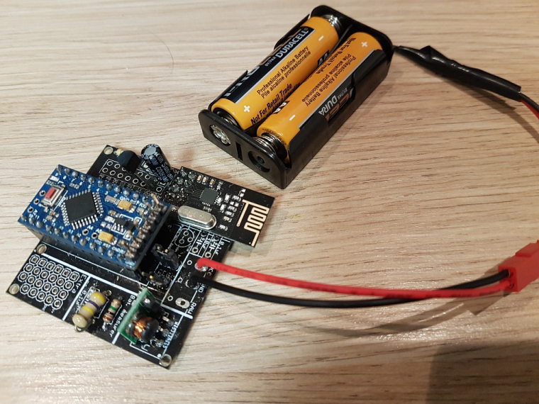
I power it via 2AA battery. I did put a jumper on the battery point. And I am using a pro mini 3.3v (Cheap chinese clone). I am using a step up regulator to step it up to 3.3v for the arduino.
I measured the voltages and they are as follow :
Without USB programmer (Not working) :
Battery : 3.00V
Input step up : 3.00V
Output Step UP : 3.35V
VCC and GND on arduino : 3.34V
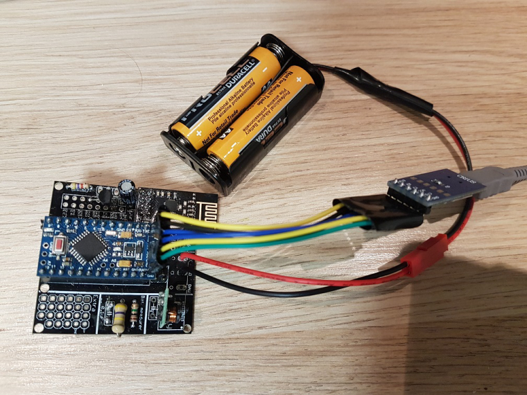
VCC and GND on Radio : 3.01VWith the USB programmer pluggued in (Working) :
Battery : 3.00V
Input step up : 3.00V
Output Step UP : 3.47V
VCC and GND on arduino : 3.48V
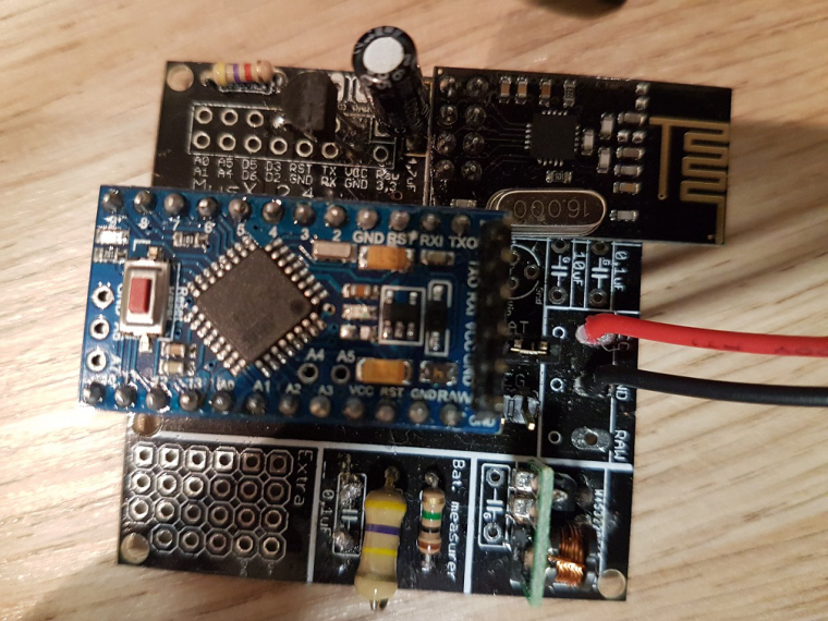
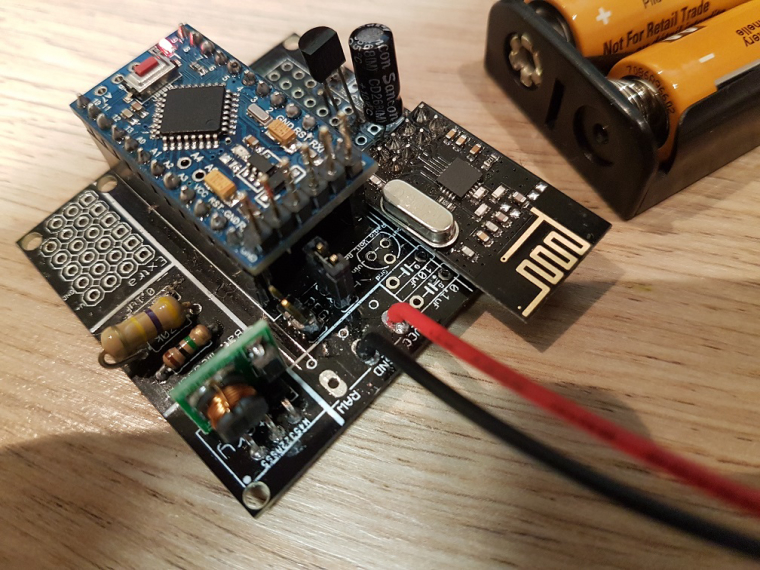
VCC and GND on Radio : 3.00VAnother information, I did not solder directly the arduino pro mini (you will see on the pictures). I don't know what the are called but I'll call them "extender". I use them so I can unplug the arduino in case I fried the pro mini.
Here are some pictures with and without the usb programmer plugged in :
-
💬 Easy/Newbie PCB for MySensorsHi everybody. Finally got my newb pcb and I soldered everything needed for the pro mini 3.3v. But I ran into problems.
I think it's the cheap chinese pdo mini but I want to ask you guys. Problem id that my node doesn't work. But when I debug my node I plug my pro mini in my computer's usb and then it works.
What I could see is that when it is battery operated I can read a 3.3v value on the vcc pin of the pro mini. When I also connect via usb this value is about 3.5v.
Could it be that my pro mini requires 3.5v.
I did solder the capacitor for the radio and i'm using a 3.3v step up converter also.Thank you
-
[RESOLVED] I'm new to this. Cannot do a simple gateway.I can confirm that my arduino nano is working now.
So what seems to be correcting my issu is using the Mysensors 2.2.0-beta librairies.
Last question :
Do I need a controller to test a complete setup with a gateway and 2 or 3 sensors ? -
[RESOLVED] I'm new to this. Cannot do a simple gateway.I was already using a capacitor. a 4.7uF 50V one.
I double check the connection and everything was correct.
I think the capacitor was not completely making connection because now, I pushed it all the way in the female connector and it seems to be working.
Or it's the 2.2.0-beta mysensors library that changed something.The first time, it worked great on the first try.
I powered it off and tried a second time. This time, it seemed to have initialized transport on the second try.
connected with VIDEOTRON1198, channel 11
dhcp client start...
0;255;3;0;9;!TSM:INIT:TSP FAIL
0;255;3;0;9;TSM:FAIL:CNT=1
0;255;3;0;9;TSM:FAIL:PDT
ip:192.168.0.120,mask:255.255.255.0,gw:192.168.0.1
pm open,type:2 0
0;255;3;0;9;TSM:FAIL:RE-INIT
0;255;3;0;9;TSM:INIT
0;255;3;0;9;TSM:INIT:TSP OK
0;255;3;0;9;TSM:INIT:GW MODE
0;255;3;0;9;TSM:READY:ID=0,PAR=0,DIS=0
0;255;3;0;9;MCO:REG:NOT NEEDED
IP: 192.168.0.120
0;255;3;0;9;MCO:BGN:STP
sl
f r0, 0;255;3;0;9;MCO:BGN:INIT OK,TSP=1
scandone
usl
Do I have to check this or is it normal ?
This is with my ESP8266.
I'll try with my arduino nano now to see if it's working -
[RESOLVED] I'm new to this. Cannot do a simple gateway.I'm new with all this. I have basic programmer notion but that's about it.
I'm trying to get a setup with multiple temperature sensor for the pool and house. I found out about Mysensors on some forums and it seems great. But I can't seem to make the gateway work.
That's what I have at the moment :
I tried hooking a ESP8266 wih a NRF24L01+ radio. First I connected the radio to the ESP8266, but after a few hours of not working, I did solder everything to make sure the connection were ok (without any success)Problem I am having is that it doesn't seem to be able to initiate transport.
Here is me serial log :
0;255;3;0;9;MCO:BGN:INIT GW,CP=RNNGE--,VER=2.1.1
0;255;3;0;9;TSF:LRT:OK
0;255;3;0;9;TSM:INIT
0;255;3;0;9;TSF:WUR:MS=0
scandone
state: 0 -> 2 (b0)
state: 2 -> 3 (0)
state: 3 -> 5 (10)
add 0
aid 1
cnt

connected with VIDEOTRONXXXX, channel 11
dhcp client start...
0;255;3;0;9;!TSM:INIT:TSP FAIL
0;255;3;0;9;TSM:FAIL:CNT=1
0;255;3;0;9;TSM:FAIL:PDT
ip:192.168.0.120,mask:255.255.255.0,gw:192.168.0.1
pm open,type:2 0
0;255;3;0;9;TSM:FAIL:RE-INIT
0;255;3;0;9;TSM:INIT
0;255;3;0;9;!TSM:INIT:TSP FAIL
0;255;3;0;9;TSM:FAIL:CNT=2
0;255;3;0;9;TSM:FAIL:PDT
I also tried doing a serial gateway with an arduino nano, but seems the errors are the same.
After reading a couple of forum thread, the most commun answer to this is either "bad wiring" or "bad radio". I tried multiple radio (bought a bunch all together) and the all have the same output. And double checked the wiring (redid them more than 5 times)
I installed HomeAssistant, but did no configuration since the gateway doesn't seem to be working.
Do I need to have a sensor node and a working controller to test the gateway ?And I read that there are "cheap" radio clone out there and it seems that's what I got. Could this be the problem ? This is what I got : https://www.amazon.ca/gp/product/B01C3YNGI8/ref=oh_aui_detailpage_o00_s00?ie=UTF8&th=1 Notice that the ground doesn't have the white square around it.
I'm using the latest Mysensor library from github and the latest Arduino IDE.
And sorry for my english, not my first langage.
Thank you