Navigation

    • Register
    • Login
    • OpenHardware.io
    • Categories
    • Recent
    • Tags
    • Popular
    1. Home
    2. Bandra
    3. Best
    • Profile
    • Following
    • Followers
    • Topics
    • Posts
    • Best
    • Groups

    Best posts made by Bandra

    • RE: My Ideal sensor node PCB

      Thanks for your interest, guys!

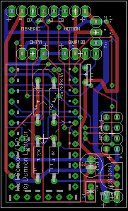
      My PCB is getting really close, but I'm not entirely happy with it. I've made up 5 of them and scattered them around my place. For the most part, they're working well. However I have the following issues:

      • The battery voltage varies. I don't think my cap is quite doing the job, so I may need to tweak the PCB to get it closer to the voltage divider. I'm running Domoticz and it does a good job of averaging the battery level out, so it's not completely bad, but I'd really like to fix it in the next version of the PCB.
      • My moisture sensor (the one from the MySensors store) doesn't work very well. It chews the battery (cos the sensor from the store has 2 leds on it, plus it's always "on". I'll pop those off and see how it goes. However I think I can do the moisture sensor better. I'm thinking of including another voltage divider, and run the sensor off the digital pin for power. That way, I can power the sensor down in between samples.

      I think that I can also include my own step up voltage converter. I'm not entirely happy with the chinese step up converter. So far my 2xAA batteries have lasted several weeks, and they're still going strong, but I suspect that I'll only get a few months out of them. I'm aiming for a year.

      I'm designing our new house at the moment, which is taking up a lot of time, but I'll get onto rev 2 shortly. Once I'm happy with it, I'll put the design up here so that you guys can get your own made up.

      posted in Hardware
      Bandra
      Bandra
    • RE: My Ideal sensor node PCB

      I've just sent my PCB off for manufacturing. My design spec was pretty close to your requirements. It looks like this:
      multisensor-image.png

      It's 5x3cm. I've panelised it so that I fit 3 across on a 5x10 board. Total cost for 30 boards from itead is $20. It's 5x3 because that's the size of a double AA battery holder. So I'll have two options: either hot-glue it onto the top of the battery holder, or mount it beside a battery holder (making a total footprint of 5x6) which will half the height to fit into most plastic cases.

      It supports the 3.3v and 5v pro minis, with access to A5 and A6. It uses the space underneath the APM for the 4 resistors on the board (voltage divider plus others).

      It has a socket for the nRF24L01+. It doesn't hang over the edge, it actually hangs over the APM. My spaghetti board prototype showed no problems with this configuration. It makes it much more compact.

      It has space for a DHT-11 and a BMP180 for pressure. It has space for the 3.3v step-up converter. It has a DS1820 onboard and also a photoresistor light cell. It then breaks out several pins for motion, soil moisture and distance sensors. The "generic" breakout exposes Vcc, Gnd, D7, D8 and A2.

      All in all, it provides support for all my standard configurations, which are:

      • All sensors have light, temp and motion on board
      • Configuration A: Humidity (DHT-11)
      • Configuration B: Humidity (DHT-11) and baro pressure (bmp180)
      • Configuration 😄 Door reed switch
      • Configuration 😧 Distance
      • Configuration E: Soil moisture

      Based on the conversations recently about the inefficiency of the step-up converter, I'm yet to decide whether I'll make my own step-up converter board that fits in the same slot on my PCB, or whether I'll create v2 that scraps the step-up and uses the XC9140A331 or something else onboard.

      posted in Hardware
      Bandra
      Bandra
    • RE: My Ideal sensor node PCB

      @ServiceXp
      Thanks mate! I've soldered up 3 of the boards now and they're all working fine.

      So far I've made one just with temp and light. One with temp, light and humidity, and one with temp, light, humidity and pressure. I'll make one more tonight that will just have temp and soil moisture.

      I'm not entirely happy with the two caps at the bottom of the board. The auto-route feature of Eagle is good, but I don't think it quite got that right. Seems to run fine without the two caps so the PCBs are not a write-off.

      I've got way more boards than I need. So I'm happy to send 3 off to you. PM me your address.

      posted in Hardware
      Bandra
      Bandra
    • RE: My Ideal sensor node PCB

      Oh yeah, I'm also scouting around for a nice enclosure that will snugly fit the PCB and 2xAA battery holder side-by-side (around 60mmx 60mm) and with room for the PIR motion sensor sitting on top of those. Haven't found anything yet. I may have to buy a 3d printer to make my own... 🙂

      posted in Hardware
      Bandra
      Bandra