@ServiceXp
My PCBs are winging their way to you (sorry, got forgot to send them for a week or two). They may solve your problem. Let me know when you get them.
@ServiceXp
My PCBs are winging their way to you (sorry, got forgot to send them for a week or two). They may solve your problem. Let me know when you get them.
Oh yeah, I'm also scouting around for a nice enclosure that will snugly fit the PCB and 2xAA battery holder side-by-side (around 60mmx 60mm) and with room for the PIR motion sensor sitting on top of those. Haven't found anything yet. I may have to buy a 3d printer to make my own... :)
Thanks for your interest, guys!
My PCB is getting really close, but I'm not entirely happy with it. I've made up 5 of them and scattered them around my place. For the most part, they're working well. However I have the following issues:
I think that I can also include my own step up voltage converter. I'm not entirely happy with the chinese step up converter. So far my 2xAA batteries have lasted several weeks, and they're still going strong, but I suspect that I'll only get a few months out of them. I'm aiming for a year.
I'm designing our new house at the moment, which is taking up a lot of time, but I'll get onto rev 2 shortly. Once I'm happy with it, I'll put the design up here so that you guys can get your own made up.
Ok, back from meeting.
So, for sketches that don't need to sleep on interrupt, then things are ok because I can code around it like this:
if ((unsigned long)(millis() - timeOfLastSensorSend) >= MIN_SAMPLING_INTERVAL) {
    // read sensors and send to gateway
    timeOfLastSensorSend = millis();
}
gw.sleep(SLEEP_TIME);
timeOfLastSensorSend -= SLEEP_TIME;
My rationale here is that if millis doesn't increment then I should make my variable decrement by the same amount. Same effect.
However, the catch is when sleeping with interrupt. My thinking was to modify MySensors.cpp to change the return value of sleep. Something like this:
unsigned long MySensor::internalSleep(unsigned long ms) {
    unsigned long origMs = ms;
    while (continueTimer && ms >= 8000) { LowPower.powerDown(SLEEP_8S, ADC_OFF, BOD_OFF); ms -= 8000; }
    if (continueTimer && ms >= 4000)    { LowPower.powerDown(SLEEP_4S, ADC_OFF, BOD_OFF); ms -= 4000; }
    ...
    if (continueTimer && ms >= 16)      { LowPower.powerDown(SLEEP_15Ms, ADC_OFF, BOD_OFF); ms -= 15; }
    return (origMs - ms);
}

unsigned long MySensor::sleep(unsigned long ms) {
    // Let serial prints finish (debug, log etc)
    Serial.flush();
    RF24::powerDown();
    continueTimer = true;
    return internalSleep(ms);
}

unsigned long MySensor::sleep(int interrupt, int mode, unsigned long  ms) {
    // Let serial prints finish (debug, log etc)
    unsigned long sleptFor = 0;
    Serial.flush();
    RF24::powerDown();
    attachInterrupt(interrupt, wakeUp, mode); //Interrupt on pin 3 for any change in solar power
    if (ms>0) {
            continueTimer = true;
            sleptFor = sleep(ms);
    } else {
            Serial.flush();
            LowPower.powerDown(SLEEP_FOREVER, ADC_OFF, BOD_OFF);
    }
    detachInterrupt(interrupt);
    return sleptFor;
}
So rather than return a boolean on sleep(x,y,z), return the amount of time it slept for before it was interrupted. The check of the boolean is replaced with a check if return code > 0.
Hopefully my ramblings make some kind of sense.
@John
Your project looks great! I'm looking around for an home automation controller and was tossing between domoticz, openhab and FHEM.
My criteria are:
May have to add yours to the mix to trial.
How difficult would it be to compile openzwave and integrate it by some mechanism to PiDome, do you think?
@hek
I'd like to ask for a small change to be made to the sleep function.
When we call gw.sleep(x) or gw.sleep(x,y,z) then the arduino disables the interrupt timer (to save power) that triggers the counter that drives millis(). So the value returned from millis() stalls when we sleep.
This is ok on our battery powered devices, since it's saving power, but makes it hard to determine how long it's been since we sent values to the gateway.
For example, if I use this code:
if ((unsigned long)(millis() - timeOfLastSensorSend) >= MIN_SAMPLING_INTERVAL) {
    // read sensors and send to gateway
    timeOfLastSensorSend = millis();
}
gw.sleep(SLEEP_TIME);
Then it doesn't work because millis() does not increment while the the sketch is asleep.
I have a thought on how we can solve this but I have a to get to a work meeting.
Thanks @Yveaux
I think I'm pretty safe there because I'm relying on the MySensors library to do the interrupt [ie, the sleep(int, int, long) method]. In that method, the library disables the interrupt itself [in MySensor::sleep it performs a "detachInterrupt(interrupt);" ]
I got it going reasonably well by doing two things. I moved the code that tests the D3 pin towards the beginning of the loop(). This helps avoid flapping (ie, if the pin fell low between the time the the interrupt was triggered to the end of the next loop() then it might cause flapping). I also changed my sleep call from:
sleep(INTERRUPT, CHANGE, 30000)
to
sleep(INTERRUPT, RISING, 30000)
This way, a flapping motion sensor doesn't affect me as much. Those two changes worked a treat. My multisensor sketch works well now!
Thanks again for all your advice on this forum.
@Yveaux
True. The library is changing constantly (for the better!).
I've not encountered any major bugs in the 1.4 beta libraries that I've tried. So if the OP was just starting out then there's value in pulling down the latest 1.4 (which should be quite stable) and starting their sketches from there. Once 1.4 goes to production, then upgrading sketches will be much easier from 1.4b -> 1.4 than from 1.3 -> 1.4.
I'm coming close to finalising my multisensor sketch. I'll post code once I clean it up a little. I have a newborn at home, so if I forget to put code here then somebody please remind me in a little while :)
My ipad doesn't have a "valid" browser. Which means that I can't scroll inside the code box to even read the code :(
@hek thanks for putting that together.
I'm designing my new house at the moment and have planned to have a custom arduino-driven RFID reader at the front door. I was debating including it into the mysensors network.
My current line of thinking is to connect it to my LAN and have it make a call back to the controlling system (Vera?). The controller has the list of valid cards and it then calls to the z-wave lock to tell it to disengage.
There's two reasons doing it this way. It keeps the valid/invalid logic off the RFID arduino, making it harder for attackers to compromise the system. Also, the mysensors wireless network is not secure. Finally, it also makes it easier to program new cards, since I don't have to put a new sketch onto the RFID reader.
However, I was thinking about making it easier to build anciliary systems, such as shed door, front gate, etc, and this sketch would be perfect.
@warawara , the development branch is very stable. At this point there is no reason not to use it. It is superior in every way to 1.3.
Moved my solder point to the H pad. Also bridged the H pad with centre pad. All works now. Thanks everyone!
Interesting observation. The motion sketch works very well. But when I try my multisensor sketch it always reads high and keeps triggering. Must be a problem with taking too long in the interrupt. I recall a small discussion about that. Time for some searching...
@marceltrapman
The auto-route feature in Eagle attempts to make the most efficient board layout it can. To do that, it seems to join the traces where ever it can. When you click on the rats nest button, it will combine any GND traces that it can. Since the cap sits on GND, for example, it assumes it can put it anywhere on a GND trace, and physically dislocates it from the radio pins. I just noticed that on my board, for example, the nRF24 cap doesn't sit directly across + and -.
So my next go I would manually route those traces first then auto-route the rest.
It's no big deal, because if I get bad reception then I can always solder the decoupling cap directly onto the radio.
I did choose the option to check my board. It's my very first PCB (which is why I didn't pick up the problem) so I was expecting for them to find lots of problems. But it turns out that technically my board is correct. It's the "logic" of the board that's wrong, so iTead could not have picked this up.
Lesson learned!
@ServiceXp
Thanks mate! I've soldered up 3 of the boards now and they're all working fine.
So far I've made one just with temp and light. One with temp, light and humidity, and one with temp, light, humidity and pressure. I'll make one more tonight that will just have temp and soil moisture.
I'm not entirely happy with the two caps at the bottom of the board. The auto-route feature of Eagle is good, but I don't think it quite got that right. Seems to run fine without the two caps so the PCBs are not a write-off.
I've got way more boards than I need. So I'm happy to send 3 off to you. PM me your address.
Hah! I am at this very stage right now. Finding the right enclosure is HARD!
Ideally I want a vented enclosure so temp, humidity, pressure all work. Seems like all of the boxes on fleabay are waterproof, not vented.
In your sketch you may just be sleeping on a timer. Ie:
gw.sleep(SLEEP_TIME);
With the 1.4 beta improvements, there's now provision to sleep on timer AND on interrupt. Like this:
#define DIGITAL_INPUT_SENSOR 3   // D3 is the only interrupt pin left (radio uses D2)
#define INTERRUPT DIGITAL_INPUT_SENSOR-2
unsigned long SLEEP_TIME = 30000;

void setup() {
  pinMode(DIGITAL_INPUT_SENSOR, INPUT);      // sets the digital pin as input
}

void loop() {
    ...
    gw.sleep(INTERRUPT,CHANGE, SLEEP_TIME);
}
That may not all be exactly right, but it should be pretty close.
Yeah, the sketch I found waits for it to warm up. I'll increase the warmup period and try again. Thanks for the suggestion!
Just for completeness, my PCBs came in and I've had a chance to solder them up. The PCBs are really nice. iTead have done a great job. @Zeph, turns out that I didn't need to cut my PCBs because the friendly folk at iTead cut them for me.
Here's a photo of a few things soldered on:
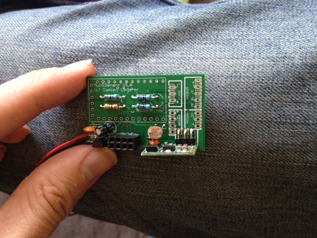
Underneath the APM I have a 1M and 470K resistors for the battery voltage check. There's also a 4.7K resistor for the Dallas DS18B20 temp sensor. Finally there's a 4.7K resistor for the LDR divider circuit.
You can also see the 4x2 header for the radio, the LDR itself, and the 3.3v step-up converter.
Here's the (almost) finished package:
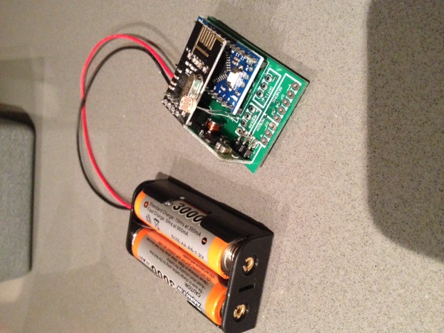
You can see all the exposed solder pads for my various sensor configurations (motion, humidity, baro pressure, door reed switch, distance and soil moisture).
The range on the nRF24 is fine. I put my gateway at one end of the apartment and it easily picked up my sensor at the other end of the apartment (about 10m away through two thick internal walls). So I'm not worried about the nRF24 being parallel to the GND plane.
I actually took off the 4.7uF cap. It's probably my PCB (don't think the auto-route did a great job of it) but it made the radio flaky. Works just fine without it.
Now to find a box to put it in...
Thanks for the replies, @lininger and @Yveaux. Do you bridge H and the centre solder pad?
Here's my solder effort:
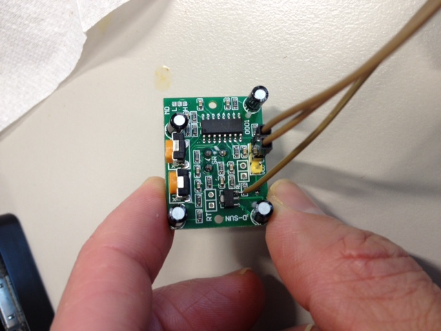
I checked with my multimeter, and soldering a 3.3v wire onto the 7133 leg gets 3.3v to the H solder pad. So I'm pretty sure that I've done the equivalent of yours.
And yet, it doesn't seem to work. After a few seconds my output pin just goes high and never drops low. I've tried to tune the pots but it makes little difference.
Just wanted to check that at least I got the power right. Thanks guys!