I've uploaded our Eagle PCB files as well as a few PDFs/PNGs of the schematic/layout for quick viewing.
Thanks for the tip on the other nRF24 board to try.
I've uploaded our Eagle PCB files as well as a few PDFs/PNGs of the schematic/layout for quick viewing.
Thanks for the tip on the other nRF24 board to try.
@yveaux I would be happy to provide our schematic and layout details if you think it would be helpful in identifying the hardware design flaw we made. If there is something we could do to fix this with a board change, that would be interesting to know/consider. (Especially if it ends up being mistake that is commonly made by others using who are also using the nRF24 Board).
Alternatively, it could be an issue with our specific nRF24L01+ boards. While we did order some from Amazon and some from AliExpress, out best guess is that they are all counterfeit/clones. If you know of a source where we could order a board that in confidently authentic, that would be an interesting experiment as well.
@mfalkvidd Hello! I am one of the other "we" mentioned in this post. I don't have access to the layout files at this moment, but I checked the Gerber files and none of the SPI lines are routed under (or near) the antenna. They are also not routed near any other lines that route under the antenna.
"The placement of the nrf's antenna on the board is very unusual." Bad
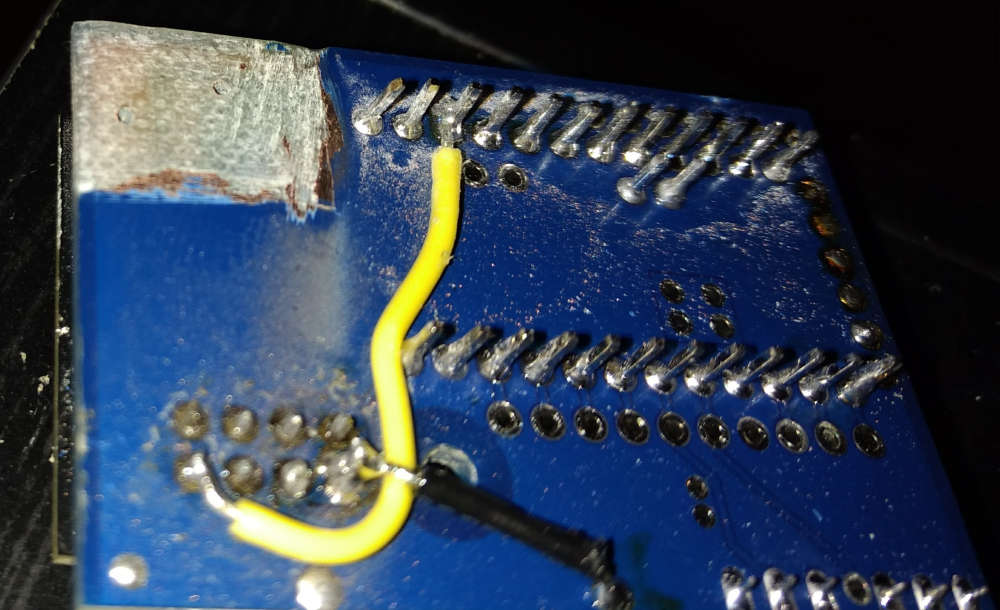
Yeah..... In our original goal/planning for this sensor board, we were going for a tight footprint that would sit inside a 3D printed enclosure easily and didn't think about the antenna being parallel to the PCB underneath it. Once we started having issues, we used a dremel to remove all the copper we could from the board below the antenna, but that didn't change the behavior we saw.
Technically, we did that dremel experiment on a different board (we made two different designs) that was showing the same issue. Below, you can see an image of that experiment.
