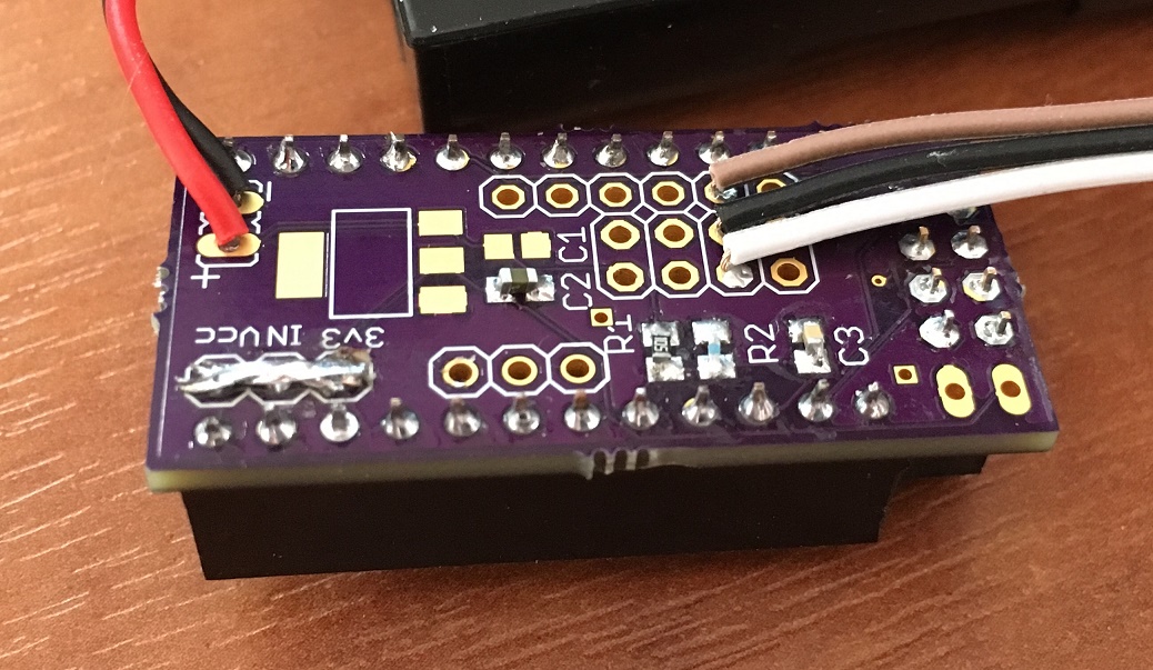
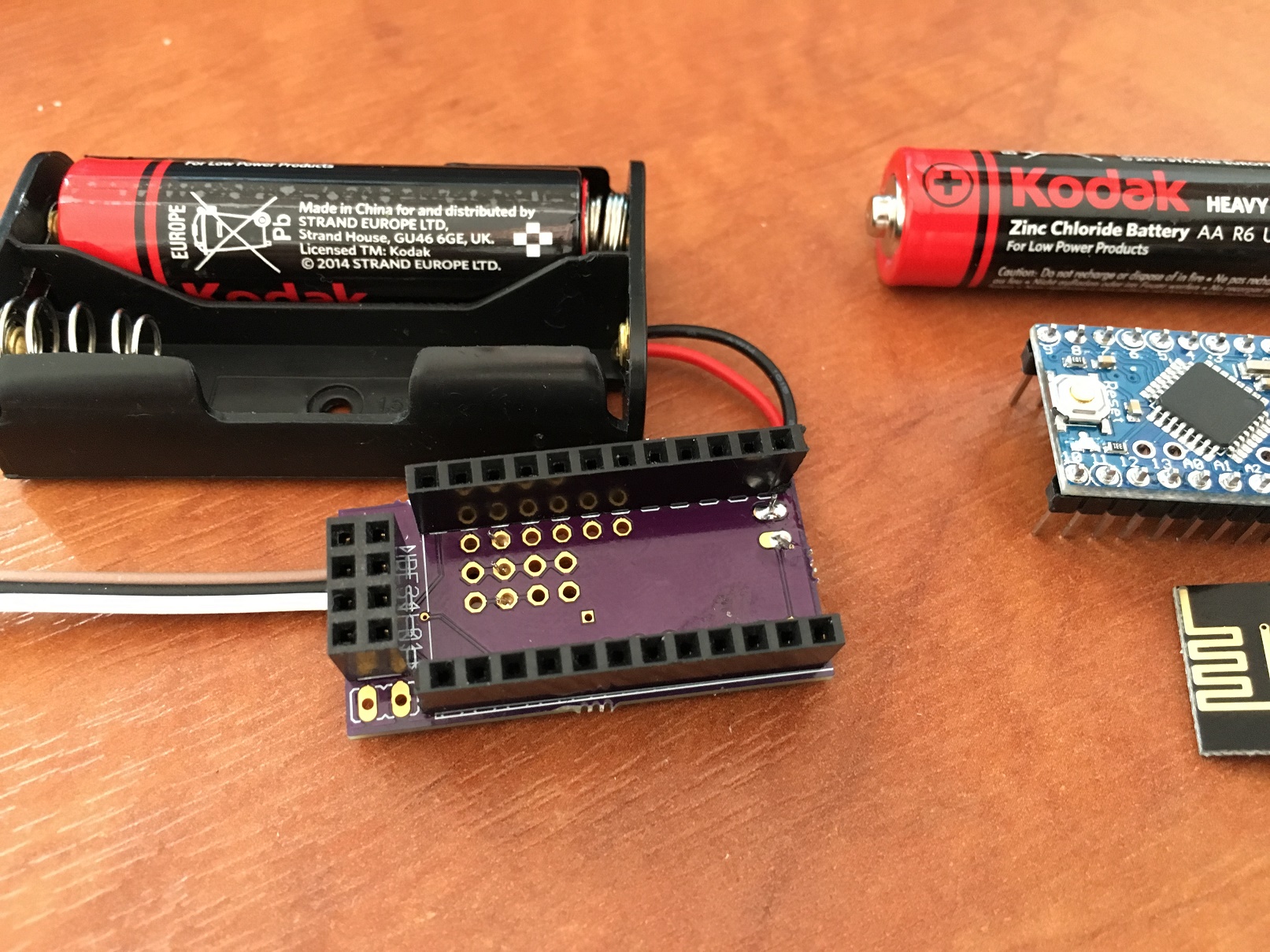
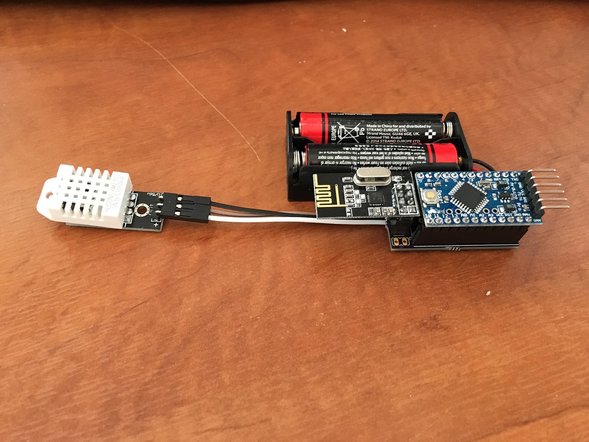
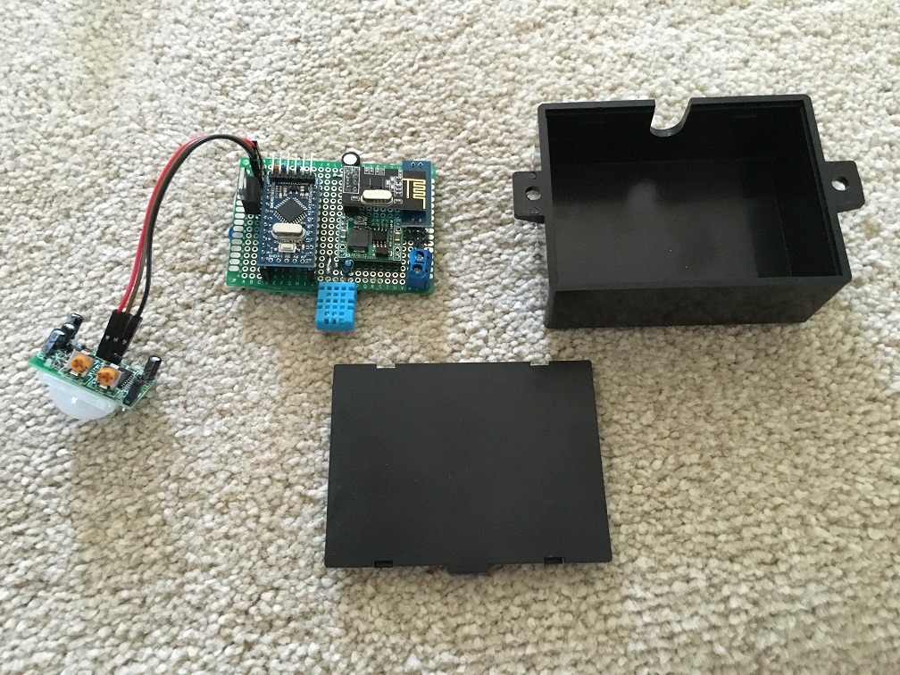
I've mashed together a few sketches to create a kind of security light. I've not put any logic for when the light should come on in the sketch and instead let my Domoticz controller decide when and what intensity the light should come on. In this way i have it set to a very low level of around %15 from 30minutes after sunset till around 11 but if motion is detected i bump it up to %75 for 1 minute. I've done it this way as i can control it remotely and also modify the delay/intensity etc without having to open up the case. I'm also sensing the battery voltage of a 12v battery. I'm using a 1M and 470k resistor although i had to play with the resistor values, the 470k one in particular in the code to get it to be accurate. I am sending the temp every 2 mins and the battery voltage every 5 mins using a timer and the main loop monitors the motion sensor and sends that it's been triggered otherwise it just loops around again. I had looked at interrupts and sleeping inbetwen but then i couldn't see a way to control it remotely as Domoticz wouldn't know when it was awake. It seems to be working ok for me so hope it helps some people.
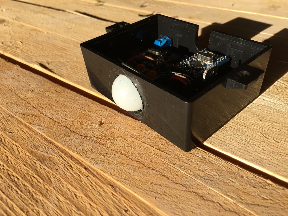
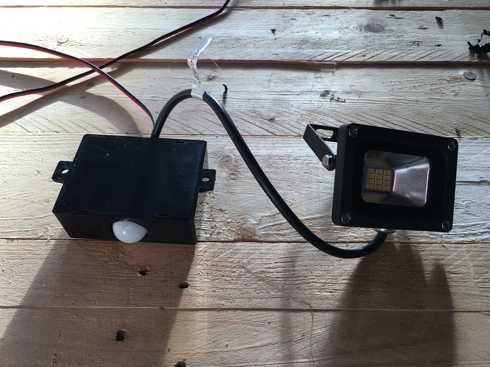
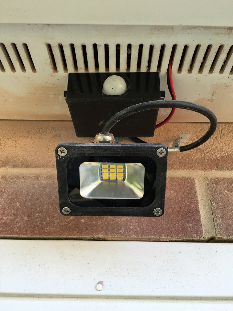
I housed it all in a small project box which is secured to the underside of my garage and the light then connects directly to the circuit. If anyone is interested in a fritzing diagram then please let me know.
/**
 * The MySensors Arduino library handles the wireless radio link and protocol
 * between your home built sensors/actuators and HA controller of choice.
 * The sensors forms a self healing radio network with optional repeaters. Each
 * repeater and gateway builds a routing tables in EEPROM which keeps track of the
 * network topology allowing messages to be routed to nodes.
 *
 * Created by Henrik Ekblad <henrik.ekblad@mysensors.org>
 * Copyright (C) 2013-2015 Sensnology AB
 * Full contributor list: https://github.com/mysensors/Arduino/graphs/contributors
 *
 * Documentation: http://www.mysensors.org
 * Support Forum: http://forum.mysensors.org
 *
 * This program is free software; you can redistribute it and/or
 * modify it under the terms of the GNU General Public License
 * version 2 as published by the Free Software Foundation.
 *
 *******************************

 *
 * DESCRIPTION
 * This sketch provides a Dimmable LED Light along with Temp/Humidity/voltage sensing as well as Motion sensing.
 */

#define SN "SecurityLED"
#define SV "1.2"
#define CHILD_ID_HUM 0
#define CHILD_ID_TEMP 1
#define CHILD_ID_VOLTAGE 2
#define CHILD_ID_PIR 3

#define HUMIDITY_SENSOR_DIGITAL_PIN 6
#define DIGITAL_INPUT_SENSOR 3   // The digital input you attached your motion sensor.
#define INTERRUPT DIGITAL_INPUT_SENSOR-2 // Usually the interrupt = pin -2 (on uno/nano anyway)

#include <MySensor.h>
#include <SPI.h>
#include <DHT.h>
#include <SimpleTimer.h>

// the timer object
SimpleTimer timer;

#define LED_PIN 5      // Arduino pin attached to MOSFET Gate pin
//#define
int FADE_DELAY=50;  // Delay in ms for each percentage fade up/down (10ms = 1s full-range dim)

MySensor gw;

DHT dht;
float lastTemp;
boolean metric = true;
float lastHum;
float lastVolt;
int oldBatteryPcnt = 0;
int analogInput = A0;
float vout = 0.0;
float vin = 0.0;
int value = 0;
float R1 = 1000000.0;
float R2 = 454500.0;
boolean sensordelay;

static int currentLevel = 0;  // Current dim level...
MyMessage dimmerMsg(0, V_DIMMER);
MyMessage lightMsg(0, V_LIGHT);
MyMessage msgHum(CHILD_ID_HUM, V_HUM);
MyMessage msgTemp(CHILD_ID_TEMP, V_TEMP);
MyMessage msgVolt(CHILD_ID_VOLTAGE, V_VOLTAGE);
MyMessage msg(CHILD_ID_PIR, V_TRIPPED);

/***
 * Dimmable LED initialization method
 */
void setup()
{
  Serial.println( SN );
  gw.begin( incomingMessage );
  dht.setup(HUMIDITY_SENSOR_DIGITAL_PIN);

  pinMode(DIGITAL_INPUT_SENSOR, INPUT);      // sets the motion sensor digital pin as input
  // Register the LED Dimmable Light with the gateway
  gw.present( 0, S_DIMMER );

  gw.sendSketchInfo(SN, SV);
  // Pull the gateway's current dim level - restore light level upon sendor node power-up
  //gw.request( 0, V_DIMMER );
  gw.present(CHILD_ID_HUM, S_HUM);
  gw.present(CHILD_ID_TEMP, S_TEMP);
  gw.present(CHILD_ID_VOLTAGE, V_VOLTAGE);
  gw.present(CHILD_ID_PIR, S_MOTION);

  pinMode(analogInput, INPUT);
  timer.setInterval(120000,readTempHum);  // Send Temp every 2 mins
  timer.setInterval(300000,measureBattery);  // Send voltage every 5 mins
  fadeToLevel( 0 );
  readTempHum();
  measureBattery();
  sensordelay=0;
}

void ResetTripped(){
      sensordelay=0;
      FADE_DELAY=50;
}

/***
 *  Main processing loop
 */
void loop()
{
  gw.process();

  // Read digital motion value
  boolean tripped = digitalRead(DIGITAL_INPUT_SENSOR) == HIGH;
  if (tripped ==1 && sensordelay==0) {
    FADE_DELAY=0;
    Serial.print("Security Sensor state : ");
    Serial.println(tripped);
    gw.send(msg.set(tripped?"1":"0"));  // Send tripped value to gw
    tripped=0;
    gw.send(msg.set(tripped?"1":"0"));  // Send tripped value to gw
    sensordelay=1;
    timer.setTimeout(10000,ResetTripped);
  }
  timer.run();
}


void incomingMessage(const MyMessage &message) {
  if (message.type == V_LIGHT || message.type == V_DIMMER) {

    //  Retrieve the power or dim level from the incoming request message
    int requestedLevel = atoi( message.data );

    // Adjust incoming level if this is a V_LIGHT variable update [0 == off, 1 == on]
    requestedLevel *= ( message.type == V_LIGHT ? 100 : 1 );

    // Clip incoming level to valid range of 0 to 100
    requestedLevel = requestedLevel > 100 ? 100 : requestedLevel;
    requestedLevel = requestedLevel < 0   ? 0   : requestedLevel;

    Serial.print( "Changing level to " );
    Serial.print( requestedLevel );
    Serial.print( ", from " );
    Serial.println( currentLevel );

    fadeToLevel( requestedLevel );

    // Inform the gateway of the current DimmableLED's SwitchPower1 and LoadLevelStatus value...
    gw.send(lightMsg.set(currentLevel > 0 ? 1 : 0));

    // hek comment: Is this really nessesary?
    gw.send( dimmerMsg.set(currentLevel) );

    }
}

/***
 *  This method provides a graceful fade up/down effect
 */
void fadeToLevel( int toLevel ) {

  int delta = ( toLevel - currentLevel ) < 0 ? -1 : 1;

  while ( currentLevel != toLevel ) {
    currentLevel += delta;
    analogWrite( LED_PIN, (int)(currentLevel / 100. * 255) );
    delay( FADE_DELAY );
  }
}

void readTempHum() {
 delay(dht.getMinimumSamplingPeriod());
  float temperature = dht.getTemperature();
  if (isnan(temperature)) {
      Serial.println("Failed reading temperature from DHT");
  } else if (temperature != lastTemp) {
    lastTemp = temperature;
    if (!metric) {
      temperature = dht.toFahrenheit(temperature);
    }
    gw.send(msgTemp.set(temperature, 1));
    Serial.print("T: ");
    Serial.println(temperature);
  }

  float humidity = dht.getHumidity();
  if (isnan(humidity)) {
      Serial.println("Failed reading humidity from DHT");
  } else if (humidity != lastHum) {
      lastHum = humidity;
      gw.send(msgHum.set(humidity, 1));
      Serial.print("H: ");
      Serial.println(humidity);
  }
}

void measureBattery() {
   // read the value at analog input
   value = analogRead(analogInput);
   vout = (value * 5.0) / 1024.0; // see text
   vin = vout / (R2/(R1+R2));
   int batteryPcnt = value / 10;

   #ifdef DEBUG
   Serial.print("Battery Voltage: ");
   Serial.print(vin);
   Serial.println(" V");

   Serial.print("Battery percent: ");
   Serial.print(batteryPcnt);
   Serial.println(" %");
   #endif

   if (oldBatteryPcnt != batteryPcnt) {
     // Power up radio after sleep
     gw.sendBatteryLevel(batteryPcnt);
     gw.send(msgVolt.set(vin, 1));
     oldBatteryPcnt = batteryPcnt;
   }
}