@ykhokhlov would like to get it going as well, have a requirement for a tiny form factor, have had one of these in the drawer forever.
C
chickey
@chickey
Posts
-
Introducing MySensors on nRF24LE1 -
RF Nano = Nano + NRF24, for just $3,50 on AliexpressHow are people getting on with these boards, mine just arrived today so doing a bit of testing. I wanted one as a replacement gateway for home assistant. I've got it working at 1mb and the pin changes suggested above, just wondered how they worked out for people in practice over the long term.
I also wanted to mention that there is another option although it would work out more expensive
-
💬 AC-DC double solid state relay moduleIf anyone in the UK is after boards/parts i have spares.
-
Robot mower ignores the rain, MySensors to the rescue!Well i got myself a Worx Landroid 794E from ebay, just looking for a base station and boundary wire now and i'll be up and running. Did you ever sort your issue to stop it going out in the rain?
-
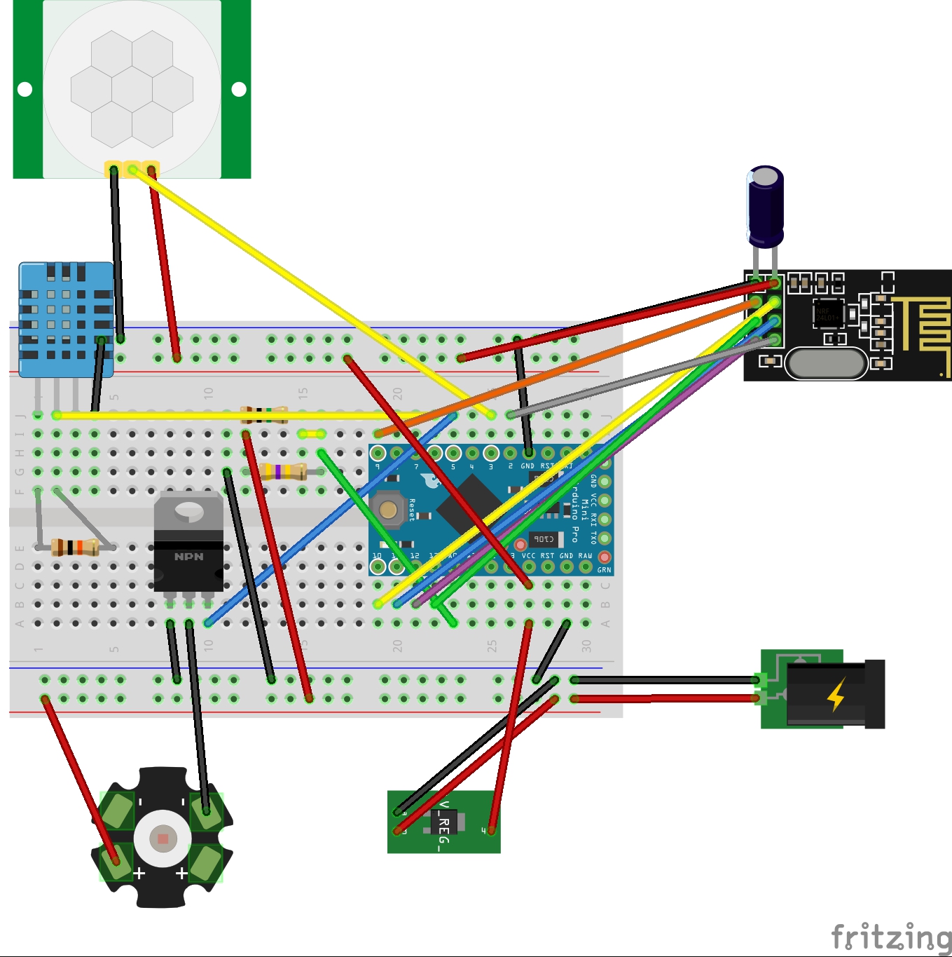
Dimable Security light with PIR/Temp/Humidity and Voltage sense.@Ashley-Savage Had a big rewrite this evening and all seems good now. If you set it to a level then switch it off the level is remembered so if you issue an on command it goes to the previous level. It seems a little bit more stable as well but i'll not know fully until i put it outside for use in the wild as it where. I'm thinking i might change the DHT11 for a Dallas sensor though as i received a few waterproof ones this week as they should be more accurate and can support negative temps which living in the UK i'll need come the autumn.
/** * The MySensors Arduino library handles the wireless radio link and protocol * between your home built sensors/actuators and HA controller of choice. * The sensors forms a self healing radio network with optional repeaters. Each * repeater and gateway builds a routing tables in EEPROM which keeps track of the * network topology allowing messages to be routed to nodes. * * Created by Henrik Ekblad <henrik.ekblad@mysensors.org> * Copyright (C) 2013-2015 Sensnology AB * Full contributor list: https://github.com/mysensors/Arduino/graphs/contributors * * Documentation: http://www.mysensors.org * Support Forum: http://forum.mysensors.org * * This program is free software; you can redistribute it and/or * modify it under the terms of the GNU General Public License * version 2 as published by the Free Software Foundation. * ******************************* * * DESCRIPTION * This sketch provides a Dimmable LED Light along with Temp/Humidity/voltage sensing as well as Motion sensing. */ #include <SPI.h> #include <MySensor.h> #include <DHT.h> #include <SimpleTimer.h> #define SN "SecurityLED" #define SV "1.3" #define CHILD_ID_LIGHT 1 #define CHILD_ID_HUM 0 #define CHILD_ID_TEMP 1 #define CHILD_ID_VOLTAGE 2 #define CHILD_ID_PIR 3 #define EPROM_LIGHT_STATE 1 #define EPROM_DIMMER_LEVEL 2 #define LIGHT_OFF 0 #define LIGHT_ON 1 #define LED_PIN 5 // Arduino pin attached to MOSFET Gate pin #define HUMIDITY_SENSOR_DIGITAL_PIN 6 #define DIGITAL_INPUT_SENSOR 3 // The digital input you attached your motion sensor. #define INTERRUPT DIGITAL_INPUT_SENSOR-2 // Usually the interrupt = pin -2 (on uno/nano anyway) #define MY_DEFAULT_TX_LED_PIN A2 #define MY_DEFAULT_RX_LED_PIN A3 #define MY_DEFAULT_ERR_LED_PIN A4 int FADE_DELAY=50; // Delay in ms for each percentage fade up/down (10ms = 1s full-range dim) // the timer object SimpleTimer timer; int LastLightState=LIGHT_OFF; int LastDimValue=100; DHT dht; float lastTemp; boolean metric = true; float lastHum; float lastVolt; int oldBatteryPcnt = 0; int analogInput = A0; float vout = 0.0; float vin = 0.0; int value = 0; float R1 = 1000000.0; float R2 = 454500.0; boolean sensordelay; MySensor gw; MyMessage lightMsg(CHILD_ID_LIGHT, V_LIGHT); MyMessage dimmerMsg(CHILD_ID_LIGHT, V_DIMMER); MyMessage msgHum(CHILD_ID_HUM, V_HUM); MyMessage msgTemp(CHILD_ID_TEMP, V_TEMP); MyMessage msgVolt(CHILD_ID_VOLTAGE, V_VOLTAGE); MyMessage msg(CHILD_ID_PIR, V_TRIPPED); void setup() { gw.begin(incomingMessage, AUTO, false); // Send the Sketch Version Information to the Gateway gw.sendSketchInfo(SN, SV); dht.setup(HUMIDITY_SENSOR_DIGITAL_PIN); pinMode(DIGITAL_INPUT_SENSOR, INPUT); // sets the motion sensor digital pin as input pinMode(analogInput, INPUT); // sets the battery voltage reading input gw.present(CHILD_ID_LIGHT, S_DIMMER ); gw.present(CHILD_ID_HUM, S_HUM); gw.present(CHILD_ID_TEMP, S_TEMP); gw.present(CHILD_ID_VOLTAGE, V_VOLTAGE); gw.present(CHILD_ID_PIR, S_MOTION); sensordelay=0; timer.setInterval(120000,readTempHum); // Send Temp every 2 mins timer.setInterval(300000,measureBattery); // Send voltage every 5 mins //Retreive our last light state from the eprom int LightState=gw.loadState(EPROM_LIGHT_STATE); if (LightState<=1) { LastLightState=LightState; int DimValue=gw.loadState(EPROM_DIMMER_LEVEL); if ((DimValue>0)&&(DimValue<=100)) { //There should be no Dim value of 0, this would mean LIGHT_OFF LastDimValue=DimValue; } } //Here you actualy switch on/off the light with the last known dim level SetCurrentState2Hardware(); Serial.println( "Node ready to receive messages..." ); } void loop() { // Process incoming messages (like config and light state from controller) gw.process(); // Read digital motion value boolean tripped = digitalRead(DIGITAL_INPUT_SENSOR) == HIGH; if (tripped ==1 && sensordelay==0) { FADE_DELAY=0; Serial.print("Security Sensor state : "); Serial.println(tripped); gw.send(msg.set(tripped?"1":"0")); // Send tripped value to gw tripped=0; gw.send(msg.set(tripped?"1":"0")); // Send tripped value to gw sensordelay=1; timer.setTimeout(10000,ResetTripped); } timer.run(); } void incomingMessage(const MyMessage &message) { if (message.type == V_LIGHT) { Serial.println( "V_LIGHT command received..." ); int lstate= atoi( message.data ); if ((lstate<0)||(lstate>1)) { Serial.println( "V_LIGHT data invalid (should be 0/1)" ); return; } LastLightState=lstate; gw.saveState(EPROM_LIGHT_STATE, LastLightState); if ((LastLightState==LIGHT_ON)&&(LastDimValue==0)) { //In the case that the Light State = On, but the dimmer value is zero, //then something (probably the controller) did something wrong, //for the Dim value to 100% LastDimValue=100; gw.saveState(EPROM_DIMMER_LEVEL, LastDimValue); } //When receiving a V_LIGHT command we switch the light between OFF and the last received dimmer value //This means if you previously set the lights dimmer value to 50%, and turn the light ON //it will do so at 50% } else if (message.type == V_DIMMER) { Serial.println( "V_DIMMER command received..." ); int dimvalue= atoi( message.data ); if ((dimvalue<0)||(dimvalue>100)) { Serial.println( "V_DIMMER data invalid (should be 0..100)" ); return; } if (dimvalue==0) { LastLightState=LIGHT_OFF; LastDimValue=0; } else { LastLightState=LIGHT_ON; LastDimValue=dimvalue; gw.saveState(EPROM_DIMMER_LEVEL, LastDimValue); } } else { Serial.println( "Invalid command received..." ); return; } Serial.println( LastDimValue ); //Here you set the actual light state/level SetCurrentState2Hardware(); } static int currentLevel = 0; // Current dim level... void fadeToLevel( int toLevel ) { int delta = ( toLevel - currentLevel ) < 0 ? -1 : 1; while ( currentLevel != toLevel ) { currentLevel += delta; analogWrite( LED_PIN, (int)(currentLevel / 100. * 255) ); delay( FADE_DELAY ); } } void SetCurrentState2Hardware() { if (LastLightState==LIGHT_OFF) { Serial.println( "Light state: OFF" ); fadeToLevel(0); } else { Serial.print( "Light state: ON, Level: " ); Serial.println( LastDimValue ); fadeToLevel( LastDimValue ); } //Send current state to the controller SendCurrentState2Controller(); } void SendCurrentState2Controller() { if ((LastLightState==LIGHT_OFF)||(LastDimValue==0)) { gw.send(dimmerMsg.set(0)); } else { gw.send(dimmerMsg.set(LastDimValue)); } } void ResetTripped(){ sensordelay=0; FADE_DELAY=50; } void readTempHum() { delay(dht.getMinimumSamplingPeriod()); float temperature = dht.getTemperature(); if (isnan(temperature)) { Serial.println("Failed reading temperature from DHT"); } else if (temperature != lastTemp) { lastTemp = temperature; if (!metric) { temperature = dht.toFahrenheit(temperature); } gw.send(msgTemp.set(temperature, 1)); Serial.print("T: "); Serial.println(temperature); } float humidity = dht.getHumidity(); if (isnan(humidity)) { Serial.println("Failed reading humidity from DHT"); } else if (humidity != lastHum) { lastHum = humidity; gw.send(msgHum.set(humidity, 1)); Serial.print("H: "); Serial.println(humidity); } } void measureBattery() { // read the value at analog input value = analogRead(analogInput); vout = (value * 5.0) / 1024.0; // see text vin = vout / (R2/(R1+R2)); int batteryPcnt = value / 10; #ifdef DEBUG Serial.print("Battery Voltage: "); Serial.print(vin); Serial.println(" V"); Serial.print("Battery percent: "); Serial.print(batteryPcnt); Serial.println(" %"); #endif if (oldBatteryPcnt != batteryPcnt) { // Power up radio after sleep gw.sendBatteryLevel(batteryPcnt); gw.send(msgVolt.set(vin, 1)); oldBatteryPcnt = batteryPcnt; } } -
Dimable Security light with PIR/Temp/Humidity and Voltage sense.@Ashley-Savage No worries, btw i made a couple of changes last time which i never mentioned. I've made it so that if the PIR is tripped it sets the fade to 0 so that if Domoticz then sets the light to on it won't gradually fade up and will come on straight away which is more the behaviour you'd want from a security light. After 10 seconds however it resets the fade back to 50 which gives a 5 second delay which means that when domoticz turns the light off after 1 minute it'll nicely fade down. It also means if your manually controlling the light it'll fade on and off nice and smoothly.
I've also just made a change today as i was lurking on the forums and read a post about pwm being flickery intermittently which i've experienced personally and it was down to TX/RX and ERR led's being set to use PIN 5 which conflicts with what were using the pin for sometimes causing flickering. It now seems to work nice and smooth every time.
I've only just a few remaining issues in that if i turn the light on rather than asking for a percentage it goes to 100% which i can see the logic to but what i'd ideally like to do is have it turn on at sunset at say %15 then turn to %100 if it's tripped then go back to %15 but it returns it to %100 because of the above%100 at one command i think, might have to put it in the blocky script but it'll be difficult as i also like it to turn off at 11pm and only come on if tripped so just used as a security light. Last issue is it refuses to respond to on/off command sometimes but you can bring it back to life by using the dimmer slider to gradually power it off then it'll respond to on/off commands again which is weird.
I think i might try the default sketch again for just the dimmer to see if i get the above behavior.
-
PWM frequencies on pin 9,10,11You my friend are a genius, i was having flickering on my dimmer and couldn't get to the bottom of it. I was using pin 6 for controlling my LED strip.
@gregl said:
I was having some probs with the led dimmer sketch the other night beacuse i wanted to use PIN6 rather than PIN3.
My LED strip would flicker....had me puzzled for a bit until i remembered the mysensors v2 beta ( im using quite an old cut of it ) uses pin 6 for the RX/TX/ERR leds...
So i just reassiged them in my sketch...and problem solved!
#define MY_DEFAULT_TX_LED_PIN A2
#define MY_DEFAULT_RX_LED_PIN A3
#define MY_DEFAULT_ERR_LED_PIN A4This may not be relevant to your posts... but i thought it was a PWM frequency issue initially!
-
Dimable Security light with PIR/Temp/Humidity and Voltage sense.@Ashley-Savage 0_1464007588143_security light.fzz
Not the easiest thing to fritz as it looks really messy.
Also i've found the design done by a guy called quindor which uses an esp8266 is working much more reliably for me with regards to dimming etc. He's got a great write up on using it with domoticz. I have two on my garage and also in my kitchen as accent lighting. Blog
-
Dimmer issuesI'm running a sketch based on the dimmer example on a pro-mini 5v. It works ok except that when switching on and off it ignores the set percentage and jumps to 100%. This also happens when using a blocky script. I wanted to have the light set at 25% after sunset but then when motion is detected from the motion sensor to set the light level to 100% for 1 min and then return to the previous light level. If i have the light off it returns to zero ok but would prefer it to run at 25% level after sunset.
Anyone had any similar experiences?
/** * The MySensors Arduino library handles the wireless radio link and protocol * between your home built sensors/actuators and HA controller of choice. * The sensors forms a self healing radio network with optional repeaters. Each * repeater and gateway builds a routing tables in EEPROM which keeps track of the * network topology allowing messages to be routed to nodes. * * Created by Henrik Ekblad <henrik.ekblad@mysensors.org> * Copyright (C) 2013-2015 Sensnology AB * Full contributor list: https://github.com/mysensors/Arduino/graphs/contributors * * Documentation: http://www.mysensors.org * Support Forum: http://forum.mysensors.org * * This program is free software; you can redistribute it and/or * modify it under the terms of the GNU General Public License * version 2 as published by the Free Software Foundation. * ******************************* * * DESCRIPTION * This sketch provides a Dimmable LED Light along with Temp/Humidity/voltage sensing as well as Motion sensing. */ #define SN "SecurityLED" #define SV "1.2" #define CHILD_ID_HUM 0 #define CHILD_ID_TEMP 1 #define CHILD_ID_VOLTAGE 2 #define CHILD_ID_PIR 3 #define HUMIDITY_SENSOR_DIGITAL_PIN 6 #define DIGITAL_INPUT_SENSOR 3 // The digital input you attached your motion sensor. #define INTERRUPT DIGITAL_INPUT_SENSOR-2 // Usually the interrupt = pin -2 (on uno/nano anyway) #include <MySensor.h> #include <SPI.h> #include <DHT.h> #include <SimpleTimer.h> // the timer object SimpleTimer timer; #define LED_PIN 5 // Arduino pin attached to MOSFET Gate pin //#define int FADE_DELAY=50; // Delay in ms for each percentage fade up/down (10ms = 1s full-range dim) MySensor gw; DHT dht; float lastTemp; boolean metric = true; float lastHum; float lastVolt; int oldBatteryPcnt = 0; int analogInput = A0; float vout = 0.0; float vin = 0.0; int value = 0; float R1 = 1000000.0; float R2 = 454500.0; boolean sensordelay; static int currentLevel = 0; // Current dim level... MyMessage dimmerMsg(0, V_DIMMER); MyMessage lightMsg(0, V_LIGHT); MyMessage msgHum(CHILD_ID_HUM, V_HUM); MyMessage msgTemp(CHILD_ID_TEMP, V_TEMP); MyMessage msgVolt(CHILD_ID_VOLTAGE, V_VOLTAGE); MyMessage msg(CHILD_ID_PIR, V_TRIPPED); /*** * Dimmable LED initialization method */ void setup() { Serial.println( SN ); gw.begin( incomingMessage ); dht.setup(HUMIDITY_SENSOR_DIGITAL_PIN); pinMode(DIGITAL_INPUT_SENSOR, INPUT); // sets the motion sensor digital pin as input // Register the LED Dimmable Light with the gateway gw.present( 0, S_DIMMER ); gw.sendSketchInfo(SN, SV); // Pull the gateway's current dim level - restore light level upon sendor node power-up //gw.request( 0, V_DIMMER ); gw.present(CHILD_ID_HUM, S_HUM); gw.present(CHILD_ID_TEMP, S_TEMP); gw.present(CHILD_ID_VOLTAGE, V_VOLTAGE); gw.present(CHILD_ID_PIR, S_MOTION); pinMode(analogInput, INPUT); timer.setInterval(120000,readTempHum); // Send Temp every 2 mins timer.setInterval(300000,measureBattery); // Send voltage every 5 mins fadeToLevel( 0 ); readTempHum(); measureBattery(); sensordelay=0; } void ResetTripped(){ sensordelay=0; FADE_DELAY=50; } /*** * Main processing loop */ void loop() { gw.process(); // Read digital motion value boolean tripped = digitalRead(DIGITAL_INPUT_SENSOR) == HIGH; if (tripped ==1 && sensordelay==0) { FADE_DELAY=0; Serial.print("Security Sensor state : "); Serial.println(tripped); gw.send(msg.set(tripped?"1":"0")); // Send tripped value to gw tripped=0; gw.send(msg.set(tripped?"1":"0")); // Send tripped value to gw sensordelay=1; timer.setTimeout(10000,ResetTripped); } timer.run(); } void incomingMessage(const MyMessage &message) { if (message.type == V_LIGHT || message.type == V_DIMMER) { // Retrieve the power or dim level from the incoming request message int requestedLevel = atoi( message.data ); // Adjust incoming level if this is a V_LIGHT variable update [0 == off, 1 == on] requestedLevel *= ( message.type == V_LIGHT ? 100 : 1 ); // Clip incoming level to valid range of 0 to 100 requestedLevel = requestedLevel > 100 ? 100 : requestedLevel; requestedLevel = requestedLevel < 0 ? 0 : requestedLevel; Serial.print( "Changing level to " ); Serial.print( requestedLevel ); Serial.print( ", from " ); Serial.println( currentLevel ); fadeToLevel( requestedLevel ); // Inform the gateway of the current DimmableLED's SwitchPower1 and LoadLevelStatus value... gw.send(lightMsg.set(currentLevel > 0 ? 1 : 0)); // hek comment: Is this really nessesary? gw.send( dimmerMsg.set(currentLevel) ); } } /*** * This method provides a graceful fade up/down effect */ void fadeToLevel( int toLevel ) { int delta = ( toLevel - currentLevel ) < 0 ? -1 : 1; while ( currentLevel != toLevel ) { currentLevel += delta; analogWrite( LED_PIN, (int)(currentLevel / 100. * 255) ); delay( FADE_DELAY ); } } void readTempHum() { delay(dht.getMinimumSamplingPeriod()); float temperature = dht.getTemperature(); if (isnan(temperature)) { Serial.println("Failed reading temperature from DHT"); } else if (temperature != lastTemp) { lastTemp = temperature; if (!metric) { temperature = dht.toFahrenheit(temperature); } gw.send(msgTemp.set(temperature, 1)); Serial.print("T: "); Serial.println(temperature); } float humidity = dht.getHumidity(); if (isnan(humidity)) { Serial.println("Failed reading humidity from DHT"); } else if (humidity != lastHum) { lastHum = humidity; gw.send(msgHum.set(humidity, 1)); Serial.print("H: "); Serial.println(humidity); } } void measureBattery() { // read the value at analog input value = analogRead(analogInput); vout = (value * 5.0) / 1024.0; // see text vin = vout / (R2/(R1+R2)); int batteryPcnt = value / 10; #ifdef DEBUG Serial.print("Battery Voltage: "); Serial.print(vin); Serial.println(" V"); Serial.print("Battery percent: "); Serial.print(batteryPcnt); Serial.println(" %"); #endif if (oldBatteryPcnt != batteryPcnt) { // Power up radio after sleep gw.sendBatteryLevel(batteryPcnt); gw.send(msgVolt.set(vin, 1)); oldBatteryPcnt = batteryPcnt; } } -
Dimable Security light with PIR/Temp/Humidity and Voltage sense.Updated the sketch again and have updated the first post to reflect the changes. I realised after i'd re-assembled everything that by putting the delay in to stop the PIR sensor spamming the controller that i was actually stopping the controller turning on the light for a full 10 seconds which resulted in a rather rubbish security light lol I've now modified the code so that a second variable is used in conjuction with the PIR status itself, a timer is then used for 10 seconds so that it will only send one update that it's been tripped. After 10 seconds it's able to be tripped again. I'm still using domoticz to control the logic of turning the light on but having a few issues so i'll post in the domoticz forum for help.
-
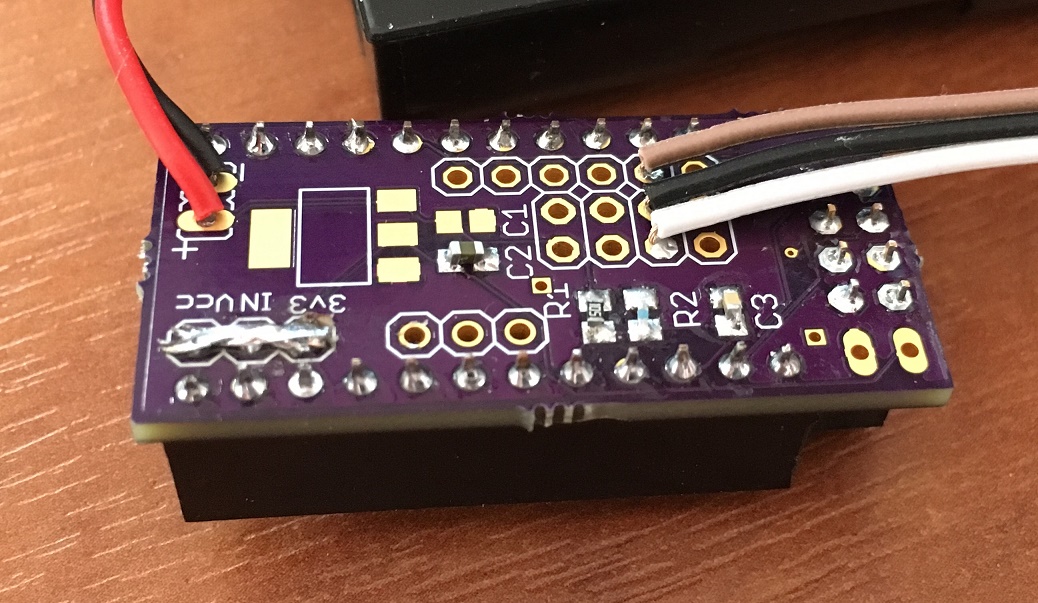
Is there a mysensor thread for this "mysensor" pro mini adapter?@NeverDie Thanks i'd took the 1 led off but have taken d13 and the regulator off now. Sitting at around 2.7v although as i'm more so testing i'm reporting the temp as often as every 5mins if it changes.
-
Universal board bought from from Slovenia Radio Woes. (solved)@kenci Hi Kenci, yeah i'd been in contact with him through ebay as i purchased it from him but sadly he wasn't able to assist too much as he said he was a hardware rather than software guy. I figured it out in the end, wasn't rocket science and just took a little digging which i'm not adverse too but just couldn't see it at first.
-
Is there a mysensor thread for this "mysensor" pro mini adapter?If anyone is thinking of using this board Cory produced a PDF which has build instructions for 3.3 and 5v, I've uploaded it so it's easy for people to find.
-
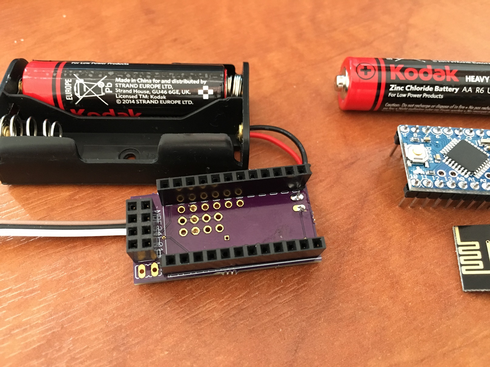
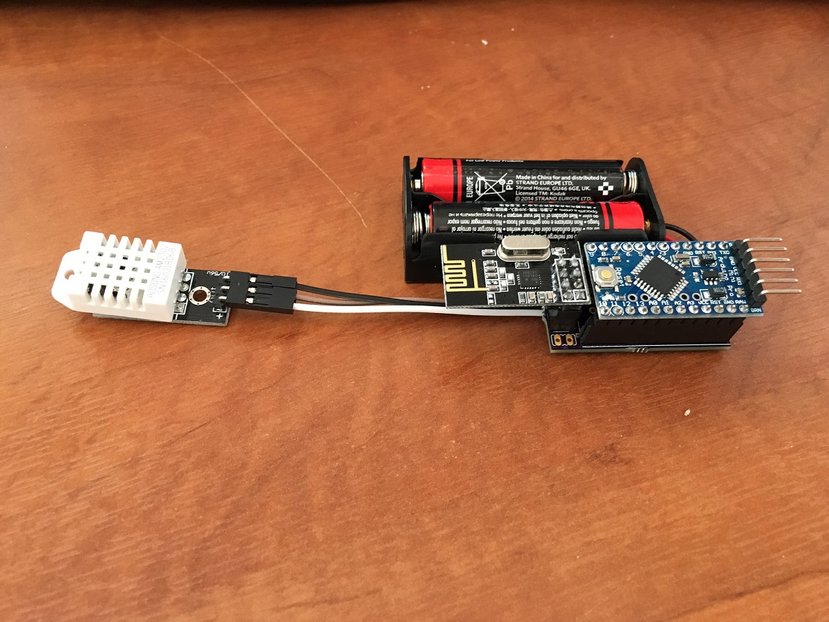
Is there a mysensor thread for this "mysensor" pro mini adapter?In case anyone is interested this is what the assembled board looks like on mine minus any case. You could get it a lot thinner if you skipped the connectors and soldered directly but i've an aversion to that as i keep tinkering.
-
Universal board bought from from Slovenia Radio Woes. (solved)@mfalkvidd @MikeF I've now resolved the issue. With this board you have to set D3 high so that it powers the radio, shame as that really ties pin 3 up then but i guess he's done it to make the radio optional as he supports bluetooth as well. It's a nice lower power board but i think i've been spoilt by the otherboards i've used which have used the same pinouts etc. I think the solar one which you have may have been of more use thinking about it but hey ho. It's trivial but just incase anyone else is as simple minded as me i put the following in setup
pinMode(3, OUTPUT);
digitalWrite(3,HIGH);Thanks
Col -
Universal board bought from from Slovenia Radio Woes. (solved)@MikeF Hi Mike, thanks for the response. Yeah i'm on 1.5. I've just removed the libraries just incase and reinstalled and uploaded the serial gateway as well as the sensor itself for completeness. Still getting radio init fail
-
Universal board bought from from Slovenia Radio Woes. (solved)Hi Guys,
Has anyone bought one of these boards? I've modified my code so that it works with pin 7 and 8 as he's these rather than the regular radio attachment pins. I'm just getting Radio Init Failed messages, any advice?MyTransportNRF24 transport(7, 8); // Ceech board, 3.3v (7,8) MySensor gw(transport);I've tried external power as well as battery power with the same results.
-
Is there a mysensor thread for this "mysensor" pro mini adapter?What size SMD did you use for yours? I might see if i can get a variety pack myself from amazon, i'm in the uk so have access to amazon. I think one of the resistors is 470r rather than 470k so the voltage divider didn't work although as i'm feeding it with 3v from two AA i used the internal reference method which worked well. I have to say i thought it ended up being quite long too and then when paired with the sensors you end up with some funny shapes to try and fit in a box :-)
Col
-
Is there a mysensor thread for this "mysensor" pro mini adapter?I've just actually got around to soldering mine together today after having the pcb's sitting there for months. I had ordered a load of capacitors and resistors but rather naively didn't realise that there were different sizes for smd components, silly looking back now but just didn't realise. My soldering skills have improved slightly though so had another go and managed to assemble it today. Biggest problem was remembering what smd components were which as the ebay sellers never label them well.
Have you ordered some already?
Col
-
PIR won't revert to not activated.@TheoL I tested everything again tonight and did some troubleshooting using the default motion sketch which worked. What i ascertained is that my sketch was setting the motion sensor active but then never sending a signal to say that the sensor was no longer active. I'll be honest that i couldn't see the default sketch doing this either(unless it does this via an interrupt when it goes from active to inactive) but i modified my program so that it now sends a notification that the sensor is no longer tripped which solved that issue. I also put a 10 second delay in as the lowest setting i could set on the sensor was 5 seconds or so which meant my sketch spammed domoticz that it was tripped. With the delay it sends a message to domoticz once now, waits 10 seconds and then sends that it's no longer tripped. With this I've been able to enable the domoticz control so that it will turn the relevant light on for 1 min at %75 if motion is detected.
The only issue i've ran into is if i've already got the light set to say %20 which i like to do after sunset then when the light gets enabled for 1 min domoticz doesn't seen to turn it off.
