Skip to content
  • MySensors
  • OpenHardware.io
  • Categories
  • Recent
  • Tags
  • Popular
Skins
  • Light
  • Brite
  • Cerulean
  • Cosmo
  • Flatly
  • Journal
  • Litera
  • Lumen
  • Lux
  • Materia
  • Minty
  • Morph
  • Pulse
  • Sandstone
  • Simplex
  • Sketchy
  • Spacelab
  • United
  • Yeti
  • Zephyr
  • Dark
  • Cyborg
  • Darkly
  • Quartz
  • Slate
  • Solar
  • Superhero
  • Vapor

  • Default (No Skin)
  • No Skin
Collapse
Brand Logo
F

f1dev

@f1dev
About
Posts
8
Topics
1
Shares
0
Groups
0
Followers
0
Following
0

Posts

Recent Best Controversial

  • !TSM:FPAR:FAIL, standalone 328p + Nrf24L01+
    F f1dev

    So, after pulling my (now grey) hair, end after trying different sketches, both stable and beta version (2.0.1) of mysensors, different boot loaders, different fuses and so on, I discovered that if I connect the radio via cables and not directly to the board everything works as expected. Tried different radios and different boards with the same result.
    There are 2 caps near the radio, 10uF and 100nF.

    I´m not that skilled in electronics, so how come? Anybody knows? Is the radio to close to the mcu?

    Attached is a picture showing my boards.
    0_1474884471664_IMG_4773.JPG.jpeg

    Troubleshooting

  • !TSM:FPAR:FAIL, standalone 328p + Nrf24L01+
    F f1dev

    Hi all!
    First, thanks all for this great project! So fun tinkering with electronics and programming!
    I have been running about 10 nodes for almost 2 years now, they are based on Pro Mini boards and running great in a mixed environment with versions from 1.4 to 2.0.

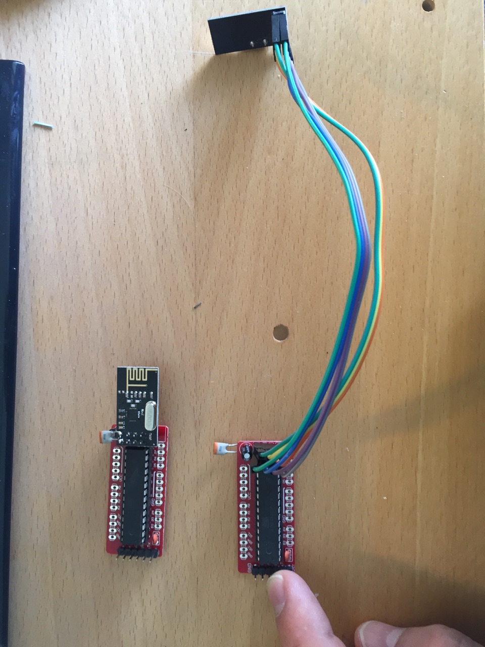
    Now I would like to do my own nodes from scratch, based on a bare Atmega328p-pu instead running at 3.3V, 8Mhz internal clock powered by 2xAA inspired by the "My Slim 2xAA Node" here on the forum.

    This is what I have done:

    I have changed fuses so I can run them on 3.3V @8Mhz internal clock with no BOD. (LFUSE: 0xE2 ,HFUSE: 0xDA ,EFUSE 0x07 (or 0xFF). And I have wrote a new bootloader as described here - Minimal setup, https://www.arduino.cc/en/Tutorial/ArduinoToBreadboard

    It seems its running ok standalone with 3.3 power supply and without any crystal, and I can upload mysensors sketches via serial interface and so on. The radio is connected, and an extra 10uF capacitor is connected on the radio.

    But now the trouble begins..
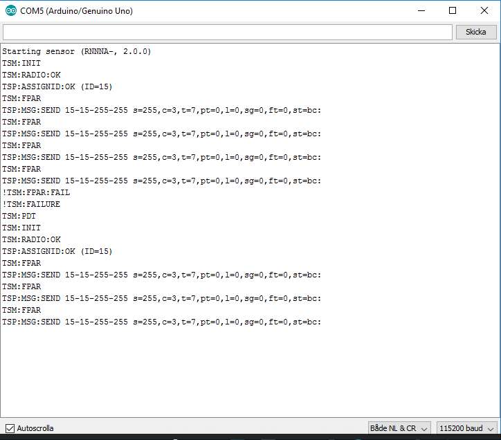
    When it starts up it inits the radio and try to connect but it doesn't seem to speak with the gateway as I get the following error when debugging:
    0_1474633292986_Skärmklipp_standalone.PNG

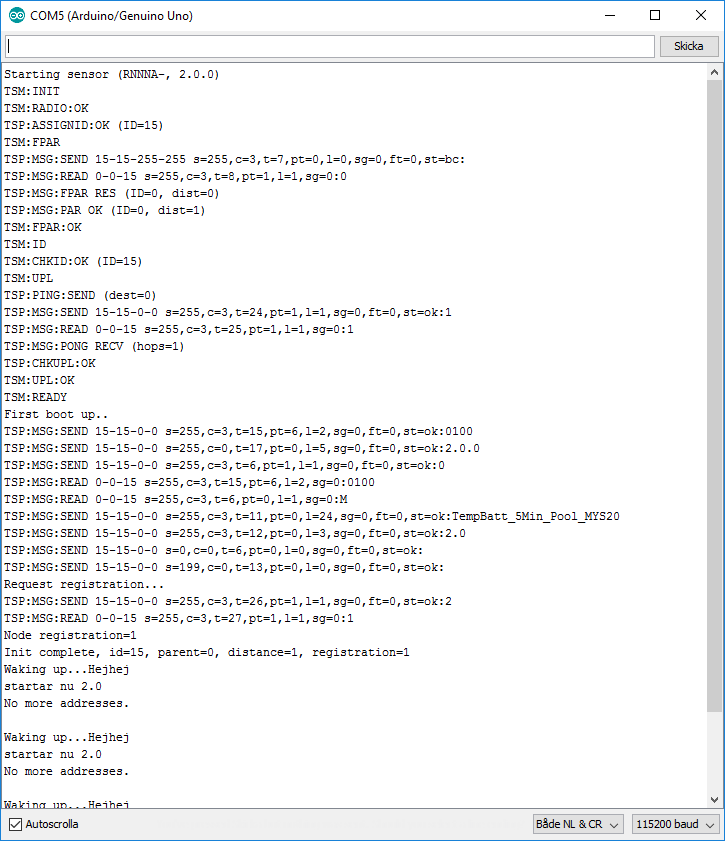
    If I put the processor in at spare UNO and moves the radio to that board it starts up ok and can connect to the gateway,
    0_1474633305073_Skärmklipp_uno.PNG
    I have connected a 16Mhz crystal to the standalone circuit but that does not make any difference.
    I hav powered the breadboard mcu with 3.3V from my UNO and batteries (2xAA) but that doesn't make any difference either.

    I have no ideas what I should test next, any ideas?
    Environment: Win 10, Arduino IDE 1.6.11, Mysensors 2.0

    Troubleshooting

  • Windows GUI/Controller for MySensors
    F f1dev

    Very interesting, I´m having the exact issues with my pro minis.. It would be very helpful with a " how-to" to compile the Mysbootloader for pro minis 3.3V 8mhz.

    Kindly

    Controllers myscontroller mysbootloader

  • Mailbox/Postbox Alert
    F f1dev

    @n3ro - Thanks, that was really helpfull!:smile:

    My Project

  • Mailbox/Postbox Alert
    F f1dev

    Nope, havent done that yet. It´s a "stock" 3v3 pro mini. Still reading up on how to do that and how to change to MYS-bootloader, curious on how OTA-update works.
    Big thanks for your respons! :smile:

    My Project

  • Mailbox/Postbox Alert
    F f1dev

    @n3ro Ok, thanks! Then I learned something new today.. IRQ is only needed for receiving nodes then, like repeaters and gateways, right?
    Strange though that my circuit draws so much more current than yours. I have tested different setups, different arduinos and different radios from different suppliers with same result.
    Well, at least my mailbox are mysensored now! :smiley:

    My Project

  • Mailbox/Postbox Alert
    F f1dev

    Ok, so I found that it is the radio that draws about 7mA when I ground input pin 2, it is connected to IRQ-pin on the radio.
    @n3ro Have you connected the radio as described on the build-page? [http://www.mysensors.org/build/connect_radio](link url)

    My Project

  • Mailbox/Postbox Alert
    F f1dev

    Hi!
    I+m trying to do a similar mailbox sensor, but I get different power consumptions hen I ground (pulling down) input pin 2 and 3.

    I´m using a pro mini, 3.3v standard boot loader with removed LED and 470k resistors as external pull-ups.

    In sleep mode with it draws about 65uA
    Roughly the same with input pin 3 -grounded (state 0)
    But when I ground pin 2 it draws 7mA

    Any ideas whats wrong?

    My Project
  • Login

  • Don't have an account? Register

  • Login or register to search.
  • First post
    Last post
0
  • MySensors
  • OpenHardware.io
  • Categories
  • Recent
  • Tags
  • Popular