Skip to content
  • MySensors
  • OpenHardware.io
  • Categories
  • Recent
  • Tags
  • Popular
Skins
  • Light
  • Brite
  • Cerulean
  • Cosmo
  • Flatly
  • Journal
  • Litera
  • Lumen
  • Lux
  • Materia
  • Minty
  • Morph
  • Pulse
  • Sandstone
  • Simplex
  • Sketchy
  • Spacelab
  • United
  • Yeti
  • Zephyr
  • Dark
  • Cyborg
  • Darkly
  • Quartz
  • Slate
  • Solar
  • Superhero
  • Vapor

  • Default (No Skin)
  • No Skin
Collapse
Brand Logo
LukasppL

Lukaspp

@Lukaspp
About
Posts
6
Topics
1
Shares
0
Groups
0
Followers
0
Following
0

Posts

Recent Best Controversial

  • 💬 RFM69 Livolo 2 channels 1 way EU switch(VL-C700X-1_Ver_C2)
    LukasppL Lukaspp

    @Lukaspp said in 💬 Livolo 2 channels 1 way EU switch(VL-C700X-1_Ver_C2):

    @Lukaspp : The Above pdf was tested with a simulation program but when I tested using real components I can not get the theoretical results. I had to ajust allmost to the original circuit from Shabba and the best power was 2.4V/13 ma. It is not enought for the couple Atmega328-8Mhz + NFR24l01. So, if the project friends want it is going further, the power Supply has to be out of this board. the rest of the board could be used. Opto Transistors TR1/TR2/ and Triacs. This is the final pdf for 2.4V/13ma.

    0_1505789467439_SwPowerSupplyTested.pdf

    OpenHardware.io mysensors livolo

  • 💬 RFM69 Livolo 2 channels 1 way EU switch(VL-C700X-1_Ver_C2)
    LukasppL Lukaspp

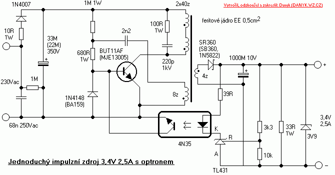
    @shabba A. Power Supply.
    This is the standard circuit for a the power supply.

    0_1505765000438_upload-731c55be-0c76-4d93-9329-931a1f8aaf4d

    I redrawn your circuit trying to use the standard form and I can observe it can not provide enough current for both (Atmega328+ nFR24l01)**. So, I adjusted some components for getting 3.3V and 22ma. Atmega328-8Mhz + nFR24l01 Without LEd´s ~ 18ma/3V

    **It is Worst for RFM69 which has more consume.

    0_1505767324846_SwPowerSupply4.pdf

    OpenHardware.io mysensors livolo

  • 💬 RFM69 Livolo 2 channels 1 way EU switch(VL-C700X-1_Ver_C2)
    LukasppL Lukaspp

    Shabba,
    I can see, you was working three months ago in this project and you have some initial circuit draft. I know about this kind of devices and I can help you if you are still working on it.
    We can split the circuit as following:
    a. Power supply: TRANS1(You are right, it is high frequency transformer), high voltage transistor MJE13001 (Q1), optocoupler (U7) and some additional components.
    b. Optocouplers interface: for signals from the control board: TR1/U2/BRG6, TR2/U3/BRG3 and some additional components.
    c. Triacs (Power Circuits) : T1, T2.
    Please let me know for working together.

    Thanks and best regards

    OpenHardware.io mysensors livolo

  • How can I get Arduino working even it can not connect with Gate Way?
    LukasppL Lukaspp

    Dear friend,

    Thanks Nca78. I will wait or the new release.

    Best regards

    My Project

  • How can I get Arduino working even it can not connect with Gate Way?
    LukasppL Lukaspp

    I would like to have Arduino working and making its local job (example : dimming lights and the local buttons) even the Gate Way (GW) is out of service.

    How can I get Arduino going to the Loop routine after a three attempts to get the GW and does not get it connected (because GW is out of order)?

    Right now if the GW did not answered the Arduino will try to connect the GW over and over, making reset every 4 tries.

    I am using the last release for Arduino Pro mini and NRF24L01.

    Thanks for myour help and best regards

    My Project
  • Login

  • Don't have an account? Register

  • Login or register to search.
  • First post
    Last post
0
  • MySensors
  • OpenHardware.io
  • Categories
  • Recent
  • Tags
  • Popular