Navigation

    • Register
    • Login
    • OpenHardware.io
    • Categories
    • Recent
    • Tags
    • Popular
    1. Home
    2. mckenzi
    3. Posts
    • Profile
    • Following
    • Followers
    • Topics
    • Posts
    • Best
    • Groups

    Posts made by mckenzi

    • RE: How to connect QUIP300 to Domoticz

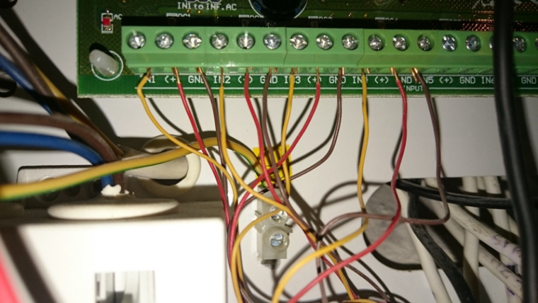
      Relay is working correctly, checked with multimeter. Now i'm study about debugging.
      Below is the code i'm using (4 PIRs).
      Problem with sleep mode?

      
      // Enable debug prints
      // #define MY_DEBUG
      
      // Enable and select radio type attached
      #define MY_RADIO_NRF24
      //#define MY_RADIO_RFM69
      
      #include <MySensors.h>
      #define MY_NODE_ID AUTO
      unsigned long SLEEP_TIME = 5000 ; // 120000 Sleep time between reports (in milliseconds)
      #define DIGITAL_INPUT_SENSOR1 2   // The digital input you attached your motion sensor.  (Only 2 and 3 generates interrupt!)
      #define DIGITAL_INPUT_SENSOR2 3   // The digital input you attached your motion sensor.  (Only 2 and 3 generates interrupt!)
      #define DIGITAL_INPUT_SENSOR3 4   // The digital input you attached your motion sensor.  (Only 2 and 3 generates interrupt!)
      #define DIGITAL_INPUT_SENSOR4 5   // The digital input you attached your motion sensor.  (Only 2 and 3 generates interrupt!)
      
      #define CHILD_ID_PIR1 21   // Id of the sensor child
      #define CHILD_ID_PIR2 22   // Id of the sensor child
      #define CHILD_ID_PIR3 23   // Id of the sensor child
      #define CHILD_ID_PIR4 24   // Id of the sensor child
      
      // Enable repeater functionality for this node
      #define MY_REPEATER_FEATURE
      
      // Initialize motion message
      MyMessage msg1(CHILD_ID_PIR1, V_TRIPPED);
      MyMessage msg2(CHILD_ID_PIR2, V_TRIPPED);
      MyMessage msg3(CHILD_ID_PIR3, V_TRIPPED);
      MyMessage msg4(CHILD_ID_PIR4, V_TRIPPED);
      
      void setup()
      {
        pinMode(DIGITAL_INPUT_SENSOR1, INPUT);      // sets the motion sensor digital pin as input
        pinMode(DIGITAL_INPUT_SENSOR2, INPUT);      // sets the motion sensor digital pin as input
        pinMode(DIGITAL_INPUT_SENSOR3, INPUT);      // sets the motion sensor digital pin as input
        pinMode(DIGITAL_INPUT_SENSOR4, INPUT);      // sets the motion sensor digital pin as input
       }
      
      void presentation()
      {
        // Send the sketch version information to the gateway and Controller
        sendSketchInfo("PIR Sensor", "0.1");
      
        // Register all sensors to gw (they will be created as child devices)
        present(CHILD_ID_PIR1, S_MOTION);
        present(CHILD_ID_PIR2, S_MOTION);
        present(CHILD_ID_PIR3, S_MOTION);
        present(CHILD_ID_PIR4, S_MOTION);
      }
      
      void loop()
      {
      // Read digital motion value (PIR1)
        bool tripped1 = digitalRead(DIGITAL_INPUT_SENSOR1) == HIGH;
        if(digitalRead(DIGITAL_INPUT_SENSOR1) == HIGH)
          tripped1 = true;
         else 
          tripped1 = false;
      // Read digital motion value (PIR2)
        bool tripped2 = digitalRead(DIGITAL_INPUT_SENSOR2) == HIGH;
        if(digitalRead(DIGITAL_INPUT_SENSOR2) == HIGH)
          tripped2 = true;
         else 
          tripped2 = false;
      // Read digital motion value (PIR3)
         bool tripped3 = digitalRead(DIGITAL_INPUT_SENSOR3) == HIGH;    
         if(digitalRead(DIGITAL_INPUT_SENSOR3) == HIGH)
          tripped3 = true;
         else 
          tripped3 = false;
      // Read digital motion value (PIR4)
        bool tripped4 = digitalRead(DIGITAL_INPUT_SENSOR4) == HIGH;
        if(digitalRead(DIGITAL_INPUT_SENSOR4) == HIGH)
          tripped4 = true;
         else 
          tripped4 = false;


        Serial.println(tripped1);
        send(msg1.set(tripped1?"1":"0"));  // Send tripped value to gw
        
        Serial.println(tripped2);
        send(msg2.set(tripped2?"1":"0"));  // Send tripped value to gw
      
        Serial.println(tripped3);
        send(msg3.set(tripped3?"1":"0"));  // Send tripped value to gw
        
        Serial.println(tripped4);
        send(msg4.set(tripped4?"1":"0"));  // Send tripped value to gw
        
      // Sleep until interrupt comes in on motion sensor. Send update every two minute.
        sleep(digitalPinToInterrupt(DIGITAL_INPUT_SENSOR1), CHANGE, SLEEP_TIME);
          sleep(digitalPinToInterrupt(DIGITAL_INPUT_SENSOR2), CHANGE, SLEEP_TIME);
            sleep(digitalPinToInterrupt(DIGITAL_INPUT_SENSOR3), CHANGE, SLEEP_TIME);
              sleep(digitalPinToInterrupt(DIGITAL_INPUT_SENSOR4), CHANGE, SLEEP_TIME);
      
      
      }
      
      posted in Hardware
      mckenzi
      mckenzi
    • RE: How to connect QUIP300 to Domoticz

      If my understanding is correct it works as follows:
      (HIGH : when relay is closed, connected to digital pin & 5V VCC)
      1- HIGH->TRUE-> msg.set 1
      2- LOW->FALSE->msg.set 0

      It works but it's very unstable. Sometimes working sometimes not.
      Is it necessary to add some resistors to this circuit?

      posted in Hardware
      mckenzi
      mckenzi
    • RE: How to connect QUIP300 to Domoticz

      Hi Gohan,

      This is the way i should follow ?:

      	// Read digital motion value
      	
        if(digitalRead(DIGITAL_INPUT_SENSOR) == HIGH){
          tripped = true;
        } else {
          tripped = false;
        }
      

      Not so easy to set 🙂

      posted in Hardware
      mckenzi
      mckenzi
    • RE: How to connect QUIP300 to Domoticz

      Hi GOHAN,

      Finally i've build my serial gateway ( Arduino UNO + nRF24) + node (Arduino Nano + nRF24) but i failed with PIR conection to my NODE. How should i connect PIR's relay to Nano ? ( digital input + GND ) ?
      Now i know that relay is normally closed ( 0, 1 state, no power on it)
      I was trying to connect this way and it was working for few second ( i saw in the serial monitor , 1 , 0) but after some time NODE was sending weird data to GW.
      How connect it corectlly and how to mod the sketch for more sensors? (4 pcs). ```
      This is the way ?

      #define DIGITAL_INPUT_SENSOR 3   // The digital input you attached your motion sensor.  (Only 2 and 3 generates interrupt!)
      #define CHILD_ID 1   // Id of the sensor child
      #define DIGITAL_INPUT_SENSOR 4   // The digital input you attached your motion sensor.  (Only 2 and 3 generates interrupt!)
      #define CHILD_ID 2   // Id of the sensor child```
      posted in Hardware
      mckenzi
      mckenzi
    • RE: How to connect QUIP300 to Domoticz

      THank you Gohan. Now everything is more clearer. 🙂 Will try today to wire everything.

      posted in Hardware
      mckenzi
      mckenzi
    • RE: How to connect QUIP300 to Domoticz

      Last question: one pin of each PIR's relay must be connected to common Arduino GND pin, right ?

      posted in Hardware
      mckenzi
      mckenzi
    • RE: How to connect QUIP300 to Domoticz

      So how to connect 4 PIRs to one node to be able to see in Domoticz which was acivated ?

      posted in Hardware
      mckenzi
      mckenzi
    • RE: How to connect QUIP300 to Domoticz

      Yellow cable is connected to PIR's relay. And this cable i'm going to conect to digital input of arduino.
      Second cable from PIR's relay will be connnected to arduino's GND pin. ( not shown on this photo).
      There is no voltage on PIR's relay ( works as simple switch).
      Is my understanding correct ?

      posted in Hardware
      mckenzi
      mckenzi
    • RE: How to connect QUIP300 to Domoticz

      Hi, panel will be use as a power supply only.

      posted in Hardware
      mckenzi
      mckenzi
    • RE: How to connect QUIP300 to Domoticz

      Hi Gohan, please see my set up i more details.
      Each of PIR is conected to old/not used alarm control panel.
      Now it is used as power supply. I've just ordered Arduino Nano + nRF24L01 to conect all motion sensors. I would like to use one of free port to power my node (thru voltage step down : 12V->5V)
      0_1497296131460_sensors.JPG
      How should i conect sensors to node?

      posted in Hardware
      mckenzi
      mckenzi
    • RE: How to connect QUIP300 to Domoticz

      I can swich to MySensors- no problem.

      posted in Hardware
      mckenzi
      mckenzi
    • RE: How to connect QUIP300 to Domoticz

      Yes. Possible?

      posted in Hardware
      mckenzi
      mckenzi
    • RE: How to connect QUIP300 to Domoticz

      Hey gohan, thanks - basic sketch will do the job.
      I faced another problem. Now i've conected one of the PIR via WemosD1 mini with ESP Easy.0_1497208049084_DSC_0864.JPG
      And works very well.
      But i would like to connect 3 more sensors.
      Power supply for PIR and Wemos is different and there is only one GND pin .
      Any idea how to make it?

      posted in Hardware
      mckenzi
      mckenzi
    • RE: How to connect QUIP300 to Domoticz

      Hello Gohan ,

      Here is my sketch. Arduino is conected via uSB cable to my QNAP.
      And there is few relays conected to Arduino. I would like to avoid wireless conection.

      Now i would like to add PIRs to this sketch.


      // Enable debug prints to serial monitor
      #define MY_DEBUG 
      
      
      // Enable and select radio type attached
      //#define MY_RADIO_NRF24
      //#define MY_RADIO_RFM69
      
      // Set LOW transmit power level as default, if you have an amplified NRF-module and
      // power your radio separately with a good regulator you can turn up PA level. 
      //#define MY_RF24_PA_LEVEL RF24_PA_LOW
      
      // Enable serial gateway
      #define MY_GATEWAY_SERIAL
      
      // Define a lower baud rate for Arduino's running on 8 MHz (Arduino Pro Mini 3.3V & SenseBender)
      #if F_CPU == 8000000L
      #define MY_BAUD_RATE 38400
      #endif
      
      // Flash leds on rx/tx/err
      // #define MY_LEDS_BLINKING_FEATURE
      // Set blinking period
      // #define MY_DEFAULT_LED_BLINK_PERIOD 300
      
      // Inverses the behavior of leds
      // #define MY_WITH_LEDS_BLINKING_INVERSE
      
      // Enable inclusion mode
      #define MY_INCLUSION_MODE_FEATURE
      // Enable Inclusion mode button on gateway
      #define MY_INCLUSION_BUTTON_FEATURE
      
      // Inverses behavior of inclusion button (if using external pullup)
      //#define MY_INCLUSION_BUTTON_EXTERNAL_PULLUP
      
      // Set inclusion mode duration (in seconds)
      #define MY_INCLUSION_MODE_DURATION 60 
      // Digital pin used for inclusion mode button
      #define MY_INCLUSION_MODE_BUTTON_PIN  3 
      
      // Uncomment to override default HW configurations
      //#define MY_DEFAULT_ERR_LED_PIN 4  // Error led pin
      //#define MY_DEFAULT_RX_LED_PIN  6  // Receive led pin
      //#define MY_DEFAULT_TX_LED_PIN  5  // the PCB, on board LED
      
      #include <SPI.h>
      #include <MySensors.h>  
      #include <Bounce2.h>
      
      // Enable repeater functionality for this node
      #define MY_REPEATER_FEATURE
      
      
      #define RELAY_1  4  // Arduino Digital I/O pin number for first relay (second on pin+1 etc)
      #define NUMBER_OF_RELAYS 1 // Total number of attached relays
      #define RELAY_ON 1  // GPIO value to write to turn on attached relay
      #define RELAY_OFF 0 // GPIO value to write to turn off attached relay
      
      #define BUTTON_PIN A1
      
      
      void before() { 
        for (int sensor=1, pin=RELAY_1; sensor<=NUMBER_OF_RELAYS;sensor++, pin++) {
          // Then set relay pins in output mode
          pinMode(pin, OUTPUT);   
          // Set relay to last known state (using eeprom storage) 
          digitalWrite(pin, loadState(sensor)?RELAY_ON:RELAY_OFF);
        }
      }
      Bounce debouncer = Bounce();
      
      void setup() { 
        // Setup locally attached sensors
        delay(10000);
         // Setup the button.
        pinMode(BUTTON_PIN, INPUT_PULLUP);
        // After setting up the button, setup debouncer.
        debouncer.attach(BUTTON_PIN);
        debouncer.interval(5);
        //presentation();
      }
      void presentation()  
      {   
        // Send the sketch version information to the gateway and Controller
        sendSketchInfo("Relay", "1.0");
      
        for (int sensor=1, pin=RELAY_1; sensor<=NUMBER_OF_RELAYS;sensor++, pin++) {
          // Register all sensors to gw (they will be created as child devices)
          present(sensor, S_LIGHT);
        }
      }
      
      MyMessage msg(1, V_LIGHT);
      
      void loop() { 
        // Send locally attached sensor data here 
        if (debouncer.update()) {
          // Get the update value.
          int value = debouncer.read();
          // Send in the new value.
          if(value == LOW){
               saveState(1, !loadState(1));
               digitalWrite(RELAY_1, loadState(1)?RELAY_ON:RELAY_OFF);
               send(msg.set(loadState(1)));
          }
        }
      }
      
      
      void receive(const MyMessage &message) {
        // We only expect one type of message from controller. But we better check anyway.
        if (message.type==V_LIGHT) {
           // Change relay state
           digitalWrite(message.sensor-1+RELAY_1, message.getBool()?RELAY_ON:RELAY_OFF);
           // Store state in eeprom
           saveState(message.sensor, message.getBool());
           // Write some debug info
           Serial.print("Incoming change for sensor:");
           Serial.print(message.sensor);
           Serial.print(", New status: ");
           Serial.println(message.getBool());
         } 
      }


      How to make it ? I'm newbie - sorry.

      Regards.

      posted in Hardware
      mckenzi
      mckenzi
    • RE: How to connect QUIP300 to Domoticz

      Thank you Nca78 & gohan.
      Sensor is working very well conected to Wemos D1 mini under Domoticz control. Not i'm testing with 9V battery .
      I faced some problems with conection to Arduino . Basic sketch for motion sensor not working for my setup.
      Any clues how to modify my current sketch ? (for relays)
      0_1497042712762_GatewaySerialWired.ino

      Thank you.

      posted in Hardware
      mckenzi
      mckenzi
    • How to connect QUIP300 to Domoticz

      Dear all,

      I would like to ask for your kind support with this PIR. Currently i'm using Arduino UNO (few relays ) as a gateway to Domoticz system installed on my QNAP ( connected via USB cable) . Everything works perfect.

      Now i found that i have old security system which is unused. And there are 4 PIR as on the attached photo.
      alt text
      Is the any chance to conect to my controler(DOMOTICZ) ?
      (ESP8266 Arduino Uno, Raspberry PiOW) ?
      Thanks in advance for any suggestion!

      Best regards.

      posted in Hardware
      mckenzi
      mckenzi