Navigation

    • Register
    • Login
    • Search
    • OpenHardware.io
    • Categories
    • Recent
    • Tags
    • Popular
    1. Home
    2. Myna
    3. Posts
    • Continue chat with Myna
    • Start new chat with Myna
    • Flag Profile
    • Profile
    • Following
    • Followers
    • Blocks
    • Topics
    • Posts
    • Best
    • Groups

    Posts made by Myna

    • RE: 2AA Sensor Board + RPI Gateway + RGBW Dimmer

      Testing the folowing hardware:

      12421748_10208518385382383_125320644_n.jpg

      12395298_10208518385462385_856753459_n.jpg

      It seems to work (basic hardware test). It still miss the DC/DC convefter and PIR sensor.

      However, I have a very strange problem with RFM69:

      gateway -> node rfm communication seems to have a very good range (Even with no antenna on the gateway, work everywhere in my appartment). But node -> gateway dont work past 30 ou 40cm. Tested with same 3.3V regulated supply. Any idea?

      Thanks!

      posted in My Project
      Myna
    • RE: 2AA Sensor Board + RPI Gateway + RGBW Dimmer

      @DavidZH Of course, this is an openharware project, everything will be released ! I can share the files in the current state but this is early dev state: I've already found two errors in the PCBs.

      After some soldering and fiddling with software I have the gateway talking to one sensorboard : I'm excited !

      posted in My Project
      Myna
    • RE: 2AA Sensor Board + RPI Gateway + RGBW Dimmer

      PCB and some components are are now arrived ! PCB are from Elecrow, I'm pretty satisfied with the result and silkscreen.

      Hopefully I will be able to start some tests this weekend.

      **2AA Multisensorboard: **
      IMG_20151218_175039.jpg

      **RGBW Dimmer board: **
      IMG_20151218_174637.jpg

      **Raspberry Pi Serial Node : (fit in this little plastic case) **
      IMG_20151218_173920.jpg

      Myna

      posted in My Project
      Myna
    • RE: 2AA Sensor Board + RPI Gateway + RGBW Dimmer

      Hi there !

      I'm waiting for the boards and some components. Then I will be able to test, and write drivers (E931.96, no driver at the moment) and software for the system.

      I'm cleaning my files / schematics to release everything.

      I wasn't really aware of MYSX connector. After looking the PDF specs, It's not even clear how many pins it has, it look like every new versions add some pins ? It could be considered for a future version.

      The thing is I have never worked on an home automation before, nor mysensors. So the idea here was to design a few board that are enough for my basic project needs (RGBW lighting, low voltage halogen lighting, multiple multisensor, Jeedom RPI controller). At the moment I don't really know what flavor of extensions I would one day like to add to the boards so I tried to breakout a maximum of pins, with clear silkscreen, even if it makes the boards bigger. I see this as a dev project to dive into mysensors. Future rev will probably follow if it works for me.

      Myna

      posted in My Project
      Myna
    • RE: 2AA Sensor Board + RPI Gateway + RGBW Dimmer

      Thanks guys ! I think it will be itead studio as it seems they have the cheaper price for 5*10cm. I've checked the board with Seeed DRU.

      The last board : an RGBW and DC PWM dimmer. I'm really into lighting design, so that's very important for me.

      **Specs: **

      • 5 to 24V input. Work with 5, 12 or 24V led strip or power LEDs.
      • should handle 3-4A per output with no problem. AO4496 Mosfets. (depend of PWM frequency)
      • measure of the LEDs supply voltage ( resistor bridge to ADC)
      • measure of the LEDs supply current (sense resistor, INA138 to ADC)
      • DATA and GND header to drive intelligent LED strips (WS2812 , etc)
      • Power and LEDs / LED Strip connection trough 3.5mm screw headers
      • OTA hardware (spi flash), RGBW 5050 monitor LED, expansion ports as usual

      mynaLEDV1.jpg

      Now let's final check the board and make the order !

      posted in My Project
      Myna
    • RE: Step-by-step procedure to connect the NRF24L01+ to the GPIO pins and use the Raspberry as a Serial Gateway (MySensors 1.x)

      This is a very good work !

      Is there anything in place for RFM69 ? Would it be difficult to port the code from arduino to rpi ? (I have never coded on RPI).

      Also, do you think any performance difference is involved in managing the radio directly from the RPI, compared to having a dedicated atmega/arduino ? Especially if a controller solution is already running on it?

      posted in Hardware
      Myna
    • RE: 2AA Sensor Board + RPI Gateway + RGBW Dimmer

      Hi ! A new board today :

      I don't have any gateway or controller at the moment, and I plan to use Jeedom on a Raspberry Pi 2. So I've routed a little serial gateway for RPI. The board use the native serial port of the RPI (tough it should be more stable than going trough an usb/serial chip ? ). Also, I added a 3.3V LDO so that the gateway don't use the RPI 3.3V and a RGBW for monitoring / debug purposes.

      mynagateV1.jpg

      The idea is to fit this and the raspberry in a normal enclosure. It should just need a hole for the SMA connector :

      rpigate.jpg

      Any advice for RPI cases ?

      Myna

      posted in My Project
      Myna
    • RE: 2AA Sensor Board + RPI Gateway + RGBW Dimmer

      IMG_20151120_180219.jpg

      posted in My Project
      Myna
    • RE: 2AA Sensor Board + RPI Gateway + RGBW Dimmer

      Thanks Gert ! It's Eagle 7.3.0 light. Maybe not the best but the one I know... (I have the idea of switching to Altium)

      posted in My Project
      Myna
    • RE: 2AA Sensor Board + RPI Gateway + RGBW Dimmer

      Hi !

      Some news:

      I've finished the drawing of V1.0. The main change is the following: Pressure sensor and IMU removed. The idea of this board is to be the universal sensor, and make it multiple time. I couldn't really find an use for these sensors. If I need them, it will be on one board, and so a little extension board is OK. Also, it save a bit of space for cleaner routing.

      So it will be Movement/Light/Temp/Humidity/RGBW LEDs/ (Extensions)

      The board size is 35*60mm, the idea is to solder this model of battery holder under it: 42767313.jpg

      I've started to order some of the components. I didn't ordered PCBs since 2013, is Seeed/Itead still the way to go for cheap good PCBs ?

      The board:

      mynaV1.jpg

      Silkscreen is in yellow. Is it OK to use the logo of MySensors as I did ? I prefer to be sure...

      Myna

      posted in My Project
      Myna
    • RE: 2AA Sensor Board + RPI Gateway + RGBW Dimmer

      @scalz said:

      cool.
      just for curiosity, did you calculated all res tied to gnd, like dividers, sort of low power killers? Is it your bus current data?

      Not yet. I'll use the biggest possible values to loose as few as possible power in theses...

      I'm thinking of wiring the supply of the flash memory chip on the CS. So, the chip will only be powered when selected on the spi bus. Easy mod, because the CS is already there (not the same with I2C...)

      posted in My Project
      Myna
    • RE: 2AA Sensor Board + RPI Gateway + RGBW Dimmer

      I made a crude sheet to estimate the price and batt life impact of each part.

      Clearly, the MPU is the worst part. But I don't expect to use this sensor often. But even with these numbers, the full board would last 7 years in sleep mode.

      tab1.png

      posted in My Project
      Myna
    • RE: 2AA Sensor Board + RPI Gateway + RGBW Dimmer

      @Yveaux said:

      @Myna said:

      Use an MCP16252 to generate 3.3V that is enabled by default but can be switched off (and so bypassed) by the MCU if the batteries voltage is enough.

      I like the idea, but how is the MCU powered when it switches off the batteries?
      Seems to me that +3V3 will not receive any juice then.

      Hi, the MCP16252 is special : when disabled, it connects the output to the input with an internal P mosfet. The MCP16251 is the same regulator with output disconnect when disabled.

      posted in My Project
      Myna
    • RE: 2AA Sensor Board + RPI Gateway + RGBW Dimmer

      The PIR sensor if probably the part that gives me the more difficulties and I'm still unsure. I started by looking at what Fibaro uses:

      https://community.smartthings.com/uploads/default/original/2X/5/5d538a18103afa8dc33f1cd9827991b24cb2d62b.jpg

      It's an Excelitas PYD1698. It looks like a great chip, low power, everything included... But it seems nearly impossible to source in low quantities. I was not able to find a datasheet. Maybe it's worth sending Excelitas an e mail, but by experience, I don't have that much hope.

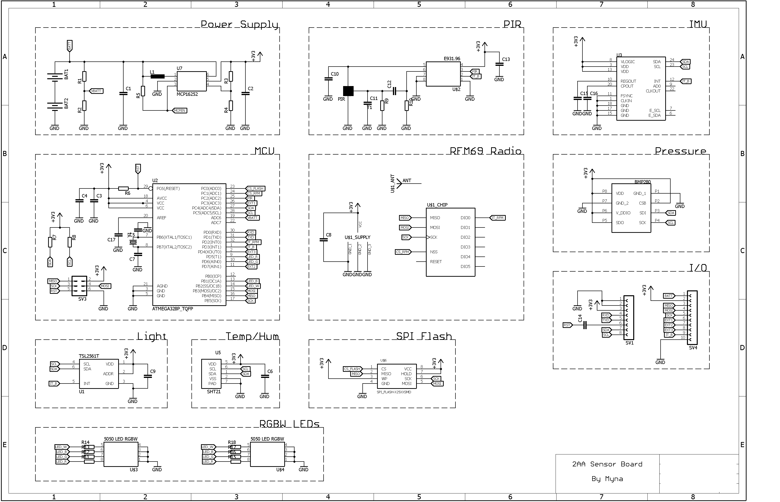
      Then I found the exotic chip E93196. It has everything in it, is low power, digital communication, and gives you a programmable interrup, for good price. Datasheet says 8µA : http://www.hsinbao.com.tw/administratorHB/caproduct_data/pdfs/E93196_12_wm IG.pdf

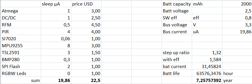
      I'm balanced between simplicity and low power choices. Standby currents for about every sensors I choose seemed "good enough" compared to the global consumption. I first tough of multiple power rails, I could go as low as 2.5V, but then I can't use the white, green and blue LEDs. Also, the performances of the radio seemed not really knowed at these levels. So I want for simplicity : one 3.3V rail, with a regulator that the MCU can bypass during sleep periods if the batteries are > 1.8V.

      The RFM chip offers AES Security, in this case, is the authentication chip still usefull ?

      Thanks ! I'm checking your work, very inspiring !

      posted in My Project
      Myna
    • RE: 2AA Sensor Board + RPI Gateway + RGBW Dimmer

      Overview of the schematics (no values yet) : sch01.png

      posted in My Project
      Myna
    • 2AA Sensor Board + RPI Gateway + RGBW Dimmer

      Hi everyone,

      I was close to buy a Fibaro complete set until I discovered MySensors Project. This project is really cool, I'd like to thanks everyone involved in it. I'm more an hardware guy, so I wanted to do a little sensor board that I can spin for 10 units or something like that to cover the needs of my apartment.

      I decided to design a little sensorboard that fit on the back of a 2AA holder ( 58*33mm) that can fit all the sensors I would need. The idea is that once you have the PCB, you solder just what you need on it. But it can work with every sensors populated also.

      After days of reading and comparing sensors / supplies solutions, these are the specifications I choose:

      • Works on two AA batteries in series. Use an MCP16252 to generate 3.3V that is enabled by default but can be switched off (and so bypassed) by the MCU if the batteries voltage is enough.
      • Battery voltage monitored by the MCU
      • Arduino compatible atmega328p design. External 512k spi flash for future OTA
      • RFM69HCW design. It seems this is better for range and overall reliability ?
      • PIR sensor: Custom design with the E931.96
      • Light sensor: TSL2591
      • Temp/Humidity sensor: Can use SI7020, HTU21D, and SHT2x range from sensirion
      • Pressure sensor: BMP280
      • IMU: MPU6050, MPU9255
      • Two RGBW 5050 LEDs
      • Extension connectors that can be used to stack extension board on top of the PCB.

      I estimated it could achieve 1 to 3 years of battery life. I try to implement every hardware energy saving possibilities (hardware interrupts, ...).

      Have you any advice or comments on this ? I have zero experience with MySensors and these sensors, so that could help. Here is a preview of the PCB : (routing still in progress). If anyone would like to see the schematics, I just need to clean it to release. This will be open source hardware if anyone is interested.

      mysens1.jpg

      Myna

      posted in My Project
      Myna