Most of Zigbee hub vendors do not want thridparty devices in there ecosystem and one is limited to what vendor allows (not to mention communication with a gateway is usually limited to vendor's app/cloud). In some cases it's possible to hack the thing to gain control (but it's fragile and hole could be closed on the next firmware update) and some home automation platforms integrate with such gateways using their cloud interface (but that is fragile construct /bad connection, cloud API change, .../). As for end devices, it depends on how far
the vendor deviated from the standard, one has to check if the device works with ones gateway or ask/write integration for it.
I use deconz raspi module with deconz frontend, a friend of mine uses deconz USB stick with Home Assistant ZHA. There are plenty of other opensource gateway implementations. And in many cases community members there help with integrating new devices (even ones that deviate from the standard), however no one will give you a guarantie that the thing would work as in many cases custom protocol extensions just reverse engineered .
I have a small zigbee zoo (~70 devices) from various vendors (xiaomi,ikea,philips,osram,tuya,phoscon,sonoff,no name,some DIY devices), which mostly works, sometimes there are routing glitches between philips/ikea bulbs and xiaomi sensors (but bulbs are really old +years, maybe it's better with newer ones). Recently whenever I'm in market for some zigbee device, I'm trying to get a Zigbee 3.0 one (hoping more strict standard compliance rules would make it easier to integrate with).
niallain
Posts
-
Zigbee gateway with support for multiple vendors? -
CNC PCB milling@NeverDie said in CNC PCB milling:
@niallain said in CNC PCB milling:
non-linearity is measured only on 1mm, with calliper or glass scale it would be possible to measure whole screw. (linuxcnc can use glass scale to map screw and then compensate, but I still don't have all components for it yet)
That's quite an interesting result! I would not have imagined it would be so bad. What exactly is happening that causes this? Is the screw being wound up almost like a spring and some kind of stiction is causing the carriage to jump about like that? Is the anti-backlash nut causing it? Or is the stepper in fact not advancing as much as it should be due to no closed-loop feedback? What's the cause? How repeatable is it? i.e. does it jump about to the same amount in the same places each time it's cycled through the test, or does it vary each time the test is repeated?
It's a great advertisement for DRO's.It might be acceptable non-linearity for trapezoidal screw. But on Y axis, at one place it was far worse (don recall exactly but around 0.1-0.05mm). I wouldn't blame steppers though as load in test case is only inertia of Z-assembly and I didn't see lost steps. Yes, It's repeatable.
From what I've read glass scale is only good enough for positioning starting point accurately (i.e. various measuring tasks), trying to add it into control loop (of linuxcnc) as encoder were considered not useful as it were too slow.
Ball screw for Y axis has finely arrived, now it's time to drill holes for new supports
and modifying moving table so that supports won't get in a way. After that it would be interesting to compare precision with X axis. -
CNC PCB milling@NeverDie
I shoot a short clip to demo following measurements- backlash :
- flex: for example I used dial gauge, since my Y screw and table are currently dismantled, so I can't show how it's done with calliper on the table
- non-linearity is measured only on 1mm, with calliper or glass scale it would be possible to measure whole screw. (linuxcnc can use glass scale to map screw and then compensate, but I still don't have all components for it yet)
-
CNC PCB milling@andrew said in CNC PCB milling:
@niallain it is 3020T which uses trapezoidal screws. "Z" uses ball screws.
you can check the "official" technical details on the item's specification (scroll down to the description then click on the "specification"):declared specs for mine were in the same ballpark as your's 3020T, modulo 8mm trapezoidal screw. But in reality that wasn't true at all, in my case cuplrit of the biggest error is the flex from the way screw nuts are attached to carriage, and the second/third are nonlinear screws (+-0.060mm) and backlash.
I'm ordered a 1204 ball screw kit for Y axis, to test how much it would reduce error.
PS:
As for testing, I just used regular digital calliper with 0.01mm resolution. -
CNC PCB milling- Does it use ball screws or trapezoidal ones?
- how stiff it is in X an Y directions?
(on my machine slight push on spindle, yields ~0.2mm of flex, and heavier one around 0.5mm, which is roughly precision I get when cutting plastic. For PCB routing error seems to stay within 0.2mm boundary) - how big is backlash
- screw (movement) linearity in X,Y planes
-
CNC PCB milling@NeverDie said in CNC PCB milling:
@niallain said in CNC PCB milling:
Eventually I've used 3d printed bar with holes for 1/4" stub bit to mount into collet
and 1/8" on other side for a scrap v-bit with probe clip attached. It allows to tram spindle in X and Y directions compared to dial gauge ( only X direction, due to not enough clerance under X axis frame)Do you have any pictures you can post?
Thanks to you, I finally 'finished' replacing arduino 'nano' with 'mega' :) , that I were putting off for a month now, since GRBL on it provides software backlash and axis skew compensations (I gave up on trying to square/fix machine mechanically).
Back to the topic, there are lots of videos on youtube where spindle is trammed using bar and paper method, so this is nothing new just a small improvement to reduce manual work and improve repeatability without expensive equipment.
Before doing it, I face spoil-board perpendicular to bar to make it level,
which results in ridges if spindle is not perpendicular to table.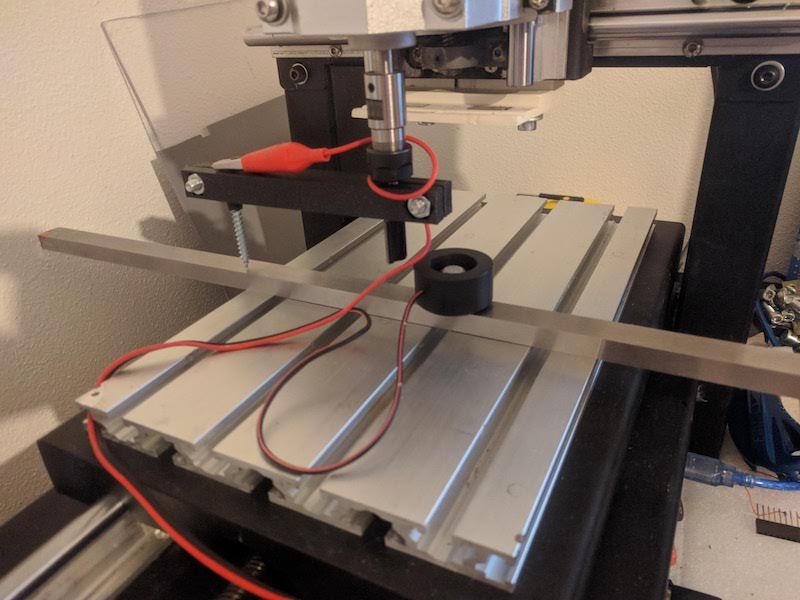
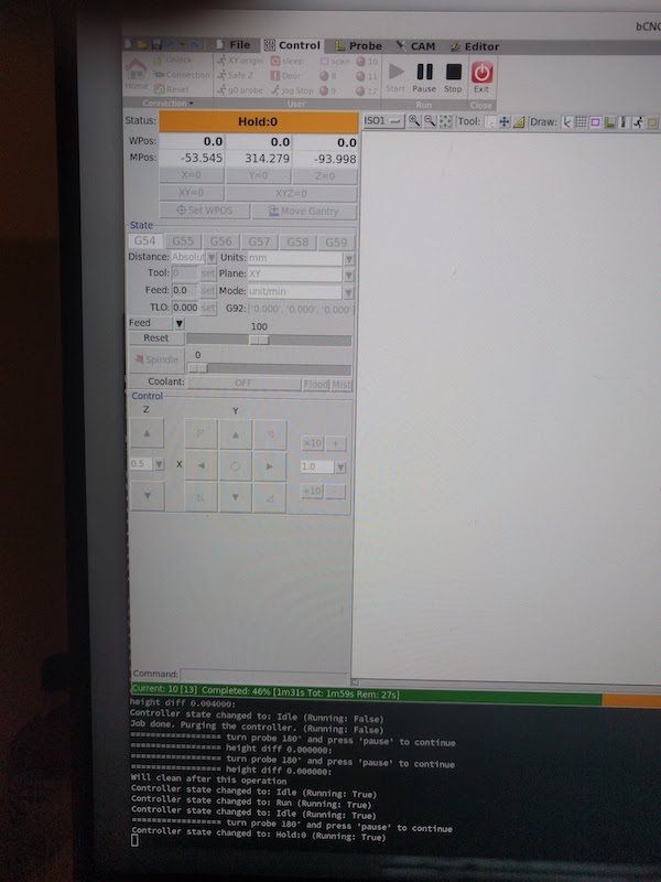
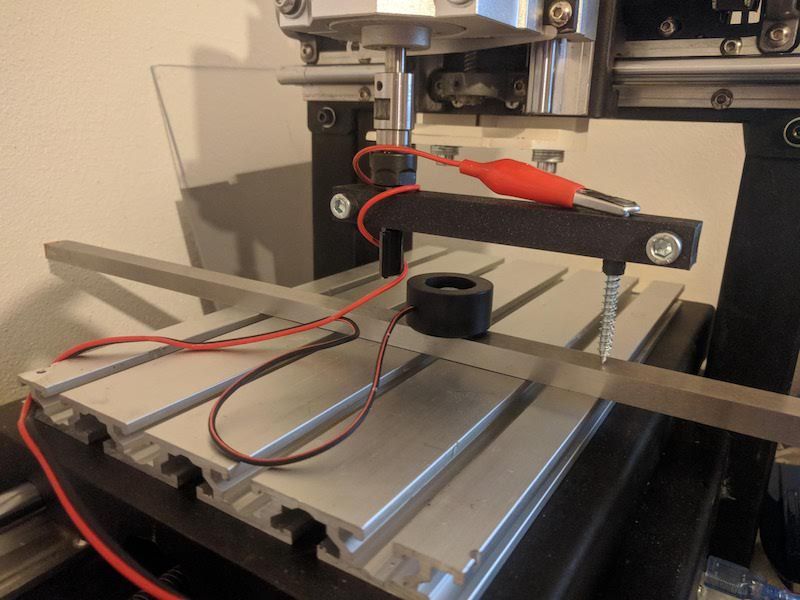
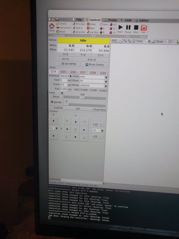
the same can be done for Y axis, just face board/turn bar 90 degrees.
Assuming you are in EU, gauge plate I got from here, it's my source for 'cheapish' but decent endmills compared to the rest of sources, I know of, within EU. -
CNC PCB milling@NeverDie said in CNC PCB milling:
so that I can do accurate repeatability tests on the z-axis, and that is because I will need to be deadnuts accurate if I am to selectively CNC mill the solder mask off from a PCB without destroying the underlying solder pads. i'm not sure I will have enough headroom on the z-axis to fit this tool into place--or use it for that matter--so I'll just have to see how that goes after it arrives. A lot may depend on how far I can plunge the dial indicators before they bottom out.
Dial based tramming depends on table being flat, otherwise result is so so.
Eventually I've used 3d printed bar with holes for 1/4" stub bit to mount into collet
and 1/8" on other side for a scrap v-bit with probe clip attached. It allows to tram spindle in X and Y directions compared to dial gauge ( only X direction, due to not enough clerance under X axis frame)Yields about the same result as dial method against uneven table almost for free. Putting MDF spoil board, and levelling, helps a bit but then one gets "waves" if the spindle is not perpendicular to the table and given that MDF is not conductive, I couldn't use probe again to re-measure.
That was solved by using steel gauge plate (I used 10x15x500mm) to serve as other end of the probe. It takes only few facing iterations to level bed with facing bit, in each direction (X and Y). Also gauge plate across whole table takes care of evening 'waves' and it's still cheaper than a good dial gauge (not speaking about dedicated tramming contraption above). Caveat is that it's much slower than using
dial gauge due to slow probing but in my case it was more repeatable so it's hard to tell which method was slower in the end.With bCNC it's possible to use gcode macro to do tedious work of probing, so one needs only to manually rotate probe 180° and press a button to see which direction axis is skewed.
-
CNC PCB milling@NeverDie I've got this one several months ago, I couldn't say it's a good one though.
here is the list of drawbacks I've had/have:- spindle fixed speed 12000RPM. I added automatic circuit breaker to it so it won't put home on fire when it rams into the table. (threw away DC connector on top as it wasn't reliably holding both sides to begin with and then it was burned a bit after spindle stall). Runout is about 50um. + whatever collet would add (cheapest ones from aliexpress were disappointment in a range 50~100um, so I've got precision one locally)
The only thing I'm going to invest into this machine is 24K spindle + vfd with small runout. (it just arrived but still unpacked, it will need adapter plate to mount it on Z plate, hopefully I'll make something with adjustable tilt to simplify tramming) - it was poor assembled, one has to disassemble and put it back properly tightening screws and making sure belts are not loose (that solved lost steps issue)
- it uses lead screws with bronze nuts like in 3D printers and a plastic spacer between nuts (to counter backlash).
- axis plates are attached to nuts via that same plastic spacer (not sure how it would do with milling aluminium)
- there was (still is) some backlash (~40-60um) left after tightening nuts,
one could tighten it further but that would come at cost of lower speeds as no-name steppers start stalling (currently I have 2300mm/min max on XY plane, and one would wish for more rapids if one would wish to try milling plastics) - squaring it is nightmare, basically the only option you have is adjusting X pillars and try to square XY and YZ at the same time (and there isn't much space to play with it). For tramming spindle on XZ plane, I had to move up one side of X support plate as there isn't sufficient play in spindle mount and then level sacrificial board to make X axis square to the table.
As result of several iterations, I've got ±40um difference in hight across the table. XY axises still not square ~0.5mm on opposite sides of of the table on X axis, but I don't have heart to repeat whole procedure again (yet). - controller dial is way too sensitive, so I practically don't use it at all. Ribbon cable to SD card fell appart, USB connector for PC doesn't work reliably (but mostly works if you got it in working position).
The whole setup was bought to prototype PCBs and later on learn how to mill other stuff (plastics/aluminium) for casing prototypes.
So far I've managed to mill reliably 0.3mm isolation paths with 60*0.2 engraving bit (but as you did, I've redesigned board with wider traces to reduce failure chances). In Flatcam, I had to add runout value to tip diameter to avoid track thinning. Perhaps I could do more fine traces now (after all the tuning) with more fragile 30 or 15 degree bits, but I won't try till I get current project out of the door (at least hardware part of it).
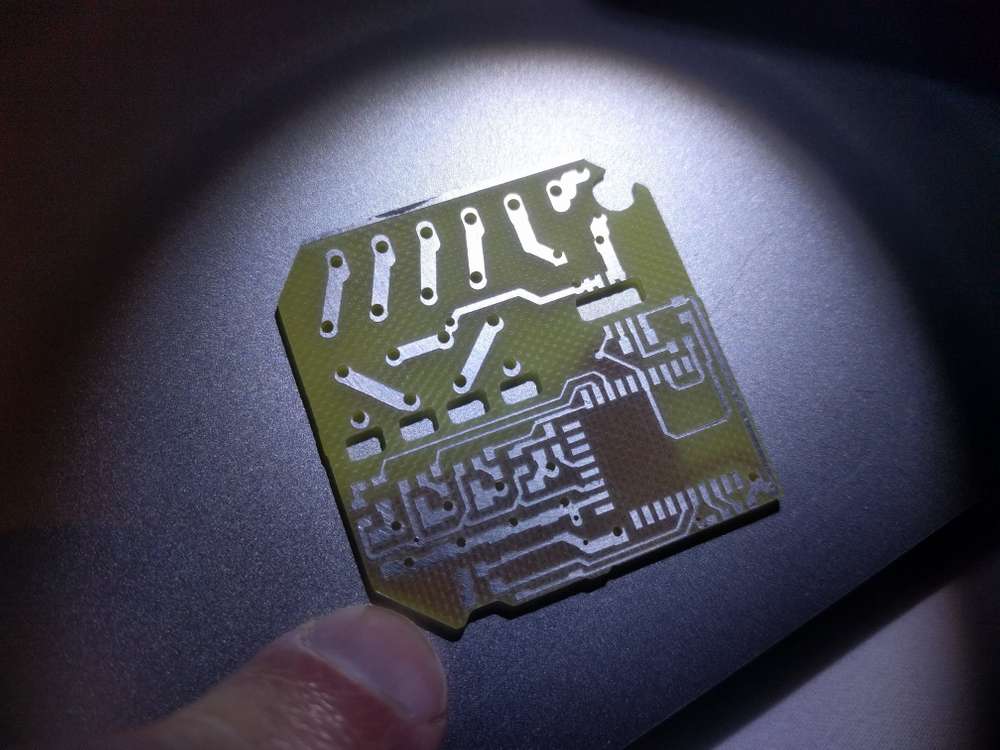
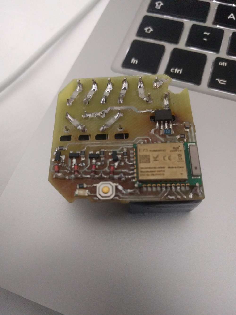
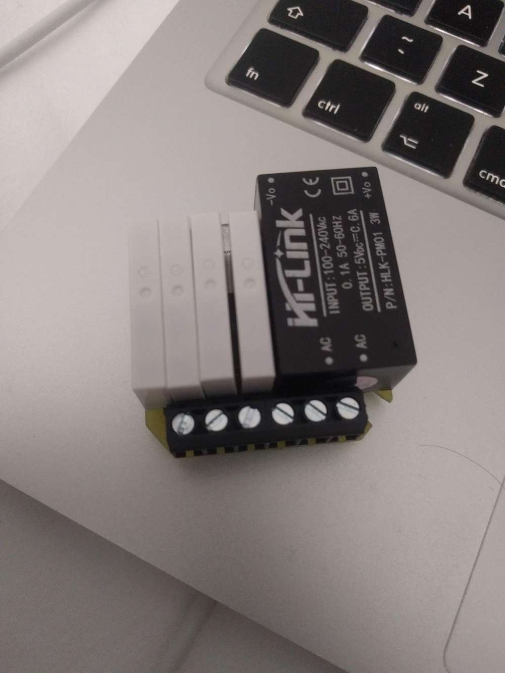
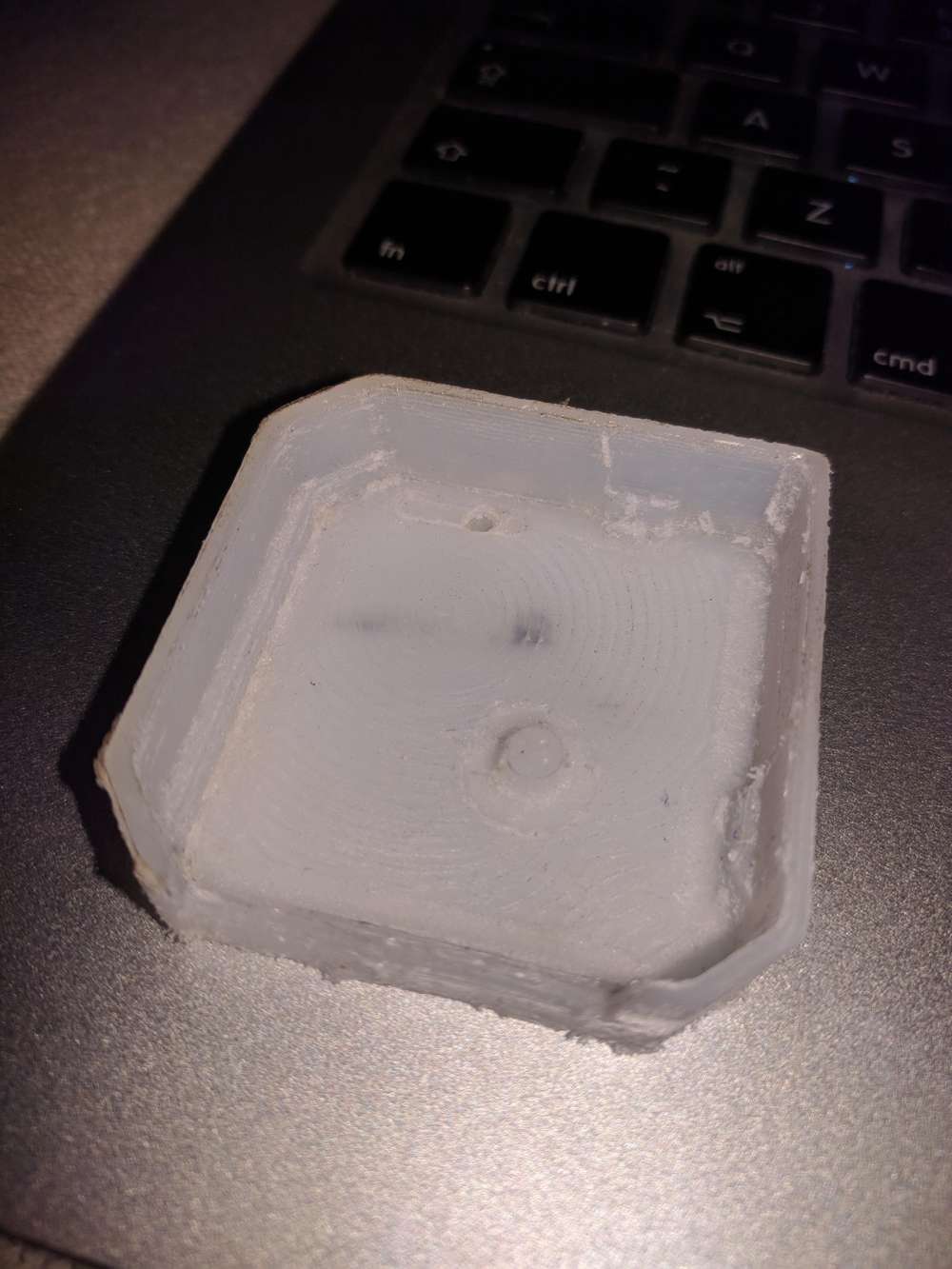
and here is my 1st attempt to mill the case part
- spindle fixed speed 12000RPM. I added automatic circuit breaker to it so it won't put home on fire when it rams into the table. (threw away DC connector on top as it wasn't reliably holding both sides to begin with and then it was burned a bit after spindle stall). Runout is about 50um. + whatever collet would add (cheapest ones from aliexpress were disappointment in a range 50~100um, so I've got precision one locally)
