I have done EXTENSIVE testing and I got it working now but I don't understand why.
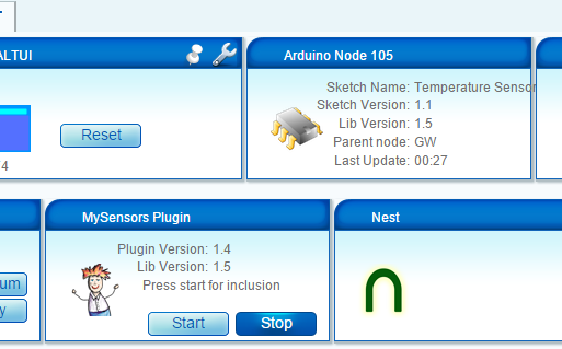
It seems like my MyConfig.h is broken which is the one which I copied over from your development package. I used one of my MyConfig.h files and the module boot was successfull and it did not crash anymore. It is stable and fully integrated into Vera with sensors now.
I also tested the different data rates. I tested 250KBPS and 1MBPS and both work fine as long as I configure the gateway and the sensor clients with the same data rate. If I use different data rates between client and gateway, the gateway does NOT crash but the sensor clients simply don't connect.
Now I have a working MyConfig.h and a broken MyConfig.h. Here is the WORKING MyConfig.h file.
/**
 * The MySensors Arduino library handles the wireless radio link and protocol
 * between your home built sensors/actuators and HA controller of choice.
 * The sensors forms a self healing radio network with optional repeaters. Each
 * repeater and gateway builds a routing tables in EEPROM which keeps track of the
 * network topology allowing messages to be routed to nodes.
 *
 * Created by Henrik Ekblad <henrik.ekblad@mysensors.org>
 * Copyright (C) 2013-2015 Sensnology AB
 * Full contributor list: https://github.com/mysensors/Arduino/graphs/contributors
 *
 * Documentation: http://www.mysensors.org
 * Support Forum: http://forum.mysensors.org
 *
 * This program is free software; you can redistribute it and/or
 * modify it under the terms of the GNU General Public License
 * version 2 as published by the Free Software Foundation.
 */


#ifndef MyConfig_h
#define MyConfig_h
#include <stdint.h>

// Enable debug flag for debug prints. This will add a lot to the size of the final sketch but good
// to see what is actually is happening when developing
//#define DEBUG
//#define MY_DEBUG_VERBOSE

// Disable this line, If you are using TX(1), RX(0) as normal I/O pin
#define ENABLED_SERIAL

// Serial output baud rate (for debug prints and serial gateway)
#define BAUD_RATE 115200


/**********************************
*  Over the air firmware updates
***********************************/

// The following define enables the safe over-the-air firmware update feature
// which requires external flash and the DualOptiBoot bootloader.
// Note: You can still have OTA FW updates without external flash but it
// requires the MYSBootloader and disabled MY_OTA_FIRMWARE_FEATURE
//#define MY_OTA_FIRMWARE_FEATURE
// Slave select pin for external flash
#define MY_OTA_FLASH_SS 8
// Flash jdecid
#define MY_OTA_FLASH_JDECID 0x1F65


/**********************************
*  Information LEDs blinking
***********************************/
// This feature enables LEDs blinking on message receive, transmit
// or if some error occured. This was commonly used only in gateways,
// but now can be used in any sensor node. Also the LEDs can now be
// disabled in the gateway.

// #define WITH_LEDS_BLINKING

// The following setting allows you to inverse the blinking feature WITH_LEDS_BLINKING
// When WITH_LEDS_BLINKING_INVERSE is enabled LEDSs are normally turned on and switches
// off when blinking

//#define WITH_LEDS_BLINKING_INVERSE


// default LEDs blinking period in milliseconds
#define DEFAULT_LED_BLINK_PERIOD 300
// The RX LED default pin
#define DEFAULT_RX_LED_PIN 6
// The TX LED default pin
#define DEFAULT_TX_LED_PIN 5
// The Error LED default pin
#define DEFAULT_ERR_LED_PIN 4


/**********************************
*  Message Signing Settings
***********************************/
// Disable to completly disable signing functionality in library
//#define MY_SIGNING_FEATURE

// Define a suitable timeout for a signature verification session
// Consider the turnaround from a nonce being generated to a signed message being received
// which might vary, especially in networks with many hops. 5s ought to be enough for anyone.
#define MY_VERIFICATION_TIMEOUT_MS 5000

// Enable to turn on whitelisting
// When enabled, a signing node will salt the signature with it's unique signature and nodeId.
// The verifying node will look up the sender in a local table of trusted nodes and
// do the corresponding salting in order to verify the signature.
// For this reason, if whitelisting is enabled on one of the nodes in a sign-verify pair, both
// nodes have to implement whitelisting for this to work.
// Note that a node can still transmit a non-salted message (i.e. have whitelisting disabled)
// to a node that has whitelisting enabled (assuming the receiver does not have a matching entry
// for the sender in it's whitelist)
//#define MY_SECURE_NODE_WHITELISTING

// MySigningAtsha204 default setting
#define MY_ATSHA204_PIN 17 // A3 - pin where ATSHA204 is attached

// MySigningAtsha204Soft default settings
#define MY_RANDOMSEED_PIN 7 // A7 - Pin used for random generation (do not connect anything to this)

// Key to use for HMAC calculation in MySigningAtsha204Soft (32 bytes)
#define MY_HMAC_KEY 0x00,0x00,0x00,0x00,0x00,0x00,0x00,0x00,0x00,0x00,0x00,0x00,0x00,0x00,0x00,0x00,0x00,0x00,0x00,0x00,0x00,0x00,0x00,0x00,0x00,0x00,0x00,0x00,0x00,0x00,0x00,0x00

/**********************************
*  NRF24L01 Driver Defaults
***********************************/
#define RF24_CE_PIN		   9
#define RF24_CS_PIN		   10
#define RF24_PA_LEVEL 	   RF24_PA_MAX
#define RF24_PA_LEVEL_GW   RF24_PA_LOW
// RF channel for the sensor net, 0-127
#define RF24_CHANNEL	   76
//RF24_250KBPS for 250kbs, RF24_1MBPS for 1Mbps, or RF24_2MBPS for 2Mbps
//#define RF24_DATARATE 	   RF24_1MBPS
#define RF24_DATARATE 	   RF24_250KBPS
// This is also act as base value for sensor nodeId addresses. Change this (or channel) if you have more than one sensor network.
#define RF24_BASE_RADIO_ID ((uint64_t)0xA8A8E1FC00LL)

// Enable SOFTSPI for NRF24L01 when using the W5100 Ethernet module
//#define SOFTSPI
#ifdef SOFTSPI
	// Define the soft SPI pins used for NRF radio
	const uint8_t SOFT_SPI_MISO_PIN = 16;
    const uint8_t SOFT_SPI_MOSI_PIN = 15;
    const uint8_t SOFT_SPI_SCK_PIN = 14;
#endif


/**********************************
*  RFM69 Driver Defaults
***********************************/
// Default network id. Use the same for all nodes that will talk to each other
#define RFM69_NETWORKID     100

// Default frequency to use. This must match the hardware version of the RFM69 radio (uncomment one):
// #define RFM69_FREQUENCY   RF69_433MHZ
#define RFM69_FREQUENCY   RF69_868MHZ
//#define FREQUENCY     RF69_915MHZ

// Enable this for encryption of packets
//#define RFM69_ENABLE_ENCRYPTION
#define RFM69_ENCRYPTKEY    "sampleEncryptKey" //exactly the same 16 characters/bytes on all nodes!


#endif
And here is the NON WORKING MyConfig.h file.
/**
 * The MySensors Arduino library handles the wireless radio link and protocol
 * between your home built sensors/actuators and HA controller of choice.
 * The sensors forms a self healing radio network with optional repeaters. Each
 * repeater and gateway builds a routing tables in EEPROM which keeps track of the
 * network topology allowing messages to be routed to nodes.
 *
 * Created by Henrik Ekblad <henrik.ekblad@mysensors.org>
 * Copyright (C) 2013-2015 Sensnology AB
 * Full contributor list: https://github.com/mysensors/Arduino/graphs/contributors
 *
 * Documentation: http://www.mysensors.org
 * Support Forum: http://forum.mysensors.org
 *
 * This program is free software; you can redistribute it and/or
 * modify it under the terms of the GNU General Public License
 * version 2 as published by the Free Software Foundation.
 */


#ifndef MyConfig_h
#define MyConfig_h
#include <stdint.h>

// Enable debug flag for debug prints. This will add a lot to the size of the final sketch but good
// to see what is actually is happening when developing
#define DEBUG

// Enable MY_DEBUG_VERBOSE flag for verbose debug prints. Requires DEBUG to be enabled.
// This will add even more to the size of the final sketch!
#define MY_DEBUG_VERBOSE

// Disable this line, If you are using TX(1), RX(0) as normal I/O pin
#define ENABLED_SERIAL

// Serial output baud rate (for debug prints and serial gateway)
#define BAUD_RATE 115200


/**********************************
*  Over the air firmware updates
***********************************/

// The following define enables the safe over-the-air firmware update feature
// which requires external flash and the DualOptiBoot bootloader.
// Note: You can still have OTA FW updates without external flash but it
// requires the MYSBootloader and disabled MY_OTA_FIRMWARE_FEATURE
//#define MY_OTA_FIRMWARE_FEATURE
// Slave select pin for external flash
#define MY_OTA_FLASH_SS 8
// Flash jdecid
#define MY_OTA_FLASH_JDECID 0x1F65


/**********************************
*  Information LEDs blinking
***********************************/
// This feature enables LEDs blinking on message receive, transmit
// or if some error occured. This was commonly used only in gateways,
// but now can be used in any sensor node. Also the LEDs can now be
// disabled in the gateway.

#define WITH_LEDS_BLINKING

// The following setting allows you to inverse the blinking feature WITH_LEDS_BLINKING
// When WITH_LEDS_BLINKING_INVERSE is enabled LEDSs are normally turned on and switches
// off when blinking

//#define WITH_LEDS_BLINKING_INVERSE


// default LEDs blinking period in milliseconds
#define DEFAULT_LED_BLINK_PERIOD 300
// The RX LED default pin
#define DEFAULT_RX_LED_PIN 6
// The TX LED default pin
#define DEFAULT_TX_LED_PIN 5
// The Error LED default pin
#define DEFAULT_ERR_LED_PIN 4


/**********************************
*  Message Signing Settings
***********************************/
// Disable to completly disable signing functionality in library
//#define MY_SIGNING_FEATURE

// Define a suitable timeout for a signature verification session
// Consider the turnaround from a nonce being generated to a signed message being received
// which might vary, especially in networks with many hops. 5s ought to be enough for anyone.
#define MY_VERIFICATION_TIMEOUT_MS 5000

// Enable to turn on whitelisting
// When enabled, a signing node will salt the signature with it's unique signature and nodeId.
// The verifying node will look up the sender in a local table of trusted nodes and
// do the corresponding salting in order to verify the signature.
// For this reason, if whitelisting is enabled on one of the nodes in a sign-verify pair, both
// nodes have to implement whitelisting for this to work.
// Note that a node can still transmit a non-salted message (i.e. have whitelisting disabled)
// to a node that has whitelisting enabled (assuming the receiver does not have a matching entry
// for the sender in it's whitelist)
//#define MY_SECURE_NODE_WHITELISTING

// MySigningAtsha204 default setting
#define MY_ATSHA204_PIN 17 // A3 - pin where ATSHA204 is attached

// MySigningAtsha204Soft default settings
#define MY_RANDOMSEED_PIN 7 // A7 - Pin used for random generation (do not connect anything to this)

// Key to use for HMAC calculation in MySigningAtsha204Soft (32 bytes)
#define MY_HMAC_KEY 0x00,0x00,0x00,0x00,0x00,0x00,0x00,0x00,0x00,0x00,0x00,0x00,0x00,0x00,0x00,0x00,0x00,0x00,0x00,0x00,0x00,0x00,0x00,0x00,0x00,0x00,0x00,0x00,0x00,0x00,0x00,0x00

/**********************************
*  NRF24L01 Driver Defaults
***********************************/
#define RF24_CE_PIN		   9
#define RF24_CS_PIN		   10
#define RF24_PA_LEVEL 	   RF24_PA_MAX
#define RF24_PA_LEVEL_GW   RF24_PA_LOW
// RF channel for the sensor net, 0-127
#define RF24_CHANNEL	   76
//RF24_250KBPS for 250kbs, RF24_1MBPS for 1Mbps, or RF24_2MBPS for 2Mbps
#define RF24_DATARATE 	   RF24_250KBPS
// This is also act as base value for sensor nodeId addresses. Change this (or channel) if you have more than one sensor network.
#define RF24_BASE_RADIO_ID ((uint64_t)0xA8A8E1FC00LL)

// Enable SOFTSPI for NRF24L01 when using the W5100 Ethernet module
//#define SOFTSPI
#ifdef SOFTSPI
	// Define the soft SPI pins used for NRF radio
	const uint8_t SOFT_SPI_MISO_PIN = 16;
    const uint8_t SOFT_SPI_MOSI_PIN = 15;
    const uint8_t SOFT_SPI_SCK_PIN = 14;
#endif


/**********************************
*  RFM69 Driver Defaults
***********************************/
// Default network id. Use the same for all nodes that will talk to each other
#define RFM69_NETWORKID     100

// Default frequency to use. This must match the hardware version of the RFM69 radio (uncomment one):
// #define RFM69_FREQUENCY   RF69_433MHZ
#define RFM69_FREQUENCY   RF69_868MHZ
//#define FREQUENCY     RF69_915MHZ

// Enable this for encryption of packets
//#define RFM69_ENABLE_ENCRYPTION
#define RFM69_ENCRYPTKEY    "sampleEncryptKey" //exactly the same 16 characters/bytes on all nodes!

#endif
I don't understand why the second one makes the module reboot constantly. However, I am happy now that it is working but I wanted to share my experience and maybe it can help others to troubleshoot this and understand why this was happening as I am sure I will not be the only one having that issue in the future.
I do appreciate all the help so far and I wouldn't have been able to solve it without your help Yveaux. THANK YOU!!!