@virtualmkr
I cant connect to arduino again. I ping ip from my laptop and its ok.
Error in HA is "cannot make connection"
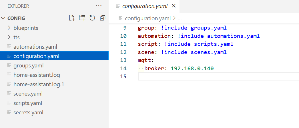
I installed file editor and i dont have such a folder and file.
P
PZDPRO
@PZDPRO
Posts
-
Arduino+M5100 cannot connect to LAN -
Arduino+M5100 cannot connect to LAN@virtualmkr Hello!
I checked and i think i dont have any file from mysensors.
I'm not good at programming and i only change ready skatches. Maybe you can be my guide how to start with this?
Main thing for me is to have arduino as a light controller. To analogs i have connected monostable switches and on digitals outputs a i had connected relays. In domoticz it works very well via USB. -
Arduino+M5100 cannot connect to LAN@mfalkvidd OK.
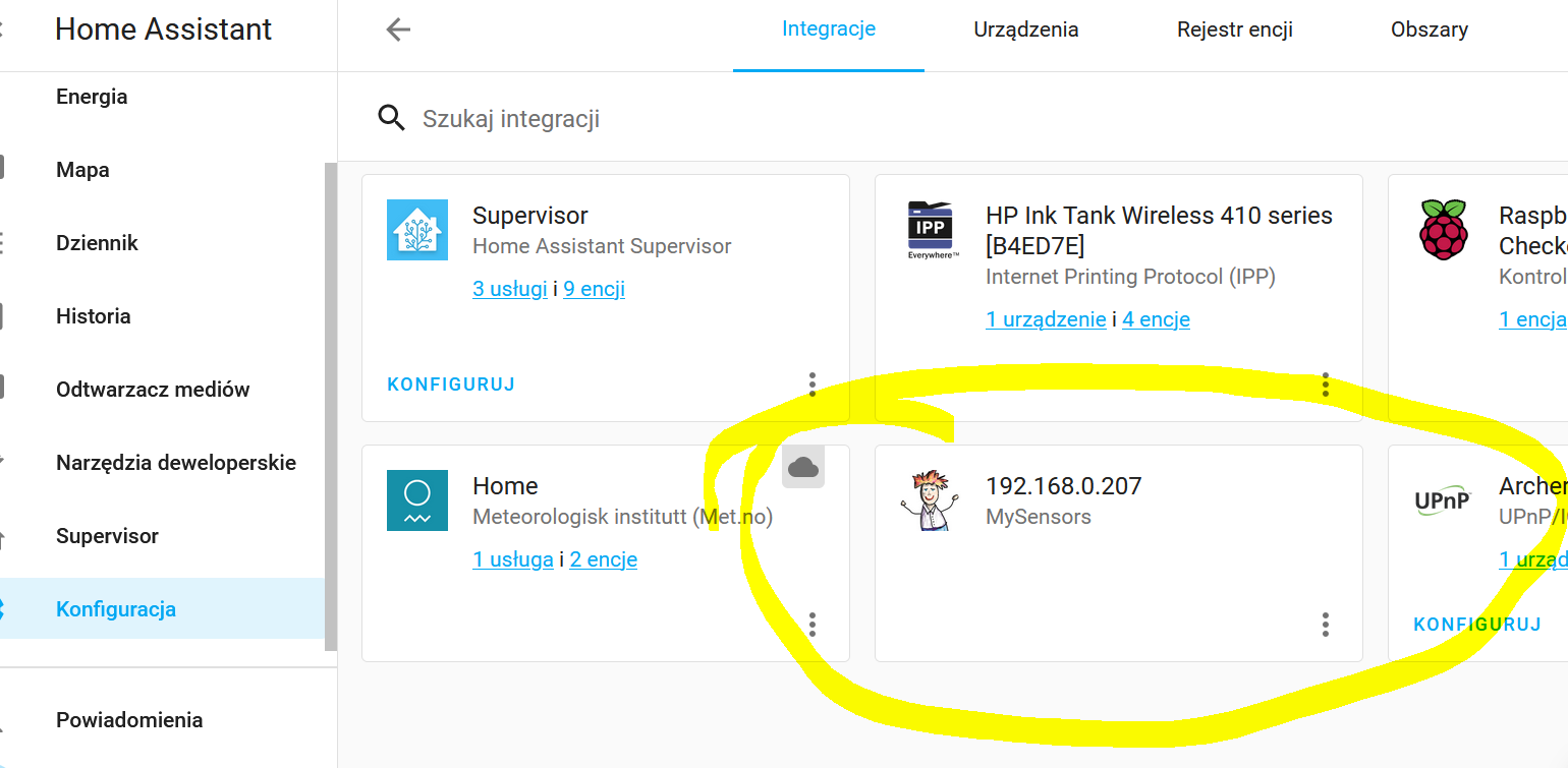
I changed my sketch and finally i connect it to HA using integration but still dont have any device in HA.
code_text // Enable debug prints to serial monitor #define MY_DEBUG // Enable and select radio type attached //#define MY_RADIO_RF24 //#define MY_RADIO_NRF5_ESB //#define MY_RADIO_RFM69 //#define MY_RADIO_RFM95 // Enable gateway ethernet module type #define MY_GATEWAY_W5100 // W5100 Ethernet module SPI enable (optional if using a shield/module that manages SPI_EN signal) //#define MY_W5100_SPI_EN 4 // Enable Soft SPI for NRF radio (note different radio wiring is required) // The W5100 ethernet module seems to have a hard time co-operate with // radio on the same spi bus. #if !defined(MY_W5100_SPI_EN) && !defined(ARDUINO_ARCH_SAMD) #define MY_SOFTSPI #define MY_SOFT_SPI_SCK_PIN 14 #define MY_SOFT_SPI_MISO_PIN 16 #define MY_SOFT_SPI_MOSI_PIN 15 #endif // When W5100 is connected we have to move CE/CSN pins for NRF radio #ifndef MY_RF24_CE_PIN #define MY_RF24_CE_PIN 5 #endif #ifndef MY_RF24_CS_PIN #define MY_RF24_CS_PIN 6 #endif // Enable UDP communication //#define MY_USE_UDP // If using UDP you need to set MY_CONTROLLER_IP_ADDRESS or MY_CONTROLLER_URL_ADDRESS below // Enable MY_IP_ADDRESS here if you want a static ip address (no DHCP) #define MY_IP_ADDRESS 192,168,0,207 // If using static ip you can define Gateway and Subnet address as well #define MY_IP_GATEWAY_ADDRESS 192,168,0,1 #define MY_IP_SUBNET_ADDRESS 255,255,255,0 // Renewal period if using DHCP //#define MY_IP_RENEWAL_INTERVAL 60000 // The port to keep open on node server mode / or port to contact in client mode #define MY_PORT 5003 // Controller ip address. Enables client mode (default is "server" mode). // Also enable this if MY_USE_UDP is used and you want sensor data sent somewhere. #define MY_CONTROLLER_IP_ADDRESS 192, 168, 0, 140 //#define MY_CONTROLLER_URL_ADDRESS "my.controller.org" // The MAC address can be anything you want but should be unique on your network. // Newer boards have a MAC address printed on the underside of the PCB, which you can (optionally) use. // Note that most of the Arduino examples use "DEAD BEEF FEED" for the MAC address. #define MY_MAC_ADDRESS 0xDE, 0xAD, 0xBE, 0xEF, 0xFE, 0xED // Enable inclusion mode #define MY_INCLUSION_MODE_FEATURE // Enable Inclusion mode button on gateway //#define MY_INCLUSION_BUTTON_FEATURE // Set inclusion mode duration (in seconds) #define MY_INCLUSION_MODE_DURATION 60 // Digital pin used for inclusion mode button //#define MY_INCLUSION_MODE_BUTTON_PIN 3 // Set blinking period #define MY_DEFAULT_LED_BLINK_PERIOD 300 // Flash leds on rx/tx/err // Uncomment to override default HW configurations //#define MY_DEFAULT_ERR_LED_PIN 7 // Error led pin //#define MY_DEFAULT_RX_LED_PIN 8 // Receive led pin //#define MY_DEFAULT_TX_LED_PIN 9 // Transmit led pin #if defined(MY_USE_UDP) #include <EthernetUdp.h> #endif #include <Ethernet.h> #include <MySensors.h> #include <Bounce2.h> #define MY_REPEATER_FEATURE #define MY_NODE_ID 1 #include <SPI.h> // Enable repeater functionality for this node #define MY_REPEATER_FEATURE #define RELAY_PIN 5 #define BUTTON_PIN 3 #define CHILD_ID 1 #define RELAY_ON 1 #define RELAY_OFF 0 Bounce debouncer = Bounce(); bool state = false; bool initialValueSent = false; MyMessage msg(CHILD_ID, V_STATUS); void setup() { pinMode(BUTTON_PIN, INPUT_PULLUP); debouncer.attach(BUTTON_PIN); debouncer.interval(10); // Make sure relays are off when starting up digitalWrite(RELAY_PIN, RELAY_OFF); pinMode(RELAY_PIN, OUTPUT); } void presentation() { sendSketchInfo("Relay+button", "1.0"); present(CHILD_ID, S_BINARY); } void loop() { if (!initialValueSent) { Serial.println("Sending initial value"); send(msg.set(state?RELAY_ON:RELAY_OFF)); Serial.println("Requesting initial value from controller"); request(CHILD_ID, V_STATUS); wait(2000, C_SET, V_STATUS); } if (debouncer.update()) { if (debouncer.read()==LOW) { state = !state; // Send new state and request ack back send(msg.set(state?RELAY_ON:RELAY_OFF), true); } } } void receive(const MyMessage &message) { if (message.isAck()) { Serial.println("This is an ack from gateway"); } if (message.type == V_STATUS) { if (!initialValueSent) { Serial.println("Receiving initial value from controller"); initialValueSent = true; } // Change relay state state = (bool)message.getInt(); digitalWrite(RELAY_PIN, state?RELAY_ON:RELAY_OFF); send(msg.set(state?RELAY_ON:RELAY_OFF)); } } -
Arduino+M5100 cannot connect to LANThank you @mfalkvidd
Do i need this radio module even if i use wire system in my home?
-
Arduino+M5100 cannot connect to LAN@mfalkvidd
This is what i have:
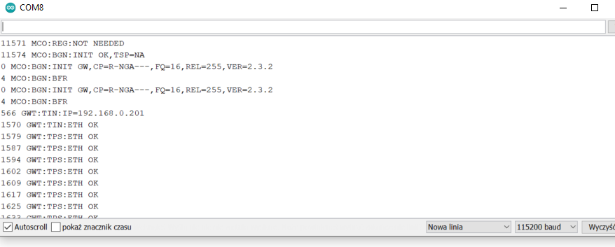
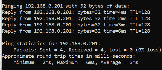
I cant see arduino in my router internal website, but i made a ping wrom Command line and i have this:
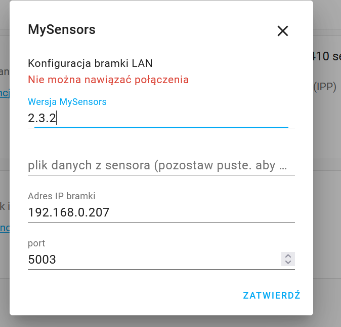
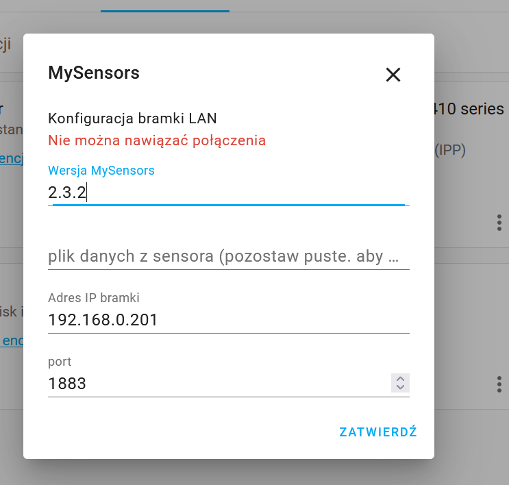
Unfortunatelly i cant connect it in HA:
-
Arduino+M5100 cannot connect to LAN@mfalkvidd Hi,
I tried this but still cannot connect to my LAN network. Router doesn't give me IP. I cannot see arduino in HA.
I tried many configurations. Even i put a new sketches from my sensors examples in arduino IDE (GatewayW5100 and GatewayW5100Client).Maybe you someone have working sketch for tests?
Thank you in advance.
-
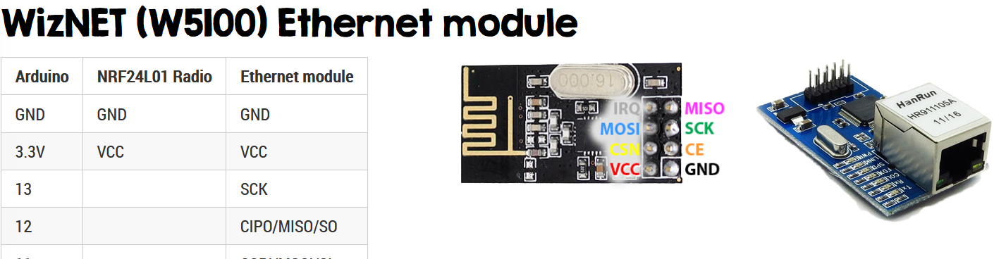
Arduino+M5100 cannot connect to LAN@mfalkvidd
Yes. I use this:
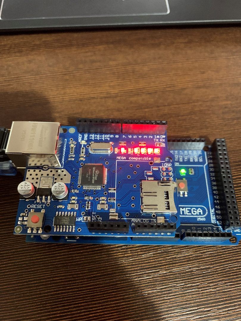
It shouldn't be wired wrong. -
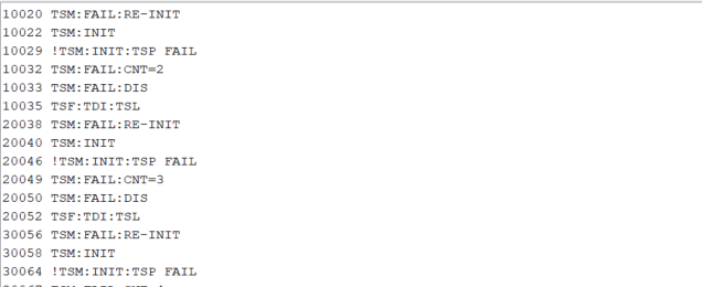
Arduino+M5100 cannot connect to LANHello Mfalkvidd!
Thank you for your post. I checked your link and can't find any answer for my problem.
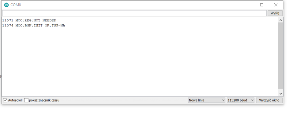
Here is what i get:
-
Arduino+M5100 cannot connect to LANDears,
I use Arduino Mega and M5100 ethernet Shield. I put prepared sketch but it won't connect to my local LAN. Could you please check my sketch?code_text/* * The MySensors Arduino library handles the wireless radio link and protocol * between your home built sensors/actuators and HA controller of choice. * The sensors forms a self healing radio network with optional repeaters. Each * repeater and gateway builds a routing tables in EEPROM which keeps track of the * network topology allowing messages to be routed to nodes. * * Created by Henrik Ekblad <henrik.ekblad@mysensors.org> * Copyright (C) 2013-2019 Sensnology AB * Full contributor list: https://github.com/mysensors/MySensors/graphs/contributors * * Documentation: http://www.mysensors.org * Support Forum: http://forum.mysensors.org * * This program is free software; you can redistribute it and/or * modify it under the terms of the GNU General Public License * version 2 as published by the Free Software Foundation. * ******************************* * * REVISION HISTORY * Version 1.0 - Henrik Ekblad * Contribution by a-lurker and Anticimex * Contribution by Norbert Truchsess <norbert.truchsess@t-online.de> * Contribution by Tomas Hozza <thozza@gmail.com> * * * DESCRIPTION * The EthernetGateway sends data received from sensors to the ethernet link. * The gateway also accepts input on ethernet interface, which is then sent out to the radio network. * * The GW code is designed for Arduino 328p / 16MHz. ATmega168 does not have enough memory to run this program. * * LED purposes: * - To use the feature, uncomment MY_DEFAULT_xxx_LED_PIN in the sketch below * - RX (green) - blink fast on radio message received. In inclusion mode will blink fast only on presentation received * - TX (yellow) - blink fast on radio message transmitted. In inclusion mode will blink slowly * - ERR (red) - fast blink on error during transmission error or receive crc error * * See http://www.mysensors.org/build/ethernet_gateway for wiring instructions. * */ // Enable debug prints to serial monitor #define MY_DEBUG // Enable and select radio type attached #define MY_RADIO_RF24 //#define MY_RADIO_NRF5_ESB //#define MY_RADIO_RFM69 //#define MY_RADIO_RFM95 // Enable gateway ethernet module type #define MY_GATEWAY_W5100 // W5100 Ethernet module SPI enable (optional if using a shield/module that manages SPI_EN signal) //#define MY_W5100_SPI_EN 4 // Enable Soft SPI for NRF radio (note different radio wiring is required) // The W5100 ethernet module seems to have a hard time co-operate with // radio on the same spi bus. #if !defined(MY_W5100_SPI_EN) && !defined(ARDUINO_ARCH_SAMD) #define MY_SOFTSPI #define MY_SOFT_SPI_SCK_PIN 14 #define MY_SOFT_SPI_MISO_PIN 16 #define MY_SOFT_SPI_MOSI_PIN 15 #endif // When W5100 is connected we have to move CE/CSN pins for NRF radio #ifndef MY_RF24_CE_PIN #define MY_RF24_CE_PIN 5 #endif #ifndef MY_RF24_CS_PIN #define MY_RF24_CS_PIN 6 #endif // Enable UDP communication //#define MY_USE_UDP // If using UDP you need to set MY_CONTROLLER_IP_ADDRESS or MY_CONTROLLER_URL_ADDRESS below // Enable MY_IP_ADDRESS here if you want a static ip address (no DHCP) #define MY_IP_ADDRESS 192,168,0,201 // If using static ip you can define Gateway and Subnet address as well #define MY_IP_GATEWAY_ADDRESS 192,168,0,1 #define MY_IP_SUBNET_ADDRESS 255,255,255,0 // Renewal period if using DHCP //#define MY_IP_RENEWAL_INTERVAL 60000 // The port to keep open on node server mode / or port to contact in client mode #define MY_PORT 5003 // Controller ip address. Enables client mode (default is "server" mode). // Also enable this if MY_USE_UDP is used and you want sensor data sent somewhere. //#define MY_CONTROLLER_IP_ADDRESS 192, 168, 178, 254 //#define MY_CONTROLLER_URL_ADDRESS "my.controller.org" // The MAC address can be anything you want but should be unique on your network. // Newer boards have a MAC address printed on the underside of the PCB, which you can (optionally) use. // Note that most of the Arduino examples use "DEAD BEEF FEED" for the MAC address. #define MY_MAC_ADDRESS 0xDE, 0xAD, 0xBE, 0xEF, 0xFE, 0xED // Enable inclusion mode #define MY_INCLUSION_MODE_FEATURE // Enable Inclusion mode button on gateway //#define MY_INCLUSION_BUTTON_FEATURE // Set inclusion mode duration (in seconds) #define MY_INCLUSION_MODE_DURATION 60 // Digital pin used for inclusion mode button //#define MY_INCLUSION_MODE_BUTTON_PIN 3 // Set blinking period #define MY_DEFAULT_LED_BLINK_PERIOD 300 // Flash leds on rx/tx/err // Uncomment to override default HW configurations //#define MY_DEFAULT_ERR_LED_PIN 7 // Error led pin //#define MY_DEFAULT_RX_LED_PIN 8 // Receive led pin //#define MY_DEFAULT_TX_LED_PIN 9 // Transmit led pin #if defined(MY_USE_UDP) #include <EthernetUdp.h> #endif #include <Ethernet.h> #include <MySensors.h> #include <Bounce2.h> // Enable repeater functionality for this node #define MY_REPEATER_FEATURE #define RELAY_LA_01 4 // Arduino Digital I/O pin number for first relay (second on pin+1 etc) #define RELAY_LA_02 5 #define RELAY_LA_03 6 #define RELAY_LA_04 7 #define RELAY_LA_05 8 #define RELAY_LA_06 9 #define RELAY_LA_07 10 #define RELAY_LA_08 11 #define RELAY_LA_09 12 #define RELAY_LA_10 13 #define NUMBER_OF_RELAYS 10 // Total number of attached relays #define RELAY_ON 0 // GPIO value to write to turn on attached relay #define RELAY_OFF 1 // GPIO value to write to turn off attached relay #define LA_01 A1 #define LA_02 A2 #define LA_03 A3 #define LA_04 A4 #define LA_05 A5 #define LA_06 A6 #define LA_07 A7 #define LA_08 A8 #define LA_09 A9 #define LA_10 A10 void before() { for (int sensor=1, pin=RELAY_LA_01; sensor<=NUMBER_OF_RELAYS;sensor++, pin++) { // Then set relay pins in output mode pinMode(pin, OUTPUT); // Set relay to last known state (using eeprom storage) digitalWrite(pin, loadState(sensor)?RELAY_ON:RELAY_OFF); } } Bounce debouncer = Bounce(); Bounce debouncer2 = Bounce(); Bounce debouncer3 = Bounce(); Bounce debouncer4 = Bounce(); Bounce debouncer5 = Bounce(); Bounce debouncer6 = Bounce(); Bounce debouncer7 = Bounce(); Bounce debouncer8 = Bounce(); Bounce debouncer9 = Bounce(); Bounce debouncer10 = Bounce(); void setup() { // Setup locally attached sensors delay(10000); // Setup the button. pinMode(LA_01, INPUT_PULLUP); pinMode(LA_02, INPUT_PULLUP); pinMode(LA_03, INPUT_PULLUP); pinMode(LA_04, INPUT_PULLUP); pinMode(LA_05, INPUT_PULLUP); pinMode(LA_06, INPUT_PULLUP); pinMode(LA_07, INPUT_PULLUP); pinMode(LA_08, INPUT_PULLUP); pinMode(LA_09, INPUT_PULLUP); pinMode(LA_10, INPUT_PULLUP); // After setting up the button, setup debouncer. debouncer.attach(LA_01); debouncer.interval(5); debouncer2.attach(LA_02); debouncer2.interval(5); debouncer3.attach(LA_03); debouncer3.interval(5); debouncer4.attach(LA_04); debouncer4.interval(5); debouncer5.attach(LA_05); debouncer5.interval(5); debouncer6.attach(LA_06); debouncer6.interval(5); debouncer7.attach(LA_07); debouncer7.interval(5); debouncer8.attach(LA_08); debouncer8.interval(5); debouncer9.attach(LA_09); debouncer9.interval(5); debouncer10.attach(LA_10); debouncer10.interval(5); //presentation(); } void presentation() { // Send the sketch version information to the gateway and Controller sendSketchInfo("Relay", "1.0"); for (int sensor=1, pin=RELAY_LA_01; sensor<=NUMBER_OF_RELAYS;sensor++, pin++) { // Register all sensors to gw (they will be created as child devices) present(sensor, S_LIGHT); } } MyMessage msg(1, V_LIGHT); MyMessage msg2(2, V_LIGHT); MyMessage msg3(3, V_LIGHT); MyMessage msg4(4, V_LIGHT); MyMessage msg5(5, V_LIGHT); MyMessage msg6(6, V_LIGHT); MyMessage msg7(7, V_LIGHT); MyMessage msg8(8, V_LIGHT); MyMessage msg9(9, V_LIGHT); MyMessage msg10(10, V_LIGHT); void loop() { // Send locally attached sensor data here if (debouncer.update()) { // Get the update value. int value = debouncer.read(); // Send in the new value. if(value == LOW){ saveState(1, !loadState(1)); digitalWrite(RELAY_LA_01, loadState(1)?RELAY_ON:RELAY_OFF); send(msg.set(loadState(1))); } } if (debouncer2.update()) { int value2 = debouncer2.read(); if(value2 == LOW){ saveState(2, !loadState(2)); digitalWrite(RELAY_LA_02, loadState(2)?RELAY_ON:RELAY_OFF); send(msg2.set(loadState(2))); } } if (debouncer3.update()) { // Get the update value. int value3 = debouncer3.read(); // Send in the new value. if(value3 == LOW){ saveState(3, !loadState(3)); digitalWrite(RELAY_LA_03, loadState(3)?RELAY_ON:RELAY_OFF); send(msg3.set(loadState(3))); } } if (debouncer4.update()) { // Get the update value. int value4 = debouncer4.read(); // Send in the new value. if(value4 == LOW){ saveState(4, !loadState(4)); digitalWrite(RELAY_LA_04, loadState(4)?RELAY_ON:RELAY_OFF); send(msg4.set(loadState(4))); } } if (debouncer5.update()) { // Get the update value. int value5 = debouncer5.read(); // Send in the new value. if(value5 == LOW){ saveState(5, !loadState(5)); digitalWrite(RELAY_LA_05, loadState(5)?RELAY_ON:RELAY_OFF); send(msg5.set(loadState(5))); } } if (debouncer6.update()) { // Get the update value. int value6 = debouncer6.read(); // Send in the new value. if(value6 == LOW){ saveState(6, !loadState(6)); digitalWrite(RELAY_LA_06, loadState(6)?RELAY_ON:RELAY_OFF); send(msg6.set(loadState(6))); } } if (debouncer7.update()) { // Get the update value. int value7 = debouncer7.read(); // Send in the new value. if(value7 == LOW){ saveState(7, !loadState(7)); digitalWrite(RELAY_LA_07, loadState(7)?RELAY_ON:RELAY_OFF); send(msg7.set(loadState(7))); } } if (debouncer8.update()) { // Get the update value. int value8 = debouncer8.read(); // Send in the new value. if(value8 == LOW){ saveState(8, !loadState(8)); digitalWrite(RELAY_LA_08, loadState(8)?RELAY_ON:RELAY_OFF); send(msg8.set(loadState(8))); } } if (debouncer9.update()) { // Get the update value. int value9 = debouncer9.read(); // Send in the new value. if(value9 == LOW){ saveState(9, !loadState(9)); digitalWrite(RELAY_LA_09, loadState(9)?RELAY_ON:RELAY_OFF); send(msg9.set(loadState(9))); } } if (debouncer10.update()) { // Get the update value. int value10 = debouncer10.read(); // Send in the new value. if(value10 == LOW){ saveState(10, !loadState(10)); digitalWrite(RELAY_LA_10, loadState(10)?RELAY_ON:RELAY_OFF); send(msg10.set(loadState(10))); } } } void receive(const MyMessage &message) { // We only expect one type of message from controller. But we better check anyway. if (message.type==V_LIGHT) { // Change relay state digitalWrite(message.sensor-1+RELAY_LA_01, message.getBool()?RELAY_ON:RELAY_OFF); // Store state in eeprom saveState(message.sensor, message.getBool()); // Write some debug info Serial.print("Incoming change for sensor:"); Serial.print(message.sensor); Serial.print(", New status: "); Serial.println(message.getBool()); } }