Navigation

    • Register
    • Login
    • Search
    • OpenHardware.io
    • Categories
    • Recent
    • Tags
    • Popular
    1. Home
    2. Rpx
    3. Posts
    • Profile
    • Following
    • Followers
    • Topics
    • Posts
    • Best
    • Groups

    Posts made by Rpx

    • RE: W5100 Ethernet module PoE

      Hi, sorry for the delay, I had just read your post and I could said "me too"
      But I solved the problem and it works for two years now.
      I explain my solution here, if the French don't afraid you.
      https://easydomoticz.com/forum/viewtopic.php?f=20&t=6497
      I resume, a 7.5volts power supply, a passive injector, and a spécial home-made cable to bypass the RJ45 socket. The 7.5 v go to Vin-Gnd of the Nano to produce 5v wich is returned to the W5100. QED.

      Rpx.

      posted in Hardware
      Rpx
      Rpx
    • RE: nRF24Doctor

      @rpx
      @Yveaux OK with a nRF24 gateway it's working fine. But, and I don't remember why, I need to strap pin 8 of nRF24L01+ (Irq) to Nano Pin D2, which is not required on mysensors gateways.
      And with MySensors Library 2.3.0 beta Scan is working.

      0_1543167158653_IMG_3114-Scan2.jpg
      This pattern is a 950W microwave owen near by 0,60 meter.
      The graph has 8 pixel high, can you give me a idea of the power scale of each pixel ?

      And I plan with friends help, to measure differents antennas in open field as J pole, Yagi-Uda and cloverleaf.
      Rpx.

      posted in My Project
      Rpx
      Rpx
    • RE: nRF24Doctor

      @yveaux Thanks !

      One enclosure later...
      I think about my three gateways weren't view.
      And made few adjustments.

      First in RadioConfig.h Ireplace "Zero CaFe BaBe" by my one of MY_RF24_BASE_RADIO_ID

      /**

      • @def MY_RF24_BASE_RADIO_ID
      • @brief RF24 radio network identifier.
      • This acts as base value for sensor nodeId addresses. Change this (or channel) if you have more
      • than one sensor network.
        */
        //0x00,0xCA,0xFE,0xBA,0xBE // modif Rpx de "Zero CaFe BaBe"

      Second to be sure force selection of nRF24 CE on D9 and CS on D10

      //PIN 9~13: NRF24 RADIO
      #define MY_RF24_CE_PIN    (9)
      #define MY_RF24_CS_PIN    (10)
      

      And then Doctor is at work!
      Enclosure Open
      0_1538944058648_IMG_3100-1024x1024.jpg

      Connecting
      0_1538944136354_nRF24DoctorConnection.png

      Msg
      0_1538944177764_nRF24DoctorMsg.png

      Message Count
      0_1538944217920_nRF24DoctorMessageCount.png

      Tx Rx
      0_1538944257770_nRF24DoctorRxTx.png

      Sleep
      0_1538944291576_nRF24DoctorSleep.png

      Scan
      0_1538944474986_nRF24DoctorScan.png

      At last, nRF24Doctor is working. Except scan due I think to use MySensors Library 2.2.0.
      I don't know if a nRF24 PA LNA (20dBm) can be tested with nRF24Doctor but if my circuit design is used you should change LE33 witch output max 100mA because nRF24 PA LNA need 150mA min.
      And one problem, a test with nRF24Doctor "freeze" Domoticz 3.8153, I need to stop service Domoticz and start to have a Domoticz web access.

      Thank you very much Yveaux.
      Rpx.

      posted in My Project
      Rpx
      Rpx
    • RE: nRF24Doctor

      @Yveaux
      Thank you very much for your answer.
      I upload nRF24DoctorNode.ino with commented line and ... It work's ! But it don't see any of my three gateways one serial and two Ethernet W5100 which are all on work.
      First I have to build a fourth one with the nRF24DoctorGateway.ino sketch.
      Some photos:
      Front
      0_1538577849772_IMG_3094-1024x1024.jpg
      Front without Nano & LCD
      0_1538577902996_IMG_3096-1024x1024.jpg
      Back
      0_1538578009930_IMG_3097-1024x1024.jpg
      KiKad schematics:

      0_1538652376382_nRF24Doctor_v2_sch_l.png
      Pcb:
      0_1538578266648_nRF24Doctor_v2-brd.png
      And LCD modifications:

      For D4 - D7 LCD
      #define LCD_D7     8  // 5 due to easier pcb design 
      #define LCD_D6     7  // 6
      #define LCD_D5     6  // 7
      #define LCD_D4     5  // 8
      

      At last, I need to build an enclosure...

      Rpx.

      posted in My Project
      Rpx
      Rpx
    • RE: nRF24Doctor

      @Yveaux

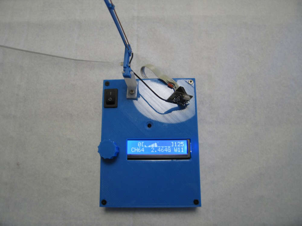
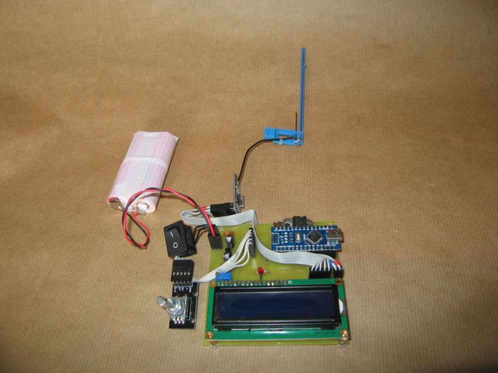
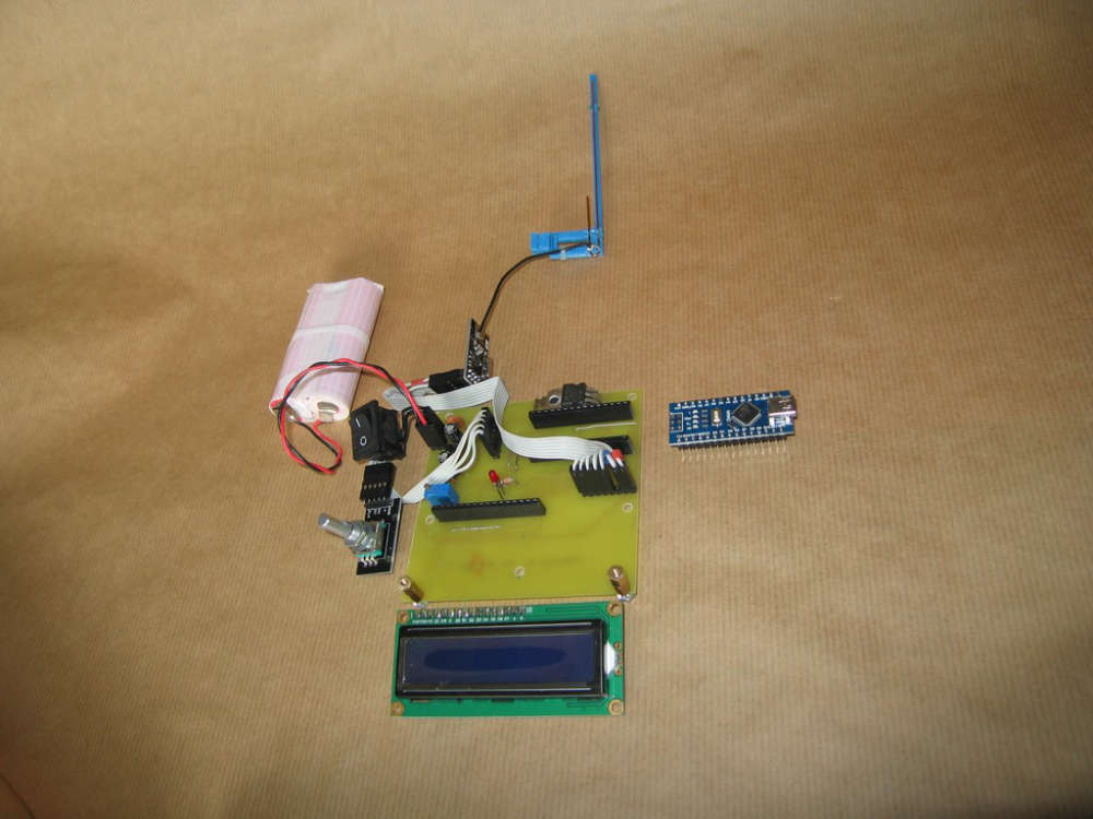
      Done ! With your great help on github, I made one nRF24DoctorNode.
      Some modifications : Battery powering with two LiIon from laptop, for 7.5 v on Arduino Nano Raw
      The 1117 of Nano out 5.0v for Nano, LCD1602 and KY040 Rotary Encoder.
      Finally the 5.0v powers a LE33 to produce 3.3v for nRF24.
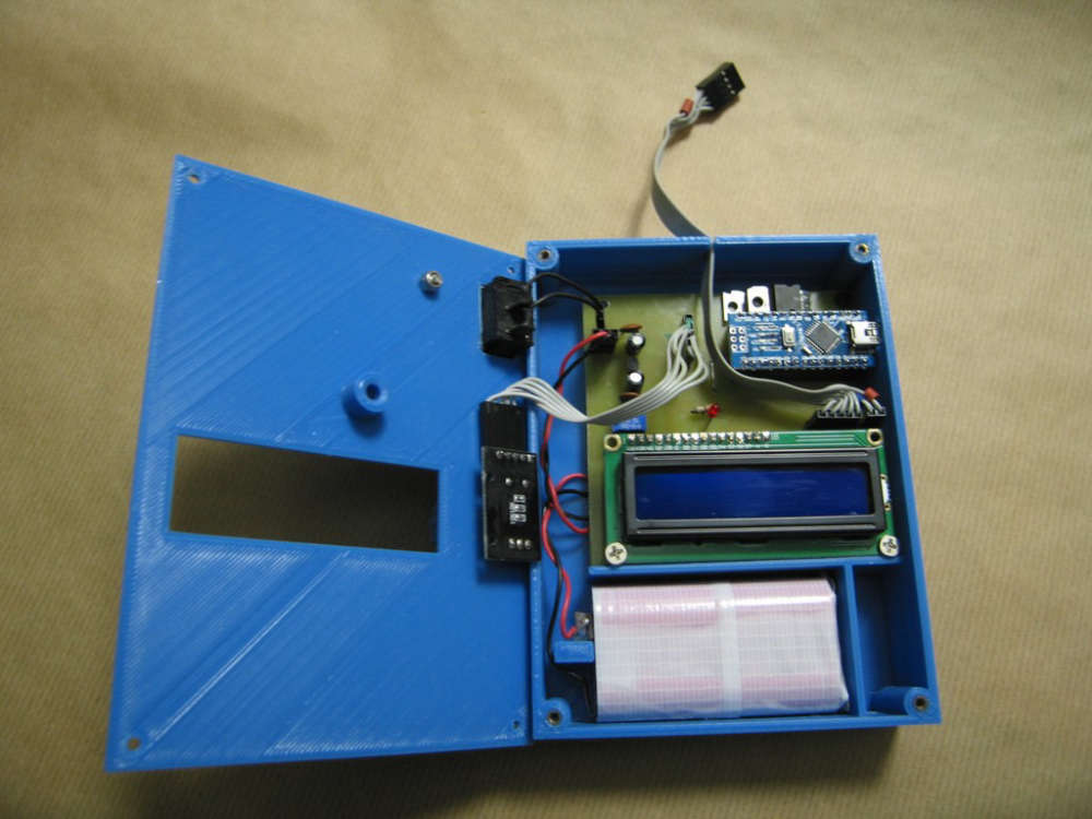
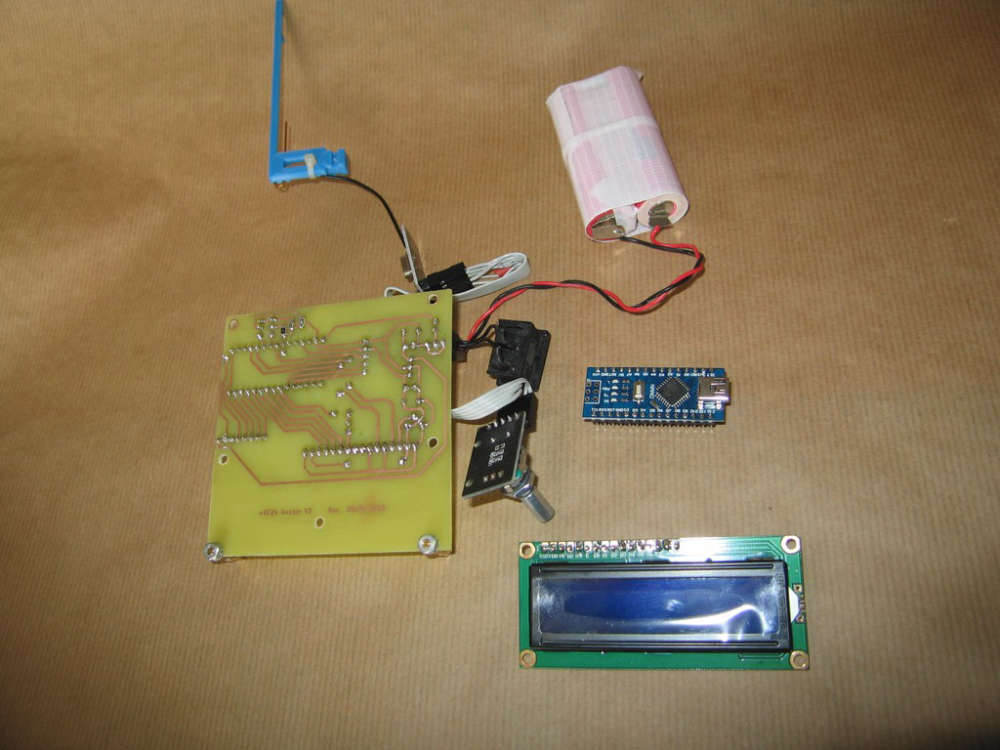
      Resistors smd, led and mosFETs (I try 40N03) are "second hand parts".
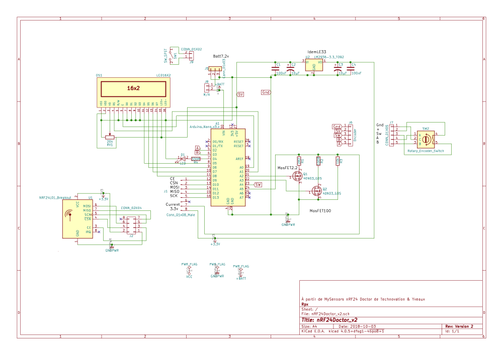
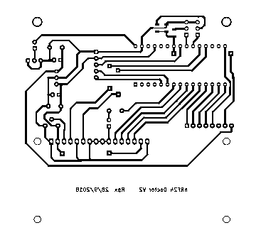
      With your PDF schematics I redraw à nRF24DoctorNode with KiKad.
      And a pcb, not so beautiful and compact than yours, but "Home made" 85x85mm single side with four straps.

      Anyway, I have one question, if the github nRF24DoctorGateway.ino compile correctly,
      the nRF24DoctorNode.ino produce one error :

      /sketchbook/nRF24DoctorNode/nRF24DoctorNode.ino: In function 'void statemachine()':
      

      nRF24DoctorNode:566: error: 'RF24_getReceivedPowerDetector' was not declared in this scope
      if (RF24_getReceivedPowerDetector())
      ^
      If I comment this line, it compile correctly.

      What's wrong ?

      Rpx

      posted in My Project
      Rpx
      Rpx
    • RE: nRF24Doctor

      @yveaux Thanks !
      Rpx.

      posted in My Project
      Rpx
      Rpx
    • RE: nRF24Doctor

      @technovation

      Very helpfull! Very good work !
      I plan to realize one.
      But I have some questions about the NODE.
      I don't understand clearly the connections of the differents parts, especialy between the MosFETs and the nRF24 Radio.
      A complete shematic with Arduino Nano, LCD, MosFETs, nRF24 Radio and power supply would be appreciated.
      I don't know the possibility, but getting the RF RX signal strenght of the NODE, will be very interesting.

      @Yveaux I am curious to see your PCB.

      Rpx.

      posted in My Project
      Rpx
      Rpx