Navigation

    • Register
    • Login
    • OpenHardware.io
    • Categories
    • Recent
    • Tags
    • Popular
    1. Home
    2. therik
    3. Best
    • Profile
    • Following
    • Followers
    • Topics
    • Posts
    • Best
    • Groups

    Best posts made by therik

    • Battery powered PIR

      This post outlines how to run a PIR sensor with 2xAA batteries and use interrupts to sleep a 3V3 8 MHz Arduino between both tripped and not-tripped states. This seems pretty straight forward, however there are a couple subtleties.

      1. The stock PIR is outfitted with a voltage regulator that requires ~4V5.
      2. Voltage ripple from the voltage booster (2xAA boost to 3V3) can cause certain sensitive sensors to reset and oscillate. Especially when entering sleep (SLEEP_MODE_PWR_DOWN), because of the large change in operating current. The reduction of the operating current, when entering sleep, will cause the booster to change frequency and magnitude of the output voltage ripple.

      Here, I will describe how I overcame this problem by modifying the PIR to work at 3V0.

      Steps:

      PIR PCB modification

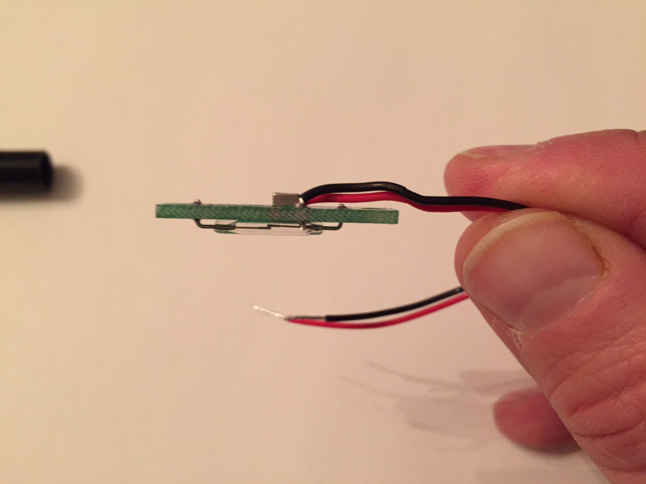
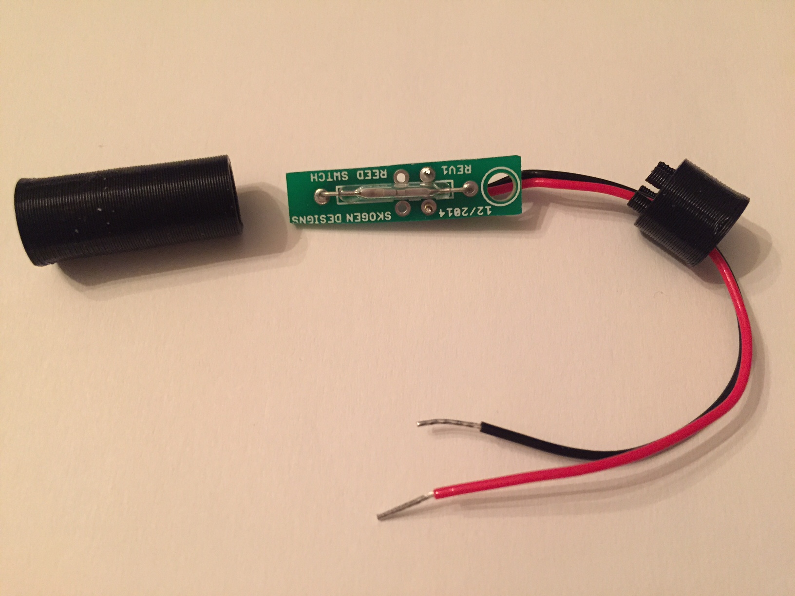
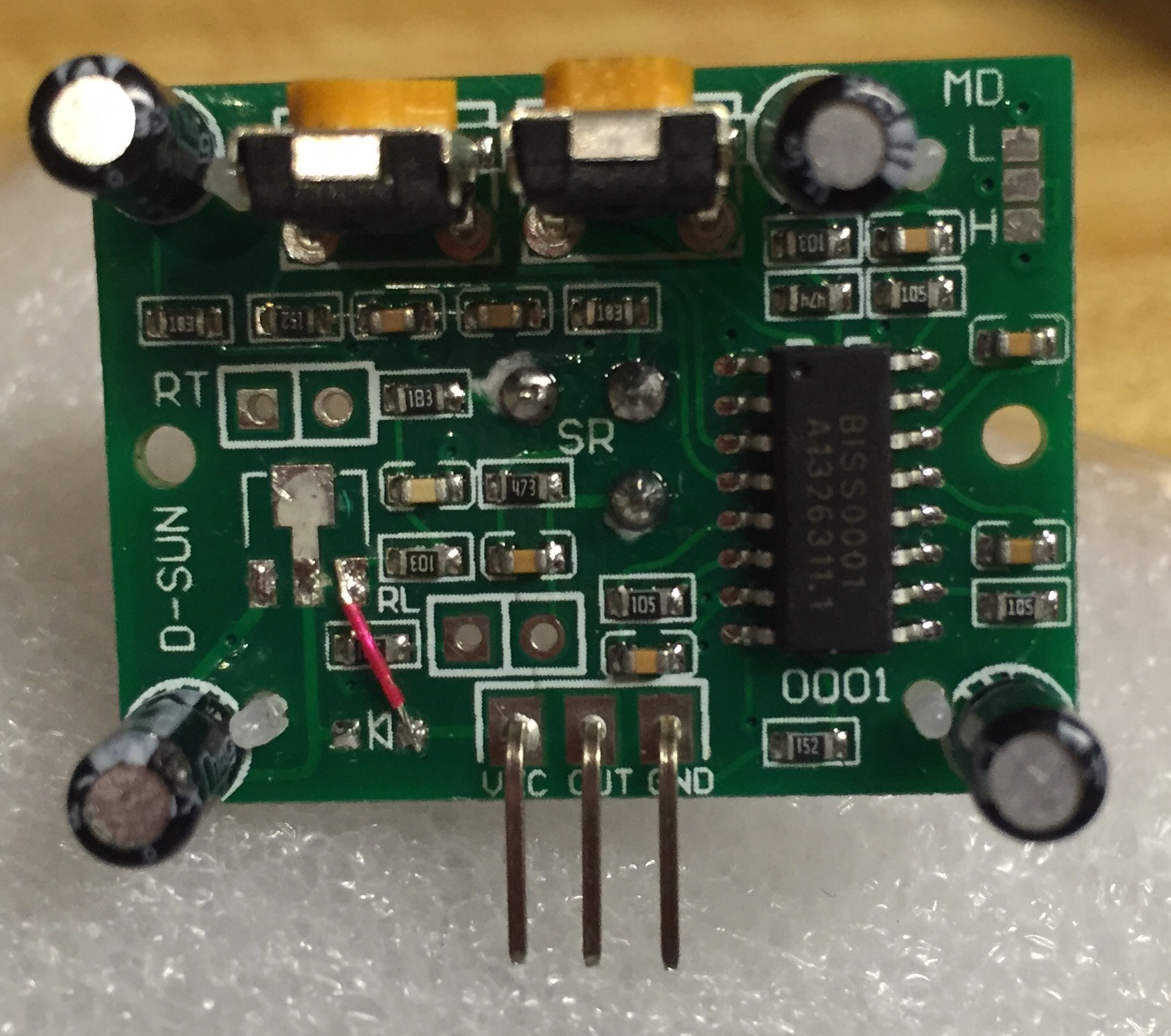
      1. Remove the voltage regulator and diode from the PIR PCB
      2. Solder a wire (red wire in the photo) from the VCC pin to the former location of the output pin of the voltage regulator

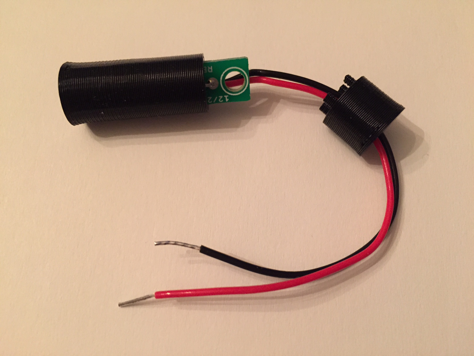
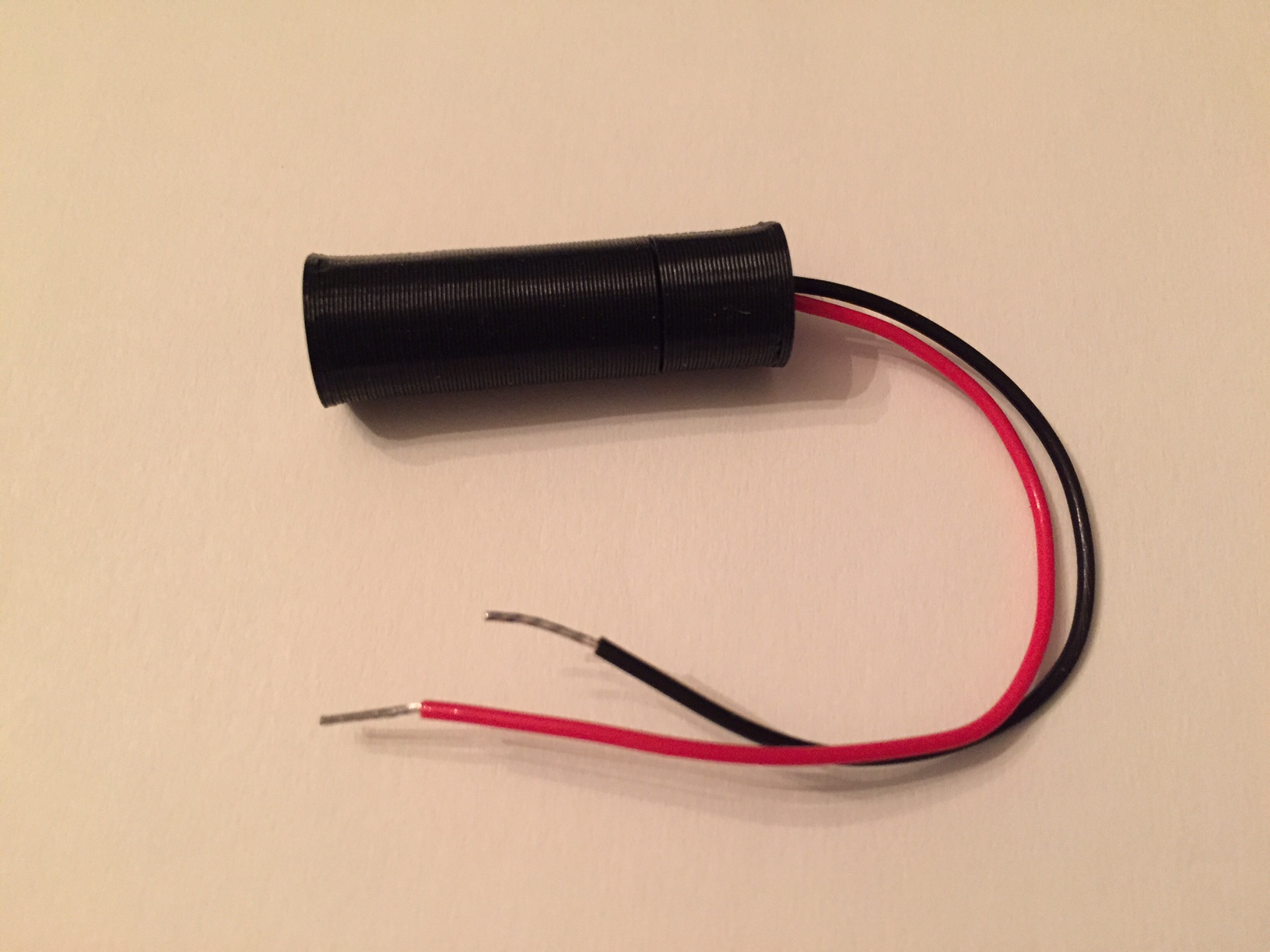
      The board should look like the photo shown below

      PIR.jpg

      Prepare the power source for the PIR

      1. The voltage from the 2xAA batteries (in my case) are boosted by a XC9140 low quiescent current 3V3 voltage regulator to power the Arduino pro mini. The radio is powered directly from the 2xAA batteries as it has its own regulator and can operate down to 1V9.
      2. The PIR sensor is based on the BISS0001 which as a supply voltage range of ~3-5 V. The modification done in earlier makes the module very sensitive to voltage ripple. In fact, the voltage ripple that occurs when switching from an awake to sleeping Arduino is enough, I believe, to cause the BISS0001 to reset and either oscillate or freeze.
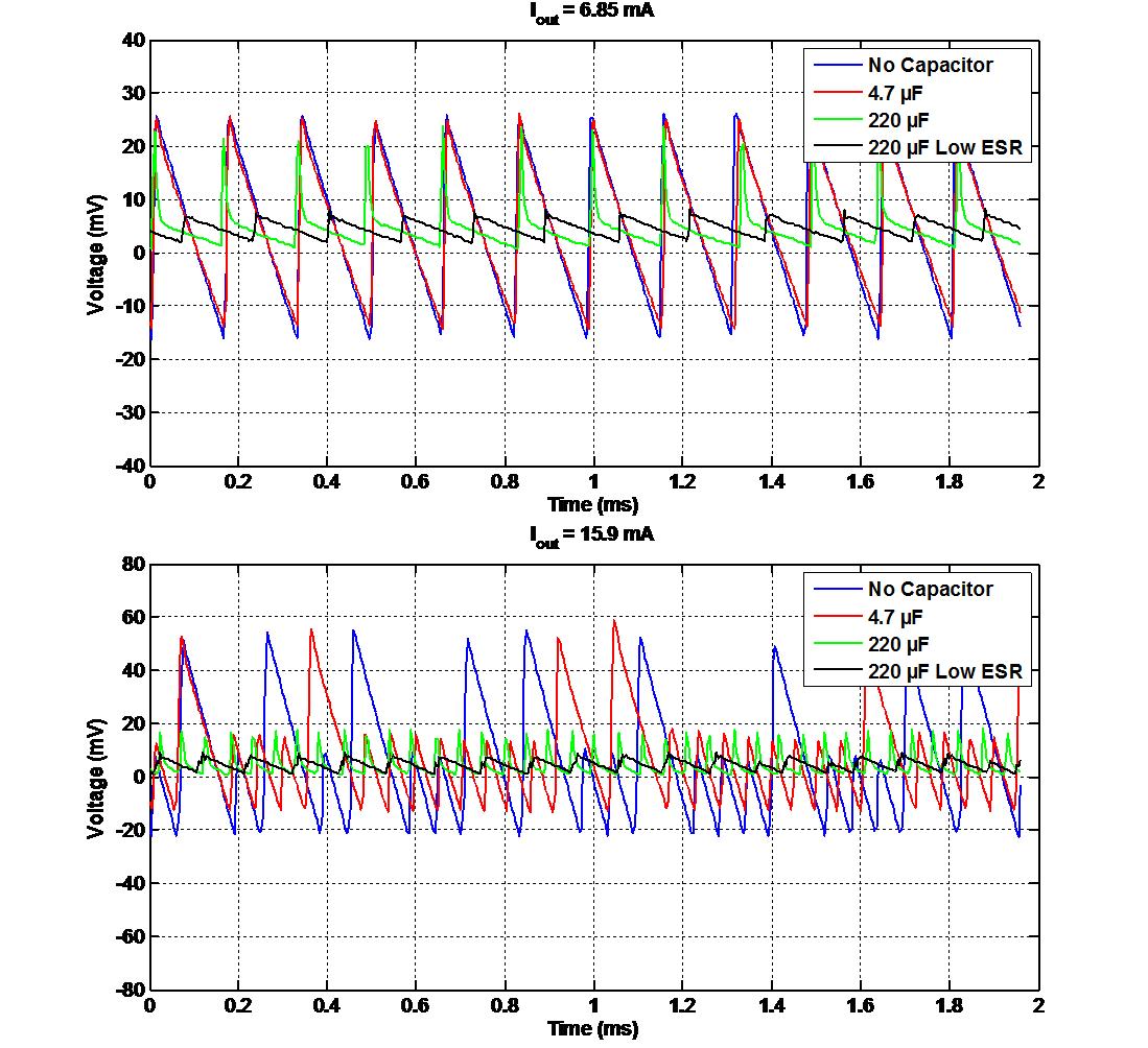
      3. I investigated a couple of solutions, but the best is to use a low-drop-out-voltage high-ripple-rejection-ratio regulator (FT531IA, 3V0, 36 µA supply current) to reduce the 3V3 boosted high-ripple supply to a steady 3V0. I know this seems silly to boost and then regulate down to another voltage but the data speaks for itself, below.

      booster_vs_LDO.png
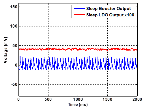
      Figure 1. Comparison of the output of the 3V3 booster and the LDO 3V0 regulator while the Arduino is sleeping. AC coupled scope termination. Note: the LDO is multiplied by 100 and offset for clarity.

      wake_up.png
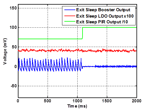
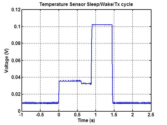
      Figure 2. Motion at around 1100 ms causes the PIR output to go high and the Arduino to wake up. Note the output from the booster quiets down and the output from the LDO is smooth. PIR and LDO outputs are offset for clarity.

      sleep.png
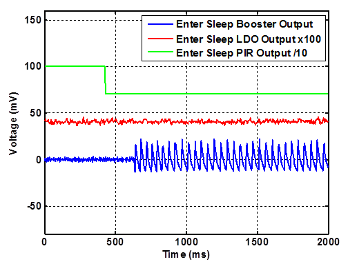
      Figure 3. Entering sleep once the PIR goes from tripped to non-tripped state. Once the Arduino starts to sleep, the output from the booster becomes noisy, while the LDO is smooth. PIR and LDO outputs are offset for clarity.

      Here is my example code (nothing fancy and much of it is borrowed from various places).

      //This program will test the PIR using interrupts 
      #include <avr/sleep.h>
      #include <avr/interrupt.h>
      
      
      void setup() 
      { 
      Serial.begin(115200);
      pinMode(3,INPUT);
      digitalWrite(3, LOW);
      pinMode(4,OUTPUT);
      //Signal PIR startup by flashing an LED 
      digitalWrite(4,HIGH);
      delay(5000);
      digitalWrite(4,LOW);
      delay(200);
      }
      
      void loop() 
      {
        //Come out of sleep and read state of PIR pin
        bool flag = digitalRead(3);
        if (flag == true)
        {
          Serial.println("tripped");
          digitalWrite(4,HIGH);
        }
        else
        {
          Serial.println("not tripped");
          digitalWrite(4,LOW);
        }
        delay(100);
        sleepNow();
      }
      
      void sleepNow()
      {
          Serial.println("Entering Sleep");
          // Set pin 3 as interrupt and attach handler:
              attachInterrupt(1, wakeUp, CHANGE);
              delay(100);
              // Choose our preferred sleep mode:
              set_sleep_mode(SLEEP_MODE_PWR_DOWN);
             
          // Set sleep enable (SE) bit:
          sleep_enable();
      
      // Put the device to sleep:
      sleep_mode();
      
      // Upon waking up, sketch continues from this point.
      sleep_disable();
      }
      
      void wakeUp(void)
      {
          detachInterrupt(1);
      }
      

      One last thing, it is necessary to attach a pull-down resistor on the PIR output pin in order to help the signal line go low when transitioning to the non-tripped state.

      posted in Hardware
      therik
      therik
    • RE: 3dprint case for motion, temp and humidity sensors with radio and batteries

      My solution was to use a low drop out voltage high ripple rejection ratio voltage regulator 3V0 to power the PIR. That special voltage regulator is fed from the booster 3V3, that keeps the voltage to the PIR rock solid. The booster is noisy especially when the arduino goes from sleep to wake and back.

      posted in My Project
      therik
      therik
    • RE: Windows GUI/Controller for MySensors

      Thank you for this excellent work. I look forward to using it in my network. I just have a couple questions regarding setting up the GUI. I've read through this thread several times, but still have a couple of gaps in my understanding.

      1. Is the gateway that interfaces with the GUI an additional gateway which listens to, and sends node messages and updates? That is, additional to one that is interfaced with the controller (in my case a serial gateway connected to a Vera controller)?

      2. If my the answer to my first question is, yes, it is an additional gateway, is the code defining the operation different such that is does not interfere with the 'true' gateway? Or is the code the same (standard serial gateway sketch) but simply does not interfere?

      3. Do the nodes require the MYSBootloader in order to show up in the 'messages' tab, or will 'messages' tab show all node traffic regardless of bootloader? Of course for over the air (OTA) sketch updates it needs the MYSBootloader.

      4. Are these the correct steps to setup operation:

      a) download and extract the files.

      'b) place the bootloader folder into /arduino/hardware path such that the MYSBootloader and the associated boards show up in the 'tools->boards' menu.

      c) connect an Arduino with the gateway sketch to a computer using a USB cable (for the serial connection).

      d) run MYSController.exe (on windows) and select the COM port of the serial gateway in the configuration.

      e) hit connect and node traffic will show up in the 'messages' tab.

      If this is correct (and now that I write it down) it seems pretty straightforward, but I didn't see it explicitly described elsewhere. Sorry to be such a beginner, and thanks for straightening me out if I'm incorrect in any step.

      posted in Controllers
      therik
      therik
    • Reed Switch normally open or normally closed

      Hi everyone,

      I'd like to show you a recently completed project. A reed switch-based sensor that can be implemented either normally open to normally closed. (I like normally open (with sense magnet) for low/no current draw, but normally closed (with sense magnet) can also be realized).

      If one does a bit of research on reed switches, it can be found that the switches can utilize two magnets for making a normally open switch (without sense magnet) a "normally closed" switch (without sense magnet).

      The idea is to drill a 7/16" hole in the jamb of a door and imbed the reed switch, then imbed a magnet into the door to complete the install. One wouldn't even know it is there; I would have a node close by to connect directly to the switch in the wall, (for me, new construction will allow this). Have a look, let me know your thoughts.

      I have designed a PCB and case (3D printed) for the switch. The PCB is straight forward, I'll leave that to anyone who'll want to replicate it, but the case took a few revs. Here is the prototype.

      image4.JPG
      Figure 1. Side view of the switch PCB. The switch is the glass tube; on the other side, I super-glued a magnet to the PCB to change the switch from normally open to "closed" (conducting). In this configuration the switch is closed (conducting), and when another magnet (sense magnet) is brought near (must be opposite polarity) the switch changes to open.

      image3.JPG
      Figure 2. Reed switch PCB and case.

      image2.JPG
      Figure 3. Reed switch fitting into case.

      image1.JPG
      Figure 4. Reed switch inside case. ready to be inserted into drilled hole in door jamb. The wires would travel to a node through a smaller hole at the end of the case. (if that makes sense). The sense magnet will be brought close to the 'top' of the cylinder when the door is closed making the switch 'open'. In this configuration, I believe a burglar would have a very hard time cutting wires that are inside a wall, so, no worries and I value normally low power (no current) operation.

      Here is the SketchUp file used to create the 3D print...you should install the "export to .STL" extension and then print away. The PCB is 1.6 mm thick. ReedSwitch_WorkingSet.skp

      Oh, and for those in the USA, I get the magnets from K&J Magnetics

      posted in Hardware
      therik
      therik
    • RE: Sensebender Gateway and Node not talking !TSM:FPAR:NO REPLY

      Reporting back.

      I previously had working a REV1 PCB of a battery powered sensor node; powering the nRF radio directly from the battery. No capacitor on the radio needed.

      I built up the REV2 of the sensor PCB which included nice things like a power switch and and a reset button, etc. Radio was powered directly from the battery just as before, but the was not receiving signals from the gateway. Put the pro-mini back on the REV1 PCB and it was working. Only difference was the switch in the path between the radio and the battery. I measured the resistance between the battery input and the radio Vcc with a 121GW multimeter.

      REV1 board (no switch): 0.03 ohm
      REV2 board (with switch): 0.5 ohm

      The switch had added a tiny bit of resistance. I shorted out the switch on the REV2 board and radio was working. I added a 10 µF cap to the radio just for good measure, also added a 220 µF polymer cap near the battery, again for good measure. and things have been stable ever since.

      Lesson learned; extra resistance in the power path can add enough voltage drop to destabilize the radio (when the radio wakes up/switches between Tx and Rx, etc). A capacitor can help with the problem. And another best practice, I believe, is to make the Vcc path as low resistance as possible.

      posted in Troubleshooting
      therik
      therik
    • RE: Efficiency of Voltage Boosters

      @a-lurker

      Yes, you got the result from the booster voltage ripple test correct, the 4.7 microF is the one recommended from the MySensors store, and the other 220 microF is a high-end audio electrolytic. The low ESR is here. Here is the data,

      Booster_Output_Ripple3.jpg

      Now, with that being said; why power the radio from the booster at all? I would submit, for battery powering a sensor node, that one should simply connect the radio directly to the battery (2xAA). The Arduino seems to be less sensitive, but still need to test. Connecting the battery directly also is more efficient, no power loss through the booster.

      My observation was, at a range of ~few feet, that I would get ~20-70% radio communication fails in the 'pingpair' sketch with the radio powered by the booster, and 100% success radio powered from 2xAA batteries, and 100% success radio powered by booster with the low ESR capacitor mentioned above. I didn't have any lower capacitor values to test (actually, I think I might have a 150 microF as well, but no lower values).

      I also tested the 5 V -to- 3 V step-down regulator from the MySensors store and that is dead flat, no voltage ripple (~1-2 mV noise). But, that is also power inefficient, however it is a good option for a plug-in node or gateway.

      posted in Hardware
      therik
      therik
    • Sleep/Wake/TXRx Cycle

      Hi guys,

      I had a chance to connect a sensor node to an oscilloscope over the last couple of days, and also to a couple of meters (Fluke and Keithley). I'd like your opinions as to the sleep/wake/TxRx cycle that is shown in the trace below.

      Cycle.jpg

      As is evident from the figure, the entire wake/TxRx cycle is around 1.44 s. I assume that the large current (measured voltage with a 10x probe across a ~5 ohm resistor) is the radio TxRx portion. And the initial current is the wake, but why it drops between is a mystery.

      Anyway, here are my numbers from the meters using an Arduino pro mini clone 3.3V running the temperature sensor sketch (1.3 library) using 2xAA through a booster ('China no LED') radio run directly from batteries.

      No modification: current from battery: 2.24 mA, current to pro-mini: 1.63 mA
      Remove LED: current form battery: 144 µA, current to pro-mini: 104 µA
      Remove LED and regulator: current from battery: 48 µA, current to pro-mini: 23 µA

      Wow, this is great, with an improved booster and 2xAA is should have a year easy.

      Thoughts?

      posted in Hardware
      therik
      therik
    • RE: HC-SR501 motion sensor

      Here is what I did...

      Removed the regulator and the diode. Jumpered from the anode of the diode to the location of the output of the 3v3 regulator. Works perfectly, and I can still utilize the original power supply pin! (good for using a standard 3 pin female header, no messy wires). Oh, and make sure your 3v3 power source is clean; boosters are notorious for having significant noise on top of the DC.

      PIR_Modified.jpg

      posted in Hardware
      therik
      therik
    • Efficiency of Voltage Boosters

      Well, I thought I would re-post the data and try to summarize the thread that was lost.

      Objective: Run a sensor node for a year on batteries. Wake period ~2 - 5 minutes.

      Approach: Use a voltage step-up converter to boost the voltage from 1 or 2 AA batteries to 3.3 V or 5 V required by the two flavors of pro-mini clones.

      Problem: Even though folks have discovered methods to put the sensor node into a deep sleep mode which draws ~100 - 200 microA; the efficiency of the step-up modules prevent realization of such a low current draw; rather, at that low current draw the efficiency of the step-up converters yields ~1-2 mA. See figures,

      PowerBooster_REV2.jpg

      The good news here is that the cost efficient step-up converters from China are just as efficient as the SparkFun NCP1402 when the LED is disabled.

      Solution: The search was on to find a more power efficient step-up converter. Here are some that I and other folks found.

      TPS61222 - These are pretty small though.
      TPS61097 - These are sort of expensive.
      XC9140AXX1 - These look promising.
      SC120 - Also cost effective, but may not be as efficient as the above.

      I have ordered the parts to construct boosters using the TPS61097-33 and XC9140A331 and will report back to the forum with the results.

      Everyone - does that summarize the original post sufficiently?

      posted in Hardware
      therik
      therik