Navigation

    • Register
    • Login
    • OpenHardware.io
    • Categories
    • Recent
    • Tags
    • Popular
    1. Home
    2. TSD
    3. Posts
    • Profile
    • Following
    • Followers
    • Topics
    • Posts
    • Best
    • Groups

    Posts made by TSD

    • RE: RFM69 ATC not working?

      @prelektr Because I wasn't making much progress, I gave up on this and added an Arduino Nano gateway that communicates with the RPi via UART. Then the ATC works. The Nano (clone) is just a $2 board, so it isn't a big deal to add it.

      posted in Troubleshooting
      TSD
      TSD
    • RE: RFM69 ATC not working?

      @gohan
      I couldn't get the RSSI measurement on the gateway to work, so I'm not doing that.

      I want to get ATC to work. As ATC uses RSSI to optimize power, a correct RSSI measurement (on the node) is needed. ATC (and so the RSSI measurement) works well on an Arduino gateway, but not on a RPi.

      As I don't have a software background and am still newish to MySensors, I'm hoping someone on the forum knows what to do. In the meantime, I'll keep digging myself 🙂

      posted in Troubleshooting
      TSD
      TSD
    • RE: RFM69 ATC not working?

      @scalz
      I found your name in the Raspberry Pi MySensor driver files. Would you happen to know why the RSSI measurement for a RPi gateway doesn't work? I'm having trouble getting ATC to work with my RPi gateway. It works well with an Arduino gateway.

      posted in Troubleshooting
      TSD
      TSD
    • RE: RFM69 ATC not working?

      @mfalkvidd
      And if you turn on ATC? Does that work? Are you on 2.3.0?

      posted in Troubleshooting
      TSD
      TSD
    • RE: RFM69 ATC not working?

      @gohan
      I just tried with the node on MySensors 2.2.0, but I get the same result. I cannot get the gateway to compile with 2.2.0, I get the following errors:

      In file included from ./MySensors.h:49:0,
                       from examples_linux/mysgw.cpp:83:
      ./drivers/RFM69/new/RFM69_new.cpp: In function ‘bool RFM69_initialise(uint32_t)’:
      ./MyConfig.h:716:26: error: ‘DEFAULT_RFM69_IRQ_NUM’ was not declared in this scope
       #define MY_RFM69_IRQ_NUM DEFAULT_RFM69_IRQ_NUM
                                ^
      ./drivers/RFM69/new/RFM69_new.cpp:230:18: note: in expansion of macro ‘MY_RFM69_IRQ_NUM’
        attachInterrupt(MY_RFM69_IRQ_NUM, RFM69_interruptHandler, RISING);
                        ^~~~~~~~~~~~~~~~
      In file included from ./MySensors.h:347:0,
                       from examples_linux/mysgw.cpp:83:
      ./hal/transport/MyTransportRFM69.cpp: In function ‘uint8_t transportReceive(void*)’:
      ./hal/transport/MyTransportRFM69.cpp:80:54: error: ‘RFM69_recv’ was not declared in this scope
        return RFM69_recv((uint8_t*)data, MAX_MESSAGE_LENGTH);
                                                            ^
      In file included from ./MySensors.h:343:0,
                       from examples_linux/mysgw.cpp:83:
      ./drivers/RFM69/new/RFM69_new.cpp: At global scope:
      ./drivers/RFM69/new/RFM69_new.cpp:749:12: warning: ‘void RFM69_encrypt(const char*)’ defined but not used [-Wunused-function]
       LOCAL void RFM69_encrypt(const char *key)
                  ^~~~~~~~~~~~~
      ./drivers/RFM69/new/RFM69_new.cpp:599:12: warning: ‘void RFM69_ATCmode(bool, int16_t)’ defined but not used [-Wunused-function]
       LOCAL void RFM69_ATCmode(const bool onOff, const int16_t targetRSSI)
                  ^~~~~~~~~~~~~
      ./drivers/RFM69/new/RFM69_new.cpp:340:15: warning: ‘uint8_t RFM69_receive(uint8_t*, uint8_t)’ defined but not used [-Wunused-function]
       LOCAL uint8_t RFM69_receive(uint8_t *buf, const uint8_t maxBufSize)


      Do you have the gateway running with 2.2.0? And ATC works for the RFM69?

      posted in Troubleshooting
      TSD
      TSD
    • RE: RFM69 ATC not working?

      @gohan @mfalkvidd
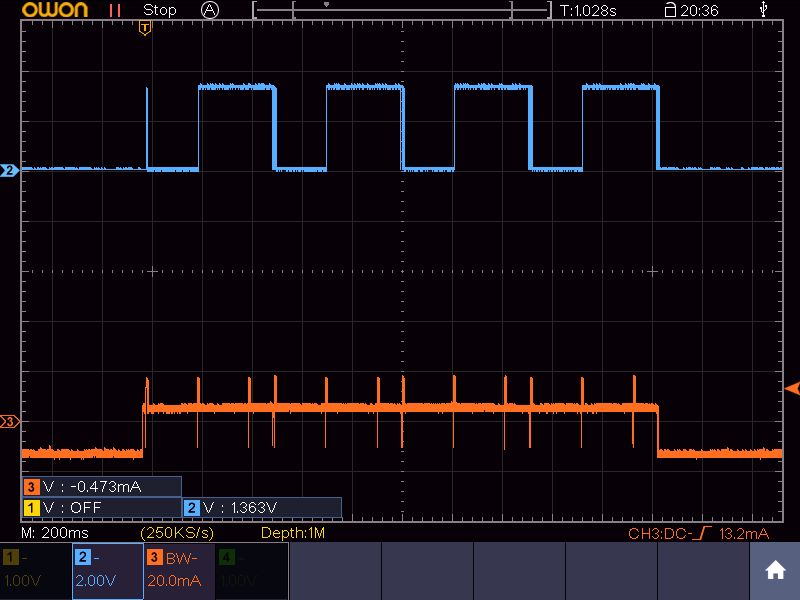
      I think it is related to the Raspberry Pi implementation of MySensors. If I use an Arduino/RFM69 gateway, the RSSI is as expected. At close range, the power drops to the minimum possible level and the RSSI is strong. I noticed that the interrupt pin is toggled during communication, see picture below (orange is node current, blue is gateway interrupt).
      0_1540320711757_arduino-gateway_node-current_gw-interrupt.bmp

      If I use the Raspberry gateway (with origin/development-3.0.0 MySensors), I get the following result (orange is node current, yellow is gateway interrupt). The same result is obtained with MySensors 2.3.0 (origin/master). I couldn't get the origin/development version to compile. It gives an error about MY_DEBUGDEVICE.
      0_1540320810723_raspberry-gateway_node-current_gw-interrupt.bmp
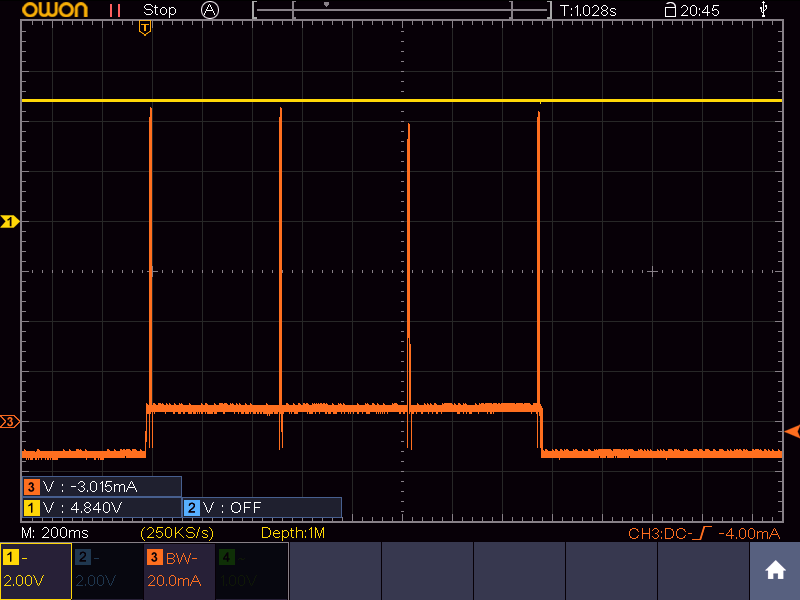
      Apart from the much higher node current (and worse RSSI), the interrupt pin is always high and not toggled.

      Are you guys using a Raspberry gateway, or an Arduino gateway?

      I haven't had time to dig into to the MySensors code further, but does any of you know if this could be the problem?

      posted in Troubleshooting
      TSD
      TSD
    • RE: RFM69 ATC not working?

      @gohan
      I added your code to my node. It gives exactly the same results as my own code. What kind of node are you using? Are you using the HW or W version of the RFM69?

      posted in Troubleshooting
      TSD
      TSD
    • RE: RFM69 ATC not working?

      @mfalkvidd
      My code now looks pretty much the same as yours, except for the OTA stuff. But I don't see gateway messages in Domoticz. The node shows up with all its measurements.

      #define MY_DEBUG_VERBOSE_GATEWAY
      #include <MySensors.h>
      
      MyMessage msgRSSI(1,V_LEVEL);
      
      #define ARDUINO 100
      // This space is intended to be used to include arduino libraries
      
      #undef ARDUINO
      
      void setup()
      {
              // Setup locally attached sensors
      }
      
      void presentation()
      {
              // Present locally attached sensors here
      present(1,S_SOUND);
      
      }
      
      void loop()
      {
              // Send locally attached sensors data here
      }
      
      void receive(const MyMessage &message)
      {
        int16_t rssiReceive = RFM69_getReceivingRSSI();
        if (message.sender == 1 ) {
          send(msgRSSI.set(rssiReceive,0));
        }
      }
      

      Is the gateway supposed to show up as a measurement? Any idea why that doesn't happen?

      posted in Troubleshooting
      TSD
      TSD
    • RE: RFM69 ATC not working?

      If I run "make install" while the code has not compiled yet, it will compile before installing. If you first run "make" seperately, "make install" will only install.

      I'm almost there. I configured an Ethernet gateway (couldn't get serial gateway to work) and can now see the temperature, receive RSSI and sending RSSI from the node in Domoticz.

      The gateway receive function shows up as "S_ARDUINO_REPEATER_NODE", but there's no data yet.

      What data should I pass on to your receive function? My gateway code is now as follows:

      #define MY_DEBUG_VERBOSE_GATEWAY
      #include <MySensors.h>
      
      
      MyMessage msgTemp(1,V_TEMP);
      MyMessage msgRSSI(2,V_LEVEL);
      
      #define ARDUINO 100
      // This space is intended to be used to include arduino libraries
      
      #undef ARDUINO
      
      void setup()
      {
              // Setup locally attached sensors
      }
      
      void presentation()
      {
              // Present locally attached sensors here
      present(2,S_SOUND);
      }
      
      void loop()
      {
              // Send locally attached sensors data here
      receive(msgTemp);
      }
      
      void receive(const MyMessage &message)
      {
        int16_t rssiReceive = RFM69_getReceivingRSSI();
        if (message.sender == 1 ) {
          send(msgRSSI.set(rssiReceive,0));
        }
      }
      
      
      posted in Troubleshooting
      TSD
      TSD
    • RE: RFM69 ATC not working?

      @mfalkvidd
      Do you mean

      #define MY_DEBUG_VERBOSE_GATEWAY
      

      That uses the GATEWAY_DEBUG("text") macro that you are referring to. I tried that, but it doesn't give any additional output in the log.

      Yes, this is the complete code I run:

      sudo ./configure --my-transport=rfm69 --my-rfm69-frequency=868 --my-is-rfm69hw --my-gateway=serial --my-serial-is-pty --my-serial-pty=/dev/ttyUSB020
      sudo make install
      sudo systemctl start mysgw.service
      

      But ttyUSB020 doesn't appear in /dev afterwards, nor does Domoticz list it.

      posted in Troubleshooting
      TSD
      TSD
    • RE: RFM69 ATC not working?

      @mfalkvidd

      #define GATEWAY_DEBUG(text)
      

      or

      #define MY_DEBUG
      

      doesn't show any additional messages in the log, besides the node messages.

      In the mean time I installed Domoticz to try it your way, but don't see the USB port that I tried to make by installing the serial gateway (ttyUSB020, which is not in /dev yet, so should be free).

      This command should take care of that, right?

      ./configure --my-gateway=serial --my-serial-is-pty --my-serial-pty=/dev/ttyUSB020
      

      Sorry to be such a pain, but I would really like to get this sorted out.

      posted in Troubleshooting
      TSD
      TSD
    • RE: RFM69 ATC not working?

      @mfalkvidd
      I was using serial gateway by the way.

      posted in Troubleshooting
      TSD
      TSD
    • RE: RFM69 ATC not working?

      @mfalkvidd
      I improved the power supply of the RFM (added linear regulator) on the gateway and the error is gone.

      The code doesn't compile if I don't declare msgTemp, as I use msgTemp in the main loop.

      Where should I see the message the GW is sending? On the node? I'm using a custom node without a serial connection, so I can't see incoming messages on the node. Is there a way to have the GW send the RSSI to its own log?

      posted in Troubleshooting
      TSD
      TSD
    • RE: RFM69 ATC not working?

      @mfalkvidd
      I modified my code to include your receive function, but I wasn't sure how to use it in the main loop.

      #include <MySensors.h>
      
      
      MyMessage msgTemp(1,V_TEMP);
      MyMessage msgRSSI(2,V_LEVEL);
      
      #define ARDUINO 100
      // This space is intended to be used to include arduino libraries
      
      #undef ARDUINO
      
      void setup()
      {
              // Setup locally attached sensors
      }
      
      void presentation()
      {
              // Present locally attached sensors here
      present(1,S_SOUND);
      
      }
      
      void loop()
      {
              // Send locally attached sensors data here
      receive(msgTemp);
      }
      
      void receive(const MyMessage &message)
      {
        int16_t rssiReceive = RFM69_getReceivingRSSI();
        if (message.sender == 1 ) {
          send(msgRSSI.set(rssiReceive,0));
        }
      }


      I figured that you have to use your receive function to capture a message from the node and then do an RSSI measurement. Since I have a msgTemp coming from the node, I used that.

      After compiling the code and running the SGW, I get the following error in the logs:

      Serial - write failed: Resource temporarily unavailable
      

      Do you know what I did wrong?

      posted in Troubleshooting
      TSD
      TSD
    • RE: RFM69 ATC not working?

      @mfalkvidd
      OK, tnx for now. I'll look at gateway rssi tomorrow evening

      posted in Troubleshooting
      TSD
      TSD
    • RE: RFM69 ATC not working?

      @mfalkvidd
      I added a sending a temperature measurement before RFM69_getReceivingRSSI and enabled ATC, but get a similar result. The code is now as follows (I cleaned up the comments):

      txPower = RFM69_getTxPowerLevel();       // Get TX power
      float temperature = readTemp705x();      // Read temperature
      
      send(msgTemp.set(temperature, 1),0);    // Send temperature
      
      rssiSend    = RFM69_getSendingRSSI();
      rssiReceive = RFM69_getReceivingRSSI();
      
      send(msgRSSI.set(txPower,2));		// Send TX power
      send(msgRSSI.set(rssiSend,3));		// Send sending RSSI
      send(msgRSSI.set(rssiReceive,3));	// Send receiving RSSI


      The gateway log shows that the power is increased until the maximum allowed (20 dBm), but no change in RSSI.

      TSF:MSG:READ,12-12-0,s=1,c=1,t=0,pt=7,l=5,sg=0:23.8
      TSF:MSG:READ,12-12-0,s=3,c=1,t=24,pt=7,l=5,sg=0:11.00
      TSF:MSG:READ,12-12-0,s=3,c=1,t=24,pt=7,l=5,sg=0:-79.000
      TSF:MSG:READ,12-12-0,s=3,c=1,t=24,pt=7,l=5,sg=0:-42.000
      
      TSF:MSG:READ,12-12-0,s=1,c=1,t=0,pt=7,l=5,sg=0:23.8
      TSF:MSG:READ,12-12-0,s=3,c=1,t=24,pt=7,l=5,sg=0:13.00
      TSF:MSG:READ,12-12-0,s=3,c=1,t=24,pt=7,l=5,sg=0:-96.000
      TSF:MSG:READ,12-12-0,s=3,c=1,t=24,pt=7,l=5,sg=0:-42.000
      
      TSF:MSG:READ,12-12-0,s=1,c=1,t=0,pt=7,l=5,sg=0:23.8
      TSF:MSG:READ,12-12-0,s=3,c=1,t=24,pt=7,l=5,sg=0:17.00
      TSF:MSG:READ,12-12-0,s=3,c=1,t=24,pt=7,l=5,sg=0:-97.000
      TSF:MSG:READ,12-12-0,s=3,c=1,t=24,pt=7,l=5,sg=0:-42.000
      
      TSF:MSG:READ,12-12-0,s=1,c=1,t=0,pt=7,l=5,sg=0:23.8
      TSF:MSG:READ,12-12-0,s=3,c=1,t=24,pt=7,l=5,sg=0:20.00
      TSF:MSG:READ,12-12-0,s=3,c=1,t=24,pt=7,l=5,sg=0:-96.000
      TSF:MSG:READ,12-12-0,s=3,c=1,t=24,pt=7,l=5,sg=0:-43.000
      

      Any idea why this doesn't work?

      I'm using a Raspberry Pi gateway now, is it easy to measure RSSI on that as well? I can switch to an Arduino gateway if required.

      posted in Troubleshooting
      TSD
      TSD
    • RE: RFM69 ATC not working?

      @mfalkvidd
      These numbers are from the node point of view.

      In the main loop, there's a piece of code that contains the RSSI measurements:

      RFM69_setTxPowerLevel(i);
      
      txPower     = RFM69_getTxPowerLevel();
      rssiReceive = RFM69_getReceivingRSSI();
      rssiSend    = RFM69_getSendingRSSI();
      
      send(msgRSSI.set(txPower,2));		// Send receiving RSSI
      send(msgRSSI.set(rssiSend,3));		// Send sending RSSI
      send(msgRSSI.set(rssiReceive,3));		// Send sending RSSI
      

      Should I use these functions differently?

      posted in Troubleshooting
      TSD
      TSD
    • RFM69 ATC not working?

      I want to use my MySensors/RFM69HW node with the lowest power possible. However, with ATC enabled, I noticed that the power is always adjusted to the maximum level possible. To investigate, I did an experiment in which I disabled ATC and increased the radio power from -2dBm to 13dBm and have the node send the receiving RSSI and sending RSSI. I recorded both the node voltage and current, as shown in the image below.

      0_1539512190978_e38431f0-03e6-44d1-82df-e9533d53cc23-image.png

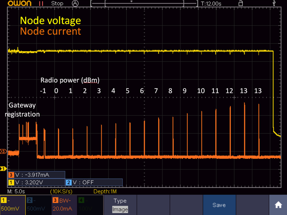
      It is clear that the radio power is linearly increased, which is good. However, the reported receiving/sending RSSIs do not change, as shown by the following gateway log (format: TX power, receiving RSSI, sending RSSI):

      TSF:MSG:READ,12-12-0,s=3,c=1,t=24,pt=7,l=5,sg=0:-2.00
      TSF:MSG:READ,12-12-0,s=3,c=1,t=24,pt=7,l=5,sg=0:-98.000
      TSF:MSG:READ,12-12-0,s=3,c=1,t=24,pt=7,l=5,sg=0:-66.000
      
      TSF:MSG:READ,12-12-0,s=3,c=1,t=24,pt=7,l=5,sg=0:-1.00
      TSF:MSG:READ,12-12-0,s=3,c=1,t=24,pt=7,l=5,sg=0:-96.000
      TSF:MSG:READ,12-12-0,s=3,c=1,t=24,pt=7,l=5,sg=0:-67.000
      
      TSF:MSG:READ,12-12-0,s=3,c=1,t=24,pt=7,l=5,sg=0:0.00
      TSF:MSG:READ,12-12-0,s=3,c=1,t=24,pt=7,l=5,sg=0:-99.000
      TSF:MSG:READ,12-12-0,s=3,c=1,t=24,pt=7,l=5,sg=0:-66.000
      
      TSF:MSG:READ,12-12-0,s=3,c=1,t=24,pt=7,l=5,sg=0:1.00
      TSF:MSG:READ,12-12-0,s=3,c=1,t=24,pt=7,l=5,sg=0:-102.000
      TSF:MSG:READ,12-12-0,s=3,c=1,t=24,pt=7,l=5,sg=0:-64.000
      
      TSF:MSG:READ,12-12-0,s=3,c=1,t=24,pt=7,l=5,sg=0:2.00
      TSF:MSG:READ,12-12-0,s=3,c=1,t=24,pt=7,l=5,sg=0:-100.000
      TSF:MSG:READ,12-12-0,s=3,c=1,t=24,pt=7,l=5,sg=0:-62.000
      
      TSF:MSG:READ,12-12-0,s=3,c=1,t=24,pt=7,l=5,sg=0:3.00
      TSF:MSG:READ,12-12-0,s=3,c=1,t=24,pt=7,l=5,sg=0:-96.000
      TSF:MSG:READ,12-12-0,s=3,c=1,t=24,pt=7,l=5,sg=0:-61.000
      
      TSF:MSG:READ,12-12-0,s=3,c=1,t=24,pt=7,l=5,sg=0:4.00
      TSF:MSG:READ,12-12-0,s=3,c=1,t=24,pt=7,l=5,sg=0:-100.000
      TSF:MSG:READ,12-12-0,s=3,c=1,t=24,pt=7,l=5,sg=0:-61.000
      
      TSF:MSG:READ,12-12-0,s=3,c=1,t=24,pt=7,l=5,sg=0:5.00
      TSF:MSG:READ,12-12-0,s=3,c=1,t=24,pt=7,l=5,sg=0:-96.000
      TSF:MSG:READ,12-12-0,s=3,c=1,t=24,pt=7,l=5,sg=0:-60.000
      
      TSF:MSG:READ,12-12-0,s=3,c=1,t=24,pt=7,l=5,sg=0:6.00
      TSF:MSG:READ,12-12-0,s=3,c=1,t=24,pt=7,l=5,sg=0:-92.000
      TSF:MSG:READ,12-12-0,s=3,c=1,t=24,pt=7,l=5,sg=0:-60.000
      
      TSF:MSG:READ,12-12-0,s=3,c=1,t=24,pt=7,l=5,sg=0:7.00
      TSF:MSG:READ,12-12-0,s=3,c=1,t=24,pt=7,l=5,sg=0:-97.000
      TSF:MSG:READ,12-12-0,s=3,c=1,t=24,pt=7,l=5,sg=0:-59.000
      
      TSF:MSG:READ,12-12-0,s=3,c=1,t=24,pt=7,l=5,sg=0:8.00
      TSF:MSG:READ,12-12-0,s=3,c=1,t=24,pt=7,l=5,sg=0:-97.000
      TSF:MSG:READ,12-12-0,s=3,c=1,t=24,pt=7,l=5,sg=0:-66.000
      
      TSF:MSG:READ,12-12-0,s=3,c=1,t=24,pt=7,l=5,sg=0:9.00
      TSF:MSG:READ,12-12-0,s=3,c=1,t=24,pt=7,l=5,sg=0:-100.000
      TSF:MSG:READ,12-12-0,s=3,c=1,t=24,pt=7,l=5,sg=0:-60.000
      
      TSF:MSG:READ,12-12-0,s=3,c=1,t=24,pt=7,l=5,sg=0:10.00
      TSF:MSG:READ,12-12-0,s=3,c=1,t=24,pt=7,l=5,sg=0:-97.000
      TSF:MSG:READ,12-12-0,s=3,c=1,t=24,pt=7,l=5,sg=0:-59.000
      
      TSF:MSG:READ,12-12-0,s=3,c=1,t=24,pt=7,l=5,sg=0:11.00
      TSF:MSG:READ,12-12-0,s=3,c=1,t=24,pt=7,l=5,sg=0:-100.000
      TSF:MSG:READ,12-12-0,s=3,c=1,t=24,pt=7,l=5,sg=0:-64.000
      
      TSF:MSG:READ,12-12-0,s=3,c=1,t=24,pt=7,l=5,sg=0:12.00
      TSF:MSG:READ,12-12-0,s=3,c=1,t=24,pt=7,l=5,sg=0:-102.000
      TSF:MSG:READ,12-12-0,s=3,c=1,t=24,pt=7,l=5,sg=0:-58.000
      
      TSF:MSG:READ,12-12-0,s=3,c=1,t=24,pt=7,l=5,sg=0:13.00
      TSF:MSG:READ,12-12-0,s=3,c=1,t=24,pt=7,l=5,sg=0:-100.000
      TSF:MSG:READ,12-12-0,s=3,c=1,t=24,pt=7,l=5,sg=0:-66.000
      

      The receiving RSSI is always about -100dBm and the sending RSSI is always around -60/-70 dBm.

      The RFM69HW has a 22uF ceramic capacitor and a 480uF elcap to decouple its power supply.

      I used MySensors 2.2.0 for this measurement, but I get the same result with 2.3.0.

      Does anyone have a clue what may be causing the RSSI to be independent of the transmit power?

      posted in Troubleshooting
      TSD
      TSD
    • RE: AC -DC transformer sourcing

      @jeremushka
      Indeed, it is a complex way to switch on a lamp, but if you only want to change the switch, I guess it's what you need to do. It would be much easier to insert something at the light bulb, as your neutral is available there.
      My French is not that good, but I think you can solve your "va et vient" by changing the NO relay in your reference schematic with a NO/NC relay (SPDT switch).

      posted in Hardware
      TSD
      TSD
    • RE: AC -DC transformer sourcing

      Hi Jeremushka,

      Are you designing your own AC/DC power supply? For low power levels (<20W), typically flyback converters are used.

      If you want to build your own flyback converter, you could use this controller IC:
      https://ac-dc.power.com/products/tinyswitch-family/tinyswitch-4/

      And this transformer: https://www.soselectronic.com/products/myrra/74010-48847

      If you're looking for a complete solution, the Aliexpress converter suggested by @poordom looks good, the 5V version can be found here and is even cheaper:
      https://www.aliexpress.com/item/5V-700mA-3-5W-AC-DC-Precision-Buck-Converter-AC-220v-to-5v-DC-step-down/32677330307.html?gps-id=pcDetailBottomMoreThisSeller&scm=1007.13339.99734.0&scm_id=1007.13339.99734.0&scm-url=1007.13339.99734.0&pvid=a8341147-314f-4c36-aec2-aa63ad557688

      It's dirt cheap, I don't have any clue about its quality. I'm sure it'll work, I just don't know about its safety level.

      posted in Hardware
      TSD
      TSD
    • RE: Timer2 does not work after including MySensors.h

      @scalz
      Your hunch was correct! When I use delay(), the current drops to 4.6mA (from >20mA). So now I can start turning off MCU peripherals to reduce the current further.

      By the way, is there good documentation to understand how all these MySensors functions work? Or do I just have to work with the Doxygen stuff and plough through all the relevant .h and .cpp files?

      posted in Troubleshooting
      TSD
      TSD
    • RE: Timer2 does not work after including MySensors.h

      @mfalkvidd Do you know anyone that might know more about this?

      posted in Troubleshooting
      TSD
      TSD
    • RE: Timer2 does not work after including MySensors.h

      @mfalkvidd @scalz
      I tried first to disable the RFM69 with the _radio.sleep() function:


      #define MY_NODE_ID 6
      #define MY_RADIO_RFM69
      #define MY_IS_RFM69HW
      #define MY_DEBUG
      #define MY_DEBUG_VERBOSE_RFM69
      
      #define LEDPIN 3
      
      #include <MySensors.h>
      
      MyMessage msgVcc(1, V_VOLTAGE);
      
      int LEDstate = 0;
      volatile byte counter = 0;
      int PostScaler = 0;
      
      ISR(TIMER2_OVF_vect) {
      	++counter;
      }
      
      void presentation()
      {
      	sendSketchInfo("Vbat", "1.0");
      	present(1, S_MULTIMETER);
      }
      
      void setup()
      {
      	// Configure timer 2
      	bitSet(ASSR,AS2);                // Select external clock for timer2
      	TCCR2B = bit(CS22) | bit(CS20);  // Set clock divider to 1024
      	bitSet(TIMSK2, TOIE2);           // Set timer 2 Overflow Interupt Enable (Timer Interupt Mask)
      	
      	// Configure LED
      	pinMode(LEDPIN,OUTPUT);
      	digitalWrite(LEDPIN,HIGH);
      }
      
      void loop()
      {
      	if (counter) {
      		counter = 0;
      		
      		// Blink LED
      		digitalWrite(LEDPIN,(LEDstate) ? HIGH : LOW);
      		LEDstate = !LEDstate;
      		
      		// Measure battery voltage and send data to gateway
      		if (PostScaler == 2) {
      			
      			_radio.receiveDone();      // Turn on radio
      			long vcc = readVcc();      // Read battery voltage
      			send(msgVcc.set(vcc, 1));  // Send battery voltage
      			_radio.sleep();            // Sleep radio
      			
      			PostScaler = 0;
      		}
      		PostScaler++;
      		sei();
      	}
      	
      	wait(2000);
      	
      }
      
      
      long readVcc() {
      	// Read 1.1V reference against AVcc
      	// set the reference to Vcc and the measurement to the internal 1.1V reference
      	#if defined(__AVR_ATmega32U4__) || defined(__AVR_ATmega1280__) || defined(__AVR_ATmega2560__)
      	ADMUX = _BV(REFS0) | _BV(MUX4) | _BV(MUX3) | _BV(MUX2) | _BV(MUX1);
      	#elif defined (__AVR_ATtiny24__) || defined(__AVR_ATtiny44__) || defined(__AVR_ATtiny84__)
      	ADMUX = _BV(MUX5) | _BV(MUX0);
      	#elif defined (__AVR_ATtiny25__) || defined(__AVR_ATtiny45__) || defined(__AVR_ATtiny85__)
      	ADMUX = _BV(MUX3) | _BV(MUX2);
      	#else
      	ADMUX = _BV(REFS0) | _BV(MUX3) | _BV(MUX2) | _BV(MUX1);
      	#endif
      
      	delay(2); // Wait for Vref to settle
      	ADCSRA |= _BV(ADSC); // Start conversion
      	while (bit_is_set(ADCSRA,ADSC)); // measuring
      
      	uint8_t low  = ADCL; // must read ADCL first - it then locks ADCH
      	uint8_t high = ADCH; // unlocks both
      
      	long result = (high<<8) | low;
      
      	result = 1125300L / result; // Calculate Vcc (in mV); 1125300 = 1.1*1023*1000
      	return result; // Vcc in millivolts
      }
      

      However, the radio doesn't turn off at all. Is there anything else that needs to be configured before this function can be used?

      posted in Troubleshooting
      TSD
      TSD
    • RE: Timer2 does not work after including MySensors.h

      @mfalkvidd, @scalz
      Thanks, now we're getting somewhere. When I use wait(), the LED blinks. That makes sense if sleep() uses power down mode, which turns off almost everything, including timer 2.

      I'll read the sensor and send the data (with MySensors) from the counter in the main loop. Then I'll see if I can get the MCU to sleep while leaving timer2 on with extended standby mode.

      Thanks for your help!

      posted in Troubleshooting
      TSD
      TSD
    • RE: Timer2 does not work after including MySensors.h

      @mfalkvidd
      I was testing without the radio even attached, to try and simplify the problem.

      But I reconnected the radio and expanded my example sketch to include a battery voltage measurement, that is transmitted to the GW with the RFM69 radio. The MySensors part of the sketch runs well, but the LED on pin 3 does not blink.

      #define MY_NODE_ID 6
      #define MY_RADIO_RFM69
      #define MY_IS_RFM69HW
      #define MY_DEBUG
      
      #define LEDPIN 3
      
      #include <MySensors.h>
      
      MyMessage msgVcc(1, V_VOLTAGE);
      
      
      int LEDstate = 0;
      volatile byte counter;
      ISR(TIMER2_OVF_vect) {
      
      	++counter;
      	if (counter == 0) {
      		digitalWrite(LEDPIN,(LEDstate) ? HIGH : LOW);
      		LEDstate = !LEDstate;
      	};
      }
      
      void presentation()
      {
      	sendSketchInfo("Vbat", "1.0");
      	present(1, S_MULTIMETER);
      
      }
      
      void setup()
      {
      	// Configure timer 2
      	bitSet(ASSR,AS2);                // Select external clock for timer2
      	TCCR2B = bit(CS22) | bit(CS20);  // Set clock divider to 1024
      	bitSet(TIMSK2, TOIE2);           // Set timer 2 Overflow Interupt Enable (Timer Interupt Mask)
      	
      	// Configure LED
      	pinMode(LEDPIN,OUTPUT);
      	digitalWrite(LEDPIN,HIGH);
      	
      	sei();
      }
      
      void loop()
      {
      	if (counter) {
      		counter = 0;
      //		digitalWrite(LEDPIN,(LEDstate) ? HIGH : LOW);
      //		LEDstate = !LEDstate;
      	}
      	
      	long vcc = readVcc();      // Read battery voltage
      	send(msgVcc.set(vcc, 1));  // Send battery voltage
      	sleep(2000);               // Sleep 2s
      
      }
      
      
      long readVcc() {
      	// Read 1.1V reference against AVcc
      	// set the reference to Vcc and the measurement to the internal 1.1V reference
      	#if defined(__AVR_ATmega32U4__) || defined(__AVR_ATmega1280__) || defined(__AVR_ATmega2560__)
      	ADMUX = _BV(REFS0) | _BV(MUX4) | _BV(MUX3) | _BV(MUX2) | _BV(MUX1);
      	#elif defined (__AVR_ATtiny24__) || defined(__AVR_ATtiny44__) || defined(__AVR_ATtiny84__)
      	ADMUX = _BV(MUX5) | _BV(MUX0);
      	#elif defined (__AVR_ATtiny25__) || defined(__AVR_ATtiny45__) || defined(__AVR_ATtiny85__)
      	ADMUX = _BV(MUX3) | _BV(MUX2);
      	#else
      	ADMUX = _BV(REFS0) | _BV(MUX3) | _BV(MUX2) | _BV(MUX1);
      	#endif
      
      	delay(2); // Wait for Vref to settle
      	ADCSRA |= _BV(ADSC); // Start conversion
      	while (bit_is_set(ADCSRA,ADSC)); // measuring
      
      	uint8_t low  = ADCL; // must read ADCL first - it then locks ADCH
      	uint8_t high = ADCH; // unlocks both
      
      	long result = (high<<8) | low;
      
      	result = 1125300L / result; // Calculate Vcc (in mV); 1125300 = 1.1*1023*1000
      	return result; // Vcc in millivolts
      }
      

      The GW log looks as expected, and repeats every 2 seconds:

      11-8-2018 11:21:18node: b9b6269f.12ee68
      msg.payload : string[73]
      "0;255;3;0;9;2046448 TSF:MSG:READ,6-6-0,s=1,c=1,t=38,pt=7,l=5,sg=0:3319.0↵"
      11-8-2018 11:21:18node: b9b6269f.12ee68
      msg.payload : string[18]
      "6;1;1;0;38;3319.0↵"
      
      11-8-2018 11:21:20node: b9b6269f.12ee68
      msg.payload : string[73]
      "0;255;3;0;9;2048732 TSF:MSG:READ,6-6-0,s=1,c=1,t=38,pt=7,l=5,sg=0:3319.0↵"
      11-8-2018 11:21:20node: b9b6269f.12ee68
      msg.payload : string[18]
      "6;1;1;0;38;3319.0↵"
      

      However, the LED that should be toggled from the ISR, doesn't blink. The LED does blink with the code that I showed at the start of this thread (without any MySensors stuff).

      My goal is to start the measurement and send the result from the ISR and not from the main loop to save more power. The current consumption during sleep is about 3.5uA now. I hope to get to around 1uA if I use timer 2. I've seen examples of people using timer 2 with the RTC, so I don't understand why this doesn't work in my case.

      Hope the issue is more clear now. Does this make any sense to you?

      posted in Troubleshooting
      TSD
      TSD
    • RE: Timer2 does not work after including MySensors.h

      @mfalkvidd

      "The application" in this case is just a blinking LED. I intend to use the ISR to read out a sensor and send the data with MySensors. But because I couldn't get the ISR to work, I reduced "the application" to an LED to keep this discussion focused on the real issue.

      Yes, it always compiles, whether I include MySensors.h or not, and whether I use Arduino IDE or Atmel Studio.

      It's just that the LED doesn't always blink. In fact, the LED only blinks if I compile with Atmel Studio and don't include MySensors.h.

      I cannot use a serial monitor, because the custom node only has an ISP interface to program the MCU, there's no USB or anything like that.

      posted in Troubleshooting
      TSD
      TSD
    • RE: Timer2 does not work after including MySensors.h

      This is the Micro Build info (excluding MySensors.h):

      Compiling 'TestSketch' for 'Arduino Nano w/ ATmega328P'
      Build Folder: "file:///C:/Users/TSD/AppData/Local/Temp/VMBuilds/TestSketch/nano_atmega328/Debug"
      Summary: Header=1 Prototypes=3 Imports=0
      Additional Defines: 
      Architecture Tools: "file:///C:/Program%20Files%20(x86)/Arduino/hardware/tools/avr/bin/"
      Api: 1.1806.1-5
      Sketch Book: "file:///C:/Users/TSD/Documents/Arduino"
      Sketch Include Paths
      Core Include Paths
      Include Path "file:///C:/Program%20Files%20(x86)/Arduino/hardware/arduino/avr/cores/arduino"
      Include Path "file:///C:/Program%20Files%20(x86)/Arduino/hardware/arduino/avr/variants/eightanaloginputs"
       
      Deep search for libraries ...
      Using previous search results: C:\Users\TSD\AppData\Local\Temp\VMBuilds\TestSketch\nano_atmega328\Debug\TestSketch.cpp
       
      Building variant ...
       
        Using previously compiled variant
       
      Building core ...
       
      Building project code ...
        Using previously compiled file: C:\Users\TSD\AppData\Local\Temp\VMBuilds\TestSketch\nano_atmega328\Debug\TestSketch.cpp.o
       
      Linking it all together ...
      # Coping cached core C:\Users\TSD\AppData\Local\Temp\VMBCore\arduino16x\1e0c139dc31076f8d2ffa4620be0d4fb\core.a to C:\Users\TSD\AppData\Local\Temp\VMBuilds\TestSketch\nano_atmega328\Debug\core.a
      
      "C:\Program Files (x86)\Arduino\hardware\tools\avr/bin/avr-gcc" -w -Os -g -flto -fuse-linker-plugin -Wl,--gc-sections -mmcu=atmega328p -o "C:\Users\TSD\AppData\Local\Temp\VMBuilds\TestSketch\nano_atmega328\Debug/TestSketch.ino.elf" "C:\Users\TSD\AppData\Local\Temp\VMBuilds\TestSketch\nano_atmega328\Debug\TestSketch.cpp.o" "C:\Users\TSD\AppData\Local\Temp\VMBuilds\TestSketch\nano_atmega328\Debug/core.a" "-LC:\Users\TSD\AppData\Local\Temp\VMBuilds\TestSketch\nano_atmega328\Debug" -lm
      ## recipe.objcopy.eep.pattern
      "C:\Program Files (x86)\Arduino\hardware\tools\avr/bin/avr-objcopy" -O ihex -j .eeprom --set-section-flags=.eeprom=alloc,load --no-change-warnings --change-section-lma .eeprom=0 "C:\Users\TSD\AppData\Local\Temp\VMBuilds\TestSketch\nano_atmega328\Debug/TestSketch.ino.elf" "C:\Users\TSD\AppData\Local\Temp\VMBuilds\TestSketch\nano_atmega328\Debug/TestSketch.ino.eep"
      ## recipe.objcopy.hex.pattern
      "C:\Program Files (x86)\Arduino\hardware\tools\avr/bin/avr-objcopy" -O ihex -R .eeprom "C:\Users\TSD\AppData\Local\Temp\VMBuilds\TestSketch\nano_atmega328\Debug/TestSketch.ino.elf" "C:\Users\TSD\AppData\Local\Temp\VMBuilds\TestSketch\nano_atmega328\Debug/TestSketch.ino.hex"
      
      Program TestSketch size: 844 bytes (used 3% of a 30.720 byte maximum) (0,97 secs)
      Minimum Memory Usage: 12 bytes (1% of a 2048 byte maximum)
       
      # Copy build result to 'Project>Property Pages>Intermediate Directory'
      # Destination: file:///C:/TestSketch/TestSketch/TestSketch/Debug
      

      There is no MySensors log, as the application does not work as soon as I include MySensors.h. The example I use here is a completely stripped version that only blinks an LED, just to show what the problem is.

      I use a custom node with an ATMEGA328PB. I use Atmel Studio 7 with Visual Micro plugin to code and AVRdude to program the hex file.

      I can blink the LED if I move the digitalWrite to the ISR (and do not include MySensors.h). I do need the counter in the loop however, because the lowest frequency of timer2 if I use a 1024 prescaler is 32768/1024=32Hz, which is too fast for my eyes to see.

      I did try to compile the code with Arduino IDE and that never works, whether I include MySensors.h or not.

      So I'm guessing there's some sort of setting or define in the Arduino software that prevents the ISR from working properly.

      Any idea what that might be?

      Thanks and regards,
      Toby

      posted in Troubleshooting
      TSD
      TSD
    • Timer2 does not work after including MySensors.h

      Hi,

      I'm trying to get timer2 to work with a 32kHz crystal. I need very low power. I've made a simple sketch that works. I use the timer2 overflow to toggle an LED on pin 3.

      However, as soon as I include MySensors.h (v2.3), the LED stops blinking. Does MySensors already use timer2? Does anyone know what's going on? Some help is much appreciated!

      Thanks and Regards,
      Toby

      
      #define MY_NODE_ID 6
      #define MY_RADIO_RFM69
      #define MY_IS_RFM69HW
      
      
      #define LEDPIN 3
      
      //#include <MySensors.h>
      
      int LEDstate = 0;
      volatile byte counter;
      
      ISR(TIMER2_OVF_vect) {
      	++counter;
      }
      
      
      void setup()
      {
      	bitSet(ASSR,AS2);                // Select external clock for timer2
      	TCCR2B = bit(CS22) | bit(CS20);  // Set clock divider to 1024
      	bitSet(TIMSK2, TOIE2);           // Set timer 2 Overflow Interupt Enable (Timer Interupt Mask)
      	pinMode(LEDPIN,OUTPUT);
      
      }
      
      void loop()
      {
      	if (counter) {
      		counter = 0;
      		digitalWrite(LEDPIN,(LEDstate) ? HIGH : LOW);
      		LEDstate = !LEDstate;
      	}
      
      }
      
      posted in Troubleshooting
      TSD
      TSD