💬 Easy/Newbie PCB (RFM69 HW/W edition) for MySensors
-
Hi @sundberg84, on Easy/Newbie PCB rfm69 version PIN3 of MysX connector is connected to 3.3V resp. to the output from voltage regulator. When I compare with Easy/Newbie PCB nrf24l01 version, MysX PIN3 is connected to input of voltage regulator (to 5V). Is this a mistake in design of Easy/PCB rfm69 version?
@ferro - Hi no - the RFM version is 3.3v only. nrf24 data pins are 5v tolerant but the rfm radio isnt so thats why.
Controller: Proxmox VM - Home Assistant
MySensors GW: Arduino Uno - W5100 Ethernet, Gw Shield Nrf24l01+ 2,4Ghz
MySensors GW: Arduino Uno - Gw Shield RFM69, 433mhz
RFLink GW - Arduino Mega + RFLink Shield, 433mhz -
@ferro - Hi no - the RFM version is 3.3v only. nrf24 data pins are 5v tolerant but the rfm radio isnt so thats why.
@sundberg84 - ok thanks, it makes sense ;). I was asking because I connected your Dimmable Led Strip daughterboard via MysX to this Easy PCB. Dimmer daughterboard is providing 5V on PIN3 (when LM2940CT voltage regulator is used on it). This would bring 5V to output of voltage regulator on Easy PCB so I disconnected PIN3 connection between dimmer daughterboard and Easy PCB. I connected PIN3 from dimmer board by wire to >3.3V power input of Easy PCB instead. Other option I'm thinking of would be not using voltage regulator on dimmer daughterboard at all but use its 12V raw voltage provided by dimmer board via MysX PIN1 (+ raw jumper on Easy PSB) and use voltage regulator (LE33) on Easy PCB only.
-
@njwyborn - you are correct, thanks for noticing! Its been corrected!
-
Hi, I've lipo battery pack with 4,2v maximum voltage (3,6v nominal). Can I safely use it with this board? Do I need any modifications?
@emdzej - I'm not sure but it's designed for 3.3v. you have to check the rfm radio for Max input voltage on VCC and io. I think it's 3.3v so you might have to regulate down your lipo battery to this.
-
-
Has anybody any experience with pcbway? I ordered via the link provided here (7 weeks ago) and only received a message from paypal. I haven't gotten a tracking number and pcbway says they can't help me without an ordernumber (which I don't have).
-
I ordered the 3rd of september (paypal mail says this: tirs. 03. sept. 2019 13:04:13 CEST (UTC+2)), are there any orders around that time?
-
Could you add a 5 pieces option? The reason is the danish customs slaps an additional "fee" of ~24eu on imports over 12eu from china.
PCBway let's you choose 5 pieces on their website.
I tried using the gerber files but before I can upload them there is a host of settings which I don't know how to set.
@kiesel - the number is set to 10 and this is nothing I can change, sorry. You can PM me about which setting you need to set and I can help you.
-
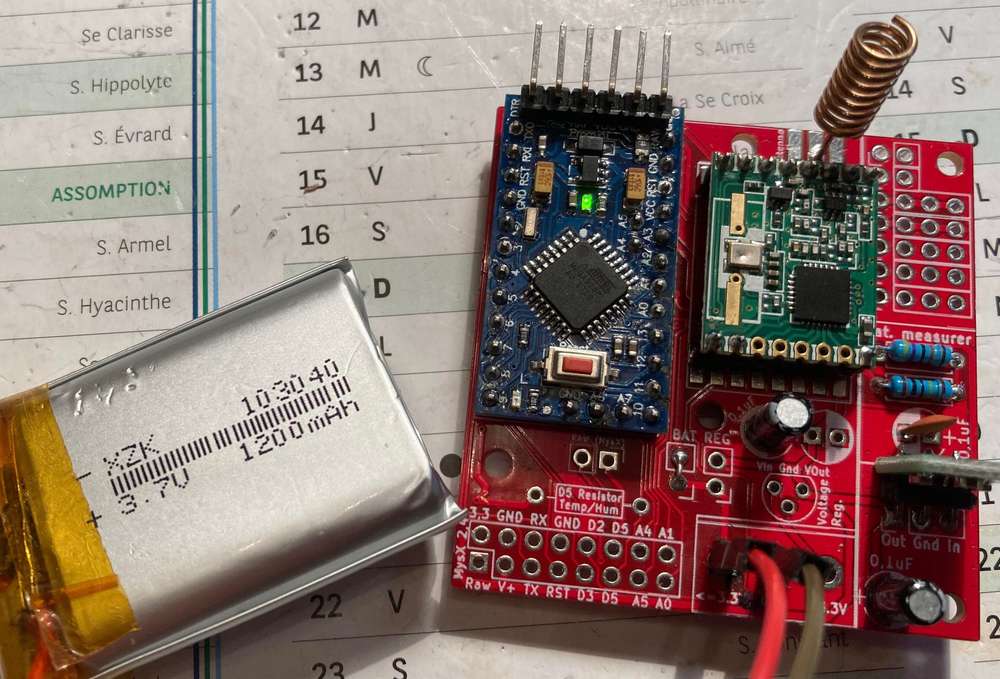
So I have made the adjustment for low power/battery mode (removed the LED, voltage regulator and sleeping most of the time).
Im having a hard time to trust my Multimeter at this point... showing 5.1uA in sleep() mode while sending shows almost 2mA! This cant be right???
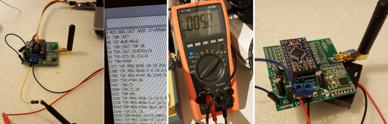
At the moment im all out of boosters... I was sure I had more so I didnt order.
What I have done now is uploaded a sketch sleeping 15min, running the vcc check (since I dont have a booster) and reporting it back to me. Lets see what happens...
@sundberg84, I know this is already an old topic, but I was sure that I did read somewhere a sleep consumption of 5µA, so I'm not completely insane :-)
I've had recently a question about this in the battery powered topic : https://forum.mysensors.org/topic/4796/battery-powered-sensors/248, because my setup with a modified pro mini (no led and no power regulator) and a connected RFM69HW only, was consuming a 133µA at sleep state.
@Yveaux pointed me to the fact that in the beginning of the site article https://www.mysensors.org/build/battery, it was mentioned that a 120µA was to be expected.So how did you get this 5µ sleep consumption?
Is it the build quality of the pro mini?
I did a test with only a pro mini and the sketch of lowpowerlab and was also measuring 133µA. -
@sundberg84, I know this is already an old topic, but I was sure that I did read somewhere a sleep consumption of 5µA, so I'm not completely insane :-)
I've had recently a question about this in the battery powered topic : https://forum.mysensors.org/topic/4796/battery-powered-sensors/248, because my setup with a modified pro mini (no led and no power regulator) and a connected RFM69HW only, was consuming a 133µA at sleep state.
@Yveaux pointed me to the fact that in the beginning of the site article https://www.mysensors.org/build/battery, it was mentioned that a 120µA was to be expected.So how did you get this 5µ sleep consumption?
Is it the build quality of the pro mini?
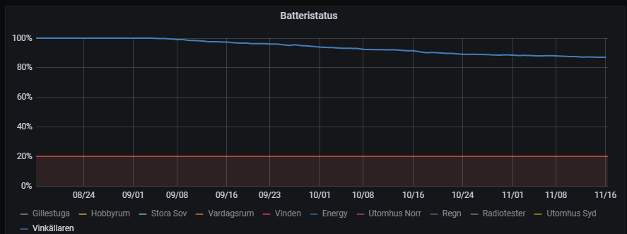
I did a test with only a pro mini and the sketch of lowpowerlab and was also measuring 133µA.@evb - Hi, to be hones I don't even remember. I dont have any exact equipment to measure except a normal multimeter, so that can be that my reading is way off, or it was without the radio? Sorry, no documentation about this and no memory at this point. But here is the battery of my EasyPCB RFM + Dallas temp sensor. I changed the batteries 3 months ago as you see and currently is about 87%.
-
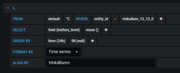
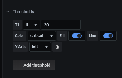
@evb - Hi, to be hones I don't even remember. I dont have any exact equipment to measure except a normal multimeter, so that can be that my reading is way off, or it was without the radio? Sorry, no documentation about this and no memory at this point. But here is the battery of my EasyPCB RFM + Dallas temp sensor. I changed the batteries 3 months ago as you see and currently is about 87%.
@sundberg84 thanks for the update.
Is the graph done with Grafana & InfluxDb? -
@sundberg84 thanks for the update.
Is the graph done with Grafana & InfluxDb? -
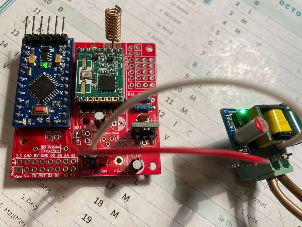
For those who use this wonderfull PCB, it is possible to use it with a regulated 5V input or with a lithium 3.7V battery :: with the following two actions:
-
as a booster use a "1.8V 3V 3.7V 5V to 3.3V Boost & Buck Low Noise Regulated Charge Pump 2 in 1 DC/DC Converter"
This will convert anything between 1.8 - 5V to 3.3V- works with regulated 5V down to 3.3V
- works with lithium battery that start at 3.7V above 3.3, and then after sometime the battery goes down less than 3.3 and is boosted to 3.3
-
connect the "BAT" jumper so that input goes through you DC/DC converter
-
-
For those who use this wonderfull PCB, it is possible to use it with a regulated 5V input or with a lithium 3.7V battery :: with the following two actions:
-
as a booster use a "1.8V 3V 3.7V 5V to 3.3V Boost & Buck Low Noise Regulated Charge Pump 2 in 1 DC/DC Converter"
This will convert anything between 1.8 - 5V to 3.3V- works with regulated 5V down to 3.3V
- works with lithium battery that start at 3.7V above 3.3, and then after sometime the battery goes down less than 3.3 and is boosted to 3.3
-
connect the "BAT" jumper so that input goes through you DC/DC converter
-
Hello! It looks like you're interested in this conversation, but you don't have an account yet.
Getting fed up of having to scroll through the same posts each visit? When you register for an account, you'll always come back to exactly where you were before, and choose to be notified of new replies (either via email, or push notification). You'll also be able to save bookmarks and upvote posts to show your appreciation to other community members.
With your input, this post could be even better 💗
Register Login