Most reliable "best" radio
-
@skywatch said in Most reliable "best" radio:
@NeverDie Maybe just ripple on the DC? Did you scope it to see? Maybe try with 10n , 100n and 470uF caps across the DC power line? - Or if there is an onboard regulator on the RF module, then maybe that gets more noisey as the voltage drop across it increases?
It does already have 100n (=0.1uF) across the DC power line, extremely near the inputs to the nRF24L01. I didn't check those other things though. However, given how widespread the use of the nRF24L01 is on this forum, if anyone happens to know whether powering it with voltage at the higher end of its range improves performance, please post. I think for the LoRa chips it doesn't matter, because they all down-convert anyway. Maybe the nRF24L01 does as well? I really hadn't expected the nRF24L01, boosted as it was with PA and LNA, to do as well as it did. So, there's that added layer of PA + LNA complexity that may have something to do with it, not just the nRF24L01 chip itself. If I was focused on just one particular chip or module, I could do those tests. But multiply that workload by six or so other radio modules, all with different idiosyncrasies, and I quickly run out of time. I may have bitten off more than I can chew. So, I just have to draw the line and either come back to it in the future or not, depending on how the global picture develops. But if someone already happens to know the answer, then hopefully they might make a posting.
This guy just recently did a video on nRF24L01 problems:
https://www.youtube.com/watch?v=Z7_Cy66Vnrcand the very first thing he talks about is long wires.
@NeverDie said in Most reliable "best" radio:
It does already have 100n (=0.1uF) across the DC power line, extremely near the inputs to the nRF24L01
Add a 10uF cap there. I found these radios are more stable with enough power to draw on during transmission.
-
@NeverDie said in Most reliable "best" radio:
Makes me wonder what those two through-holes are for near the antenna?
On ESP8266's, I wondered if the PCB antenna could be cut with a dremel tool and be fitted with an equivalent whip-wire. It would be cheap enough to try. It looks to be that the NRF24's are maybe making that easier? Again, cheap enough to try.
Thanks for all the updates to https://www.openhardware.io/user/310/projects/NeverDie#view=projects I've been busy updating all the files I've collected. You have been hard at work. All the added *.png and *jpg pictures really help. The *.rar files make it really easy to get into the guts of it all. I got KiCAD downloaded and am looking at the E28 project at the moment. Learning a new CAD tool will be a climb of its own for me.
For the benefit of others: To extract the *.rar in Windows 10, I downloaded a utility program (WinZip 21-day trial). Maybe everyone already knows that. What I have learned is that getting to the KiCAD files is a three step zip-sandwich procedure:
- download and unzip the openhardware *.zip file.
- find the *.rar file and use a utility like WinZip to unwrap it.
- unzip the resulting *.zip file.
The resulting four files (*.pcb, *.prl, *.pro, and *.sch) will deliver KiCAD access as a project via the *.pro file. It took me most of the day to learn that. There is probably an easier way.
@Larson said in Most reliable "best" radio:
To extract the *.rar in Windows 10, I downloaded a utility program (WinZip 21-day trial).
7-Zip is an open-source alternative that will do the job equally as well. https://www.7-zip.org/
-
@NeverDie said in Most reliable "best" radio:
Regarding the antenna extensions, you raise some good points. The people who posted them seem like they thought it genuinely helped, but maybe I was gullible and was wrong to post the links. If so, I'm sorry.
We are all here to share and learn and help each other out - I was only adding my thoughts on the matter for all to consider.
On the other hand, it might take only 5 minutes to try them out and see whether or not they work. A simple trial experiment would maybe settle it one way or the other pretty quickly.
Yes it would, but positioning needs to be carefully maintained to avoid false results.
@skywatch said in Most reliable "best" radio:
Thanks. What was it you were wanting me to notice about the e32 library? If it was about the FHSS, that was an e34 module in the youtube video.Oh darn it! - I got it mixed up - I am sorry for posting the wrong lib!
@skywatch said in Most reliable "best" radio:
@skywatch said in Most reliable "best" radio:
Thanks. What was it you were wanting me to notice about the e32 library? If it was about the FHSS, that was an e34 module in the youtube video.Oh darn it! - I got it mixed up - I am sorry for posting the wrong lib!
At about 3:12 in the video, he references the Lora E32 and says the pinout is the same and that "the software is compatible". I don't know if he means the library, the code (the module does the frequency hopping) or the Ebyte software for configuring the modules but it would be good to know more about it.
-
@NeverDie said in Most reliable "best" radio:
I've looked for tiny piezo's that could maybe do this, but they all seem to be different degrees of large. I know it should be possible to be tiny, becaue, for example, a digital wristwatch is able to make audible beeps. On the other hand, after looking at some teardowns, I guess digital watches uses piezo disks that are at least 1/2" in diameter. Hmmmm.... Is that really as small as it gets? Anyone here know? What about hearing aids? Surely they have something smaller. The smallest thing I've found so far has been this: https://owolff.com/page140.aspx?recordid140=534&output=pdf&delay=3000&margin=1cm which is 5mm in diameter. So, I guess forget mounting anything directly to the PCB board: wired discs are the way it's done apparently and then just tuck it somewhere inside the project enclosure.
I found these recently: https://www.cuidevices.com/micro-buzzers. Digikey seems to carry them but the smallest was listed as "0 quantity in stock" (https://www.digikey.ca/en/product-highlight/c/cui/micro-buzzers). The 4mm square version was available but of course that's just my local digikey, YMMV.
@alphaHotel said in Most reliable "best" radio:
@NeverDie said in Most reliable "best" radio:
I've looked for tiny piezo's that could maybe do this, but they all seem to be different degrees of large. I know it should be possible to be tiny, becaue, for example, a digital wristwatch is able to make audible beeps. On the other hand, after looking at some teardowns, I guess digital watches uses piezo disks that are at least 1/2" in diameter. Hmmmm.... Is that really as small as it gets? Anyone here know? What about hearing aids? Surely they have something smaller. The smallest thing I've found so far has been this: https://owolff.com/page140.aspx?recordid140=534&output=pdf&delay=3000&margin=1cm which is 5mm in diameter. So, I guess forget mounting anything directly to the PCB board: wired discs are the way it's done apparently and then just tuck it somewhere inside the project enclosure.
I found these recently: https://www.cuidevices.com/micro-buzzers. Digikey seems to carry them but the smallest was listed as "0 quantity in stock" (https://www.digikey.ca/en/product-highlight/c/cui/micro-buzzers). The 4mm square version was available but of course that's just my local digikey, YMMV.
Thanks! Looks as though mouser will be getting some in July: https://www.mouser.com/ProductDetail/CUI-Devices/CMT-322-65-SMT-TR?qs=pBJMDPsKWf2bBoY6kPbMAw%3D%3D
-
@NeverDie said in Most reliable "best" radio:
It does already have 100n (=0.1uF) across the DC power line, extremely near the inputs to the nRF24L01
Add a 10uF cap there. I found these radios are more stable with enough power to draw on during transmission.
@alphaHotel said in Most reliable "best" radio:
@NeverDie said in Most reliable "best" radio:
It does already have 100n (=0.1uF) across the DC power line, extremely near the inputs to the nRF24L01
Add a 10uF cap there. I found these radios are more stable with enough power to draw on during transmission.
Yup, already got a 10uF cap on it on the adapter board posted to openhardware.io: https://www.openhardware.io/view/22656/nRF24L01-adapter-board
-
@skywatch said in Most reliable "best" radio:
@skywatch said in Most reliable "best" radio:
Thanks. What was it you were wanting me to notice about the e32 library? If it was about the FHSS, that was an e34 module in the youtube video.Oh darn it! - I got it mixed up - I am sorry for posting the wrong lib!
At about 3:12 in the video, he references the Lora E32 and says the pinout is the same and that "the software is compatible". I don't know if he means the library, the code (the module does the frequency hopping) or the Ebyte software for configuring the modules but it would be good to know more about it.
@alphaHotel said in Most reliable "best" radio:
@skywatch said in Most reliable "best" radio:
@skywatch said in Most reliable "best" radio:
Thanks. What was it you were wanting me to notice about the e32 library? If it was about the FHSS, that was an e34 module in the youtube video.Oh darn it! - I got it mixed up - I am sorry for posting the wrong lib!
At about 3:12 in the video, he references the Lora E32 and says the pinout is the same and that "the software is compatible". I don't know if he means the library, the code (the module does the frequency hopping) or the Ebyte software for configuring the modules but it would be good to know more about it.
I think what he's saying there is that since the FHSS E34 has a built-in mcu and is operated using AT commands over UART, the comparable UART E32 module uses the same AT commands--which is about the only way I can imagine an E34 could be drop-in compatible as a replacement for the E32. These particular types of modules are advertised and sold as "wireless UARTs", and so the underlying technology is more or less transparent to that kind of solution.
-
@NeverDie said in Most reliable "best" radio:
As a result, I just now ordered some of these E01-2G4M27D
Please let us know if they arrive with or without antennas. I've been eyeing them recently but haven't pulled the trigger yet.
@alphaHotel said in Most reliable "best" radio:
E01-2G4M27D
I'm fairly certain the ones I ordered won't be arriving with antennas (as none were pictured in the aliexpress posting), but, no problem, I'll let you know for sure after they arrive. Most likely if you have an old wi-fi router that you no longer use, you could probably unscrew those antennas and use them, since they'd also be 2.4Ghz.
-
@alphaHotel said in Most reliable "best" radio:
@skywatch said in Most reliable "best" radio:
@skywatch said in Most reliable "best" radio:
Thanks. What was it you were wanting me to notice about the e32 library? If it was about the FHSS, that was an e34 module in the youtube video.Oh darn it! - I got it mixed up - I am sorry for posting the wrong lib!
At about 3:12 in the video, he references the Lora E32 and says the pinout is the same and that "the software is compatible". I don't know if he means the library, the code (the module does the frequency hopping) or the Ebyte software for configuring the modules but it would be good to know more about it.
I think what he's saying there is that since the FHSS E34 has a built-in mcu and is operated using AT commands over UART, the comparable UART E32 module uses the same AT commands--which is about the only way I can imagine an E34 could be drop-in compatible as a replacement for the E32. These particular types of modules are advertised and sold as "wireless UARTs", and so the underlying technology is more or less transparent to that kind of solution.
I think what he's saying there is that since the FHSS E34 has a built-in mcu and is operated using AT commands over UART, the comparable UART E32 module uses the same AT commands--which is about the only way I can imagine an E34 could be drop-in compatible as a replacement for the E32. These particular types of modules are advertised and sold as "wireless UARTs", and so the underlying technology is more or less transparent to that kind of solution.
Thanks for that explanation. It makes more sense now.
Yup, already got a 10uF cap on it on the adapter board posted to openhardware.io: https://www.openhardware.io/view/22656/nRF24L01-adapter-board
I saw that picture after I posted and smacked my head, of course, you did. On a related note, would it be possible to get the Kicad files for the nRF24L01 adapter board? I'd like to take a stab at building a couple of these but I want to put most of the face-down silkscreen on the face-up side too.
-
I think what he's saying there is that since the FHSS E34 has a built-in mcu and is operated using AT commands over UART, the comparable UART E32 module uses the same AT commands--which is about the only way I can imagine an E34 could be drop-in compatible as a replacement for the E32. These particular types of modules are advertised and sold as "wireless UARTs", and so the underlying technology is more or less transparent to that kind of solution.
Thanks for that explanation. It makes more sense now.
Yup, already got a 10uF cap on it on the adapter board posted to openhardware.io: https://www.openhardware.io/view/22656/nRF24L01-adapter-board
I saw that picture after I posted and smacked my head, of course, you did. On a related note, would it be possible to get the Kicad files for the nRF24L01 adapter board? I'd like to take a stab at building a couple of these but I want to put most of the face-down silkscreen on the face-up side too.
@alphaHotel said in Most reliable "best" radio:
I think what he's saying there is that since the FHSS E34 has a built-in mcu and is operated using AT commands over UART, the comparable UART E32 module uses the same AT commands--which is about the only way I can imagine an E34 could be drop-in compatible as a replacement for the E32. These particular types of modules are advertised and sold as "wireless UARTs", and so the underlying technology is more or less transparent to that kind of solution.
Thanks for that explanation. It makes more sense now.
Yup, already got a 10uF cap on it on the adapter board posted to openhardware.io: https://www.openhardware.io/view/22656/nRF24L01-adapter-board
I saw that picture after I posted and smacked my head, of course, you did. On a related note, would it be possible to get the Kicad files for the nRF24L01 adapter board? I'd like to take a stab at building a couple of these but I want to put most of the face-down silkscreen on the face-up side too.
Sure thing. I'm in the middle of something else at the moment, but I can post it later tonight.
-
I think what he's saying there is that since the FHSS E34 has a built-in mcu and is operated using AT commands over UART, the comparable UART E32 module uses the same AT commands--which is about the only way I can imagine an E34 could be drop-in compatible as a replacement for the E32. These particular types of modules are advertised and sold as "wireless UARTs", and so the underlying technology is more or less transparent to that kind of solution.
Thanks for that explanation. It makes more sense now.
Yup, already got a 10uF cap on it on the adapter board posted to openhardware.io: https://www.openhardware.io/view/22656/nRF24L01-adapter-board
I saw that picture after I posted and smacked my head, of course, you did. On a related note, would it be possible to get the Kicad files for the nRF24L01 adapter board? I'd like to take a stab at building a couple of these but I want to put most of the face-down silkscreen on the face-up side too.
@alphaHotel said in Most reliable "best" radio:
On a related note, would it be possible to get the Kicad files for the nRF24L01 adapter board?
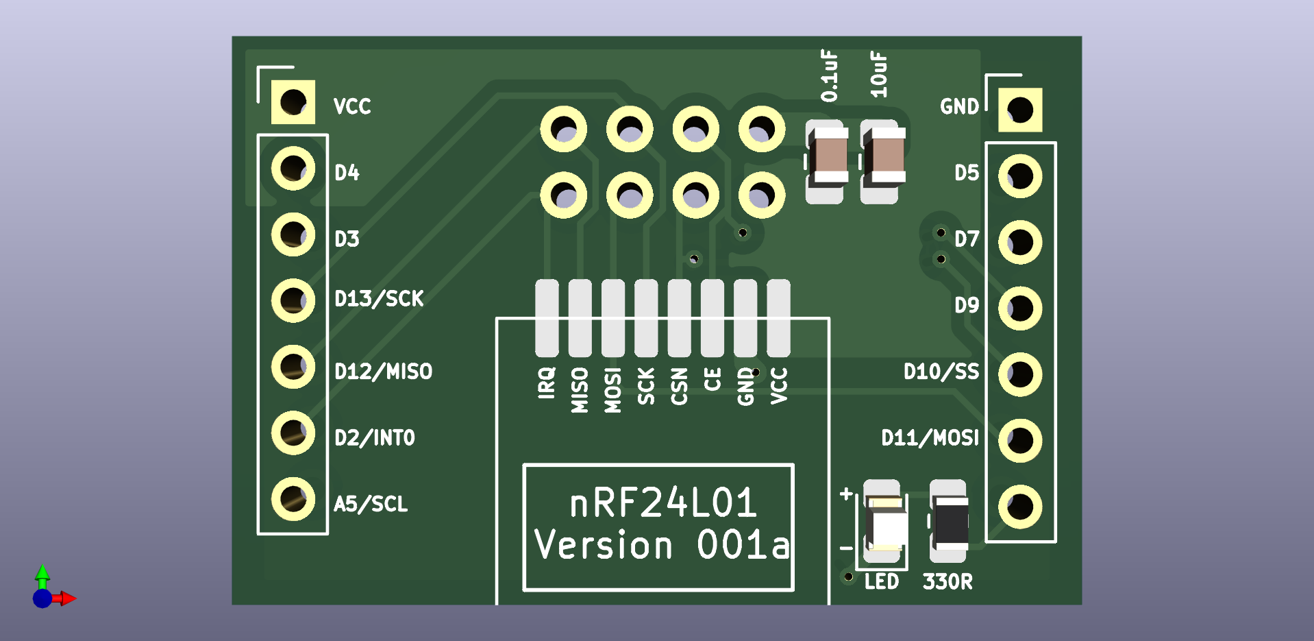
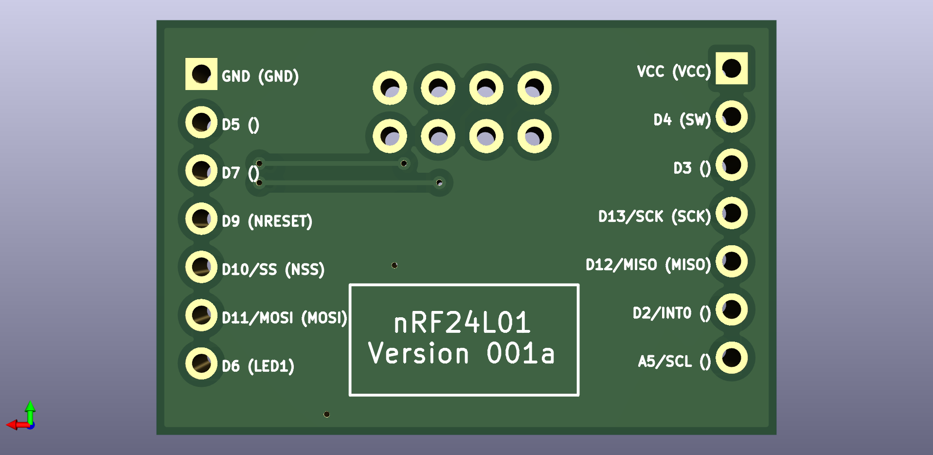
Done. Posted the .rar file to the project files. Let me know if you have any difficulty with it.
There was an error in the original: it didn't identify the IRQ pin on the backside silkscreen. I fixed that on the next (experimental) version (which is also wider), which I haven't yet received from the fab. However, the silkscreen images are here:
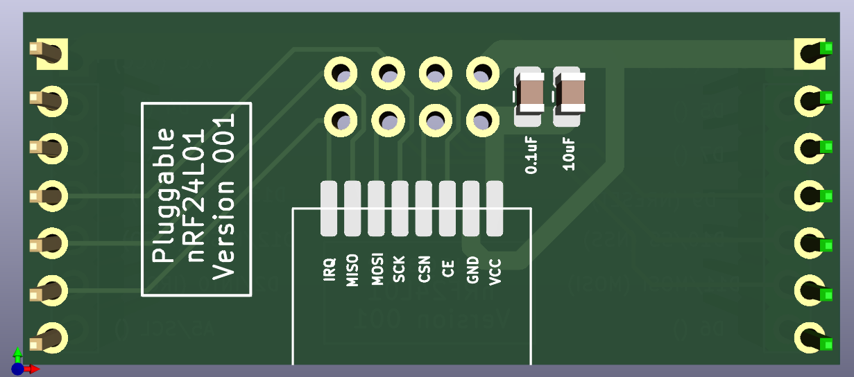
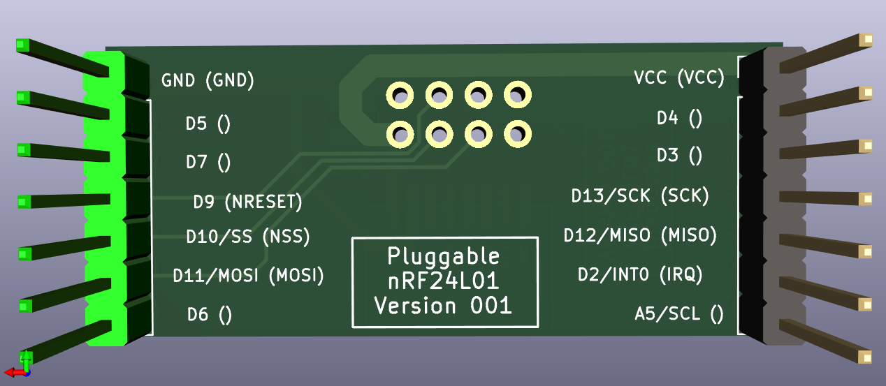
Hope that helps!
P.S. In case you're wondering, the possible next version has not only pluggable radios (as the original version had), but also pluggable MCU's, to make it easier to try different MCU's. I'm not sure yet whether or not it's a good idea, but since it's not rocket surgery I figure it is just easier to try the idea out than to overthink it.
-
@alphaHotel said in Most reliable "best" radio:
On a related note, would it be possible to get the Kicad files for the nRF24L01 adapter board?
Done. Posted the .rar file to the project files. Let me know if you have any difficulty with it.
There was an error in the original: it didn't identify the IRQ pin on the backside silkscreen. I fixed that on the next (experimental) version (which is also wider), which I haven't yet received from the fab. However, the silkscreen images are here:
Hope that helps!
P.S. In case you're wondering, the possible next version has not only pluggable radios (as the original version had), but also pluggable MCU's, to make it easier to try different MCU's. I'm not sure yet whether or not it's a good idea, but since it's not rocket surgery I figure it is just easier to try the idea out than to overthink it.
@alphaHotel Thanks for asking for the program files. I was too shy.
@NeverDie You do fine work! Thanks for the NRF24 updates to openhardware.io.
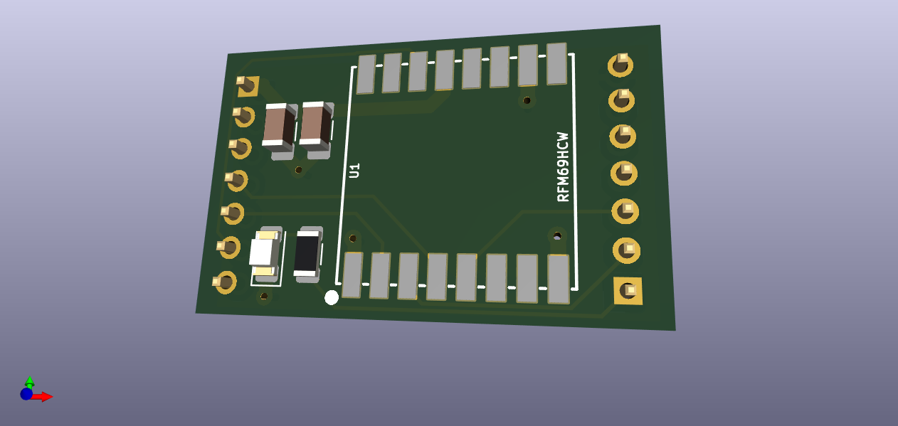
Today I placed a bundle of orders for your boards and one of mine (RFM69HCW) at OSH Park. I wanted to send you the RFM69HCW board on this forum. But, I just learned that I can't send a zip, nor sch, nor board files through MySensors. That is very smart and prudent of them. I'll do as you do and am sending the jpg files that I derived from KiCAD. You will notice my plagerism of your broad power traces and narrow signal lines. So very fine. Let me know if there is a way to share the files with you, if you are interested. I'm not ready for an openhardware.io account just yet.
-
@Larson said in Most reliable "best" radio:
@NeverDie said in Most reliable "best" radio:
It looks way cool.
Having a bit more time I watched the entire Dave Jones teardown. Very stunning review. I was feeling quite fancy after my KiCAD design but this 2015 video reminds me who I am. I am Fred Flinstone. only with Youtube. And happy enough with that!
Why go half-way? Let's light up some Winston's while we're at it. ;-) Yabba Dabba Doo!
-
@alphaHotel Thanks for asking for the program files. I was too shy.
@NeverDie You do fine work! Thanks for the NRF24 updates to openhardware.io.
Today I placed a bundle of orders for your boards and one of mine (RFM69HCW) at OSH Park. I wanted to send you the RFM69HCW board on this forum. But, I just learned that I can't send a zip, nor sch, nor board files through MySensors. That is very smart and prudent of them. I'll do as you do and am sending the jpg files that I derived from KiCAD. You will notice my plagerism of your broad power traces and narrow signal lines. So very fine. Let me know if there is a way to share the files with you, if you are interested. I'm not ready for an openhardware.io account just yet.
@Larson Congrats on finishing your first KiCAD PCB. Once you're over that hump, it just keeps getting easier.
I don't think there's any harm to posting to openhardware.io. It's' pretty well designed so that people who just want to buy stuff can look at finished projects and not be bothered by work in progress. To the extent you can eventually finish a project, then it helps mysensors. As for me, I think I'm pretty much done with RFM69, but maybe someone else would be interested.
-
This is what I came up with for a platform that has both pluggable MCU's and pluggable radios:
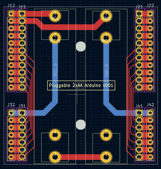
It's a bit wider than the previous test platform to give enough space between both the two AA batteries themselves and between those batteries and the pin headers. It also has a separate row of pins along the outside in case you want to have any shields that go on top. I did away with the switch entirely. Now if you want to power it off, you just remove a battery. So, doing all that renders the backplane/power-source very simple. Also, I included two mounting holes so that the whole thing can be mounted inside a project box. Yesterday I ordered this PCB along with a pluggable atmega328p MCU board and a pluggable radio board from a fab, so nothing physical to show-and-tell just yet.
-
@alphaHotel said in Most reliable "best" radio:
On a related note, would it be possible to get the Kicad files for the nRF24L01 adapter board?
Done. Posted the .rar file to the project files. Let me know if you have any difficulty with it.
There was an error in the original: it didn't identify the IRQ pin on the backside silkscreen. I fixed that on the next (experimental) version (which is also wider), which I haven't yet received from the fab. However, the silkscreen images are here:
Hope that helps!
P.S. In case you're wondering, the possible next version has not only pluggable radios (as the original version had), but also pluggable MCU's, to make it easier to try different MCU's. I'm not sure yet whether or not it's a good idea, but since it's not rocket surgery I figure it is just easier to try the idea out than to overthink it.
@NeverDie said in Most reliable "best" radio:
Done. Posted the .rar file to the project files. Let me know if you have any difficulty with it.
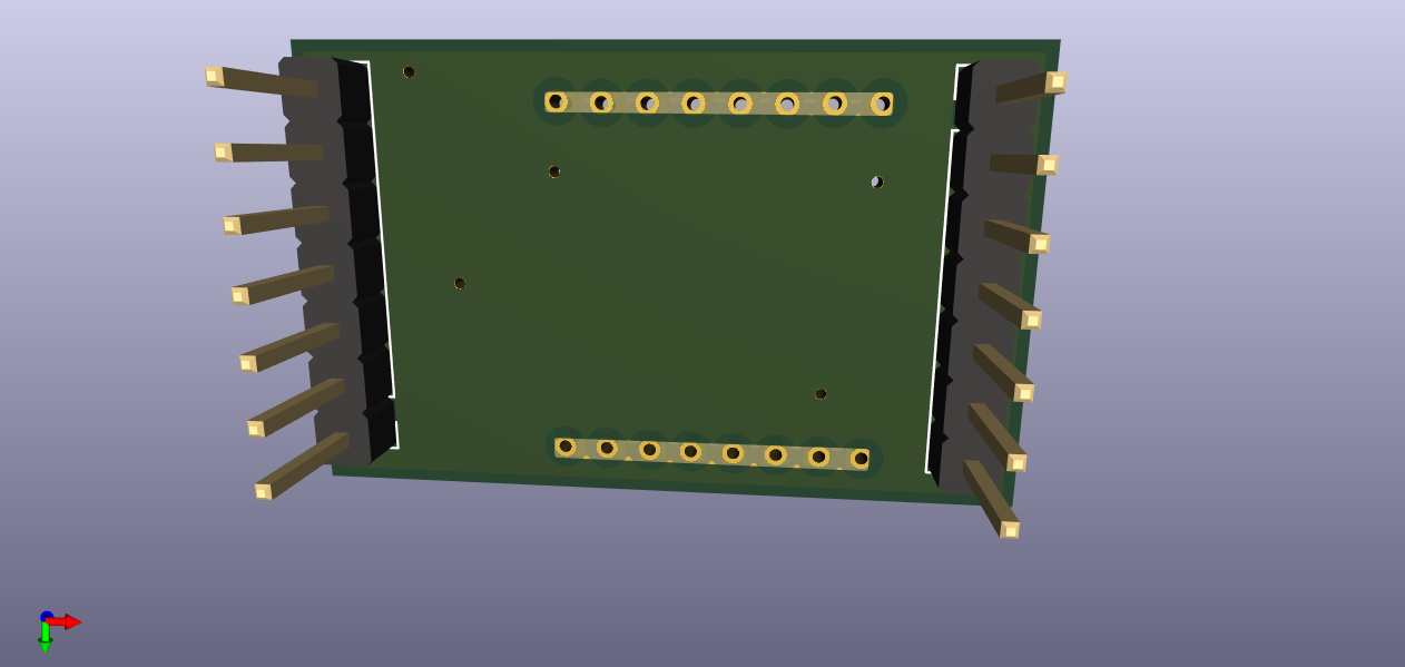
Thank you. I didn't have any issues with the files though it did warn that the footprints for the radio modules are in
MyGlobalLibrary, which I don't have. See the screenshot below. If they could be put into a library within the project, it would be more portable than it already is but I was able to work with it as is.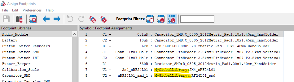
I made a few mods including adding a ground plane and I'll try to get a repo on GitHub up and running for it tonight after work. With a new version in the works, perhaps I'll hold off getting some of these boards fabricated. In the interim, here's a view of my 3D model.
P.S. In case you're wondering, the possible next version has not only pluggable radios (as the original version had), but also pluggable MCU's, to make it easier to try different MCU's. I'm not sure yet whether or not it's a good idea, but since it's not rocket surgery I figure it is just easier to try the idea out than to overthink it.
At one point in this thread, I marvelled at the battery shield and wondered about having it separated from the MCU. Just conditioned power on the first shield then MCU, then radio. The complexity of it though is beyond my current level as I don't have as much experience with alternative MCU's (though I've been thinking we need to start looking at something with more program memory, like the ATmega4808/9). On the other hand, it should be just a matter of defining what needs to be passed from shield to shield (layer to layer?). Power, ground, SPI signals, perhaps I2C signals and a few other GPIO signals. Please do though consider lining up the pins such that they would also fit a breadboard layout.
-
This is what I came up with for a platform that has both pluggable MCU's and pluggable radios:
It's a bit wider than the previous test platform to give enough space between both the two AA batteries themselves and between those batteries and the pin headers. It also has a separate row of pins along the outside in case you want to have any shields that go on top. I did away with the switch entirely. Now if you want to power it off, you just remove a battery. So, doing all that renders the backplane/power-source very simple. Also, I included two mounting holes so that the whole thing can be mounted inside a project box. Yesterday I ordered this PCB along with a pluggable atmega328p MCU board and a pluggable radio board from a fab, so nothing physical to show-and-tell just yet.
@NeverDie With the first version of the battery/MCU board, you lamented running traces directly under the batteries. You have the space now to re-route them but choose not to. Did you find a way to resolve the issue it caused?
-
@NeverDie With the first version of the battery/MCU board, you lamented running traces directly under the batteries. You have the space now to re-route them but choose not to. Did you find a way to resolve the issue it caused?
@alphaHotel said in Most reliable "best" radio:
@NeverDie With the first version of the battery/MCU board, you lamented running traces directly under the batteries. You have the space now to re-route them but choose not to. Did you find a way to resolve the issue it caused?
Actually, I fixed it on the new version (pictured above). The red traces run on top, so they're adequately isolated from the battery holder metal, which is on the back side except for the through-holes where it sticks through the board. Where I ran into trouble was running traces on the back side, beneath the battery holder metal. If the battery holder metal was pressed up hard against the board, some shorts resulted on some of the boards. The workaround was to not press the battery holder metal hard up against the board, but the new version removes that concern entirely.
-
@NeverDie said in Most reliable "best" radio:
Done. Posted the .rar file to the project files. Let me know if you have any difficulty with it.
Thank you. I didn't have any issues with the files though it did warn that the footprints for the radio modules are in
MyGlobalLibrary, which I don't have. See the screenshot below. If they could be put into a library within the project, it would be more portable than it already is but I was able to work with it as is.I made a few mods including adding a ground plane and I'll try to get a repo on GitHub up and running for it tonight after work. With a new version in the works, perhaps I'll hold off getting some of these boards fabricated. In the interim, here's a view of my 3D model.
P.S. In case you're wondering, the possible next version has not only pluggable radios (as the original version had), but also pluggable MCU's, to make it easier to try different MCU's. I'm not sure yet whether or not it's a good idea, but since it's not rocket surgery I figure it is just easier to try the idea out than to overthink it.
At one point in this thread, I marvelled at the battery shield and wondered about having it separated from the MCU. Just conditioned power on the first shield then MCU, then radio. The complexity of it though is beyond my current level as I don't have as much experience with alternative MCU's (though I've been thinking we need to start looking at something with more program memory, like the ATmega4808/9). On the other hand, it should be just a matter of defining what needs to be passed from shield to shield (layer to layer?). Power, ground, SPI signals, perhaps I2C signals and a few other GPIO signals. Please do though consider lining up the pins such that they would also fit a breadboard layout.
@alphaHotel said in Most reliable "best" radio:
On the other hand, it should be just a matter of defining what needs to be passed from shield to shield (layer to layer?). Power, ground, SPI signals, perhaps I2C signals and a few other GPIO signals.
Yup, you got it. That's all there is to it. Power, ground, SPI, chip enable, chip select, maybe RX/TX enable (on some radios), and enough interrupt pins to take advantage of whatever interrupt or DIO pins the radio has to offer up. Looking back on it, I probably should have kept A5 off of the radio module, since that's used by I2C, and used some other pin instead. So... it's still a work in progress, but getting better.
-
@NeverDie said in Most reliable "best" radio:
Done. Posted the .rar file to the project files. Let me know if you have any difficulty with it.
Thank you. I didn't have any issues with the files though it did warn that the footprints for the radio modules are in
MyGlobalLibrary, which I don't have. See the screenshot below. If they could be put into a library within the project, it would be more portable than it already is but I was able to work with it as is.I made a few mods including adding a ground plane and I'll try to get a repo on GitHub up and running for it tonight after work. With a new version in the works, perhaps I'll hold off getting some of these boards fabricated. In the interim, here's a view of my 3D model.
P.S. In case you're wondering, the possible next version has not only pluggable radios (as the original version had), but also pluggable MCU's, to make it easier to try different MCU's. I'm not sure yet whether or not it's a good idea, but since it's not rocket surgery I figure it is just easier to try the idea out than to overthink it.
At one point in this thread, I marvelled at the battery shield and wondered about having it separated from the MCU. Just conditioned power on the first shield then MCU, then radio. The complexity of it though is beyond my current level as I don't have as much experience with alternative MCU's (though I've been thinking we need to start looking at something with more program memory, like the ATmega4808/9). On the other hand, it should be just a matter of defining what needs to be passed from shield to shield (layer to layer?). Power, ground, SPI signals, perhaps I2C signals and a few other GPIO signals. Please do though consider lining up the pins such that they would also fit a breadboard layout.
@alphaHotel said in Most reliable "best" radio:
I didn't have any issues with the files though it did warn that the footprints for the radio modules are in MyGlobalLibrary, which I don't have. See the screenshot below. If they could be put into a library within the project, it would be more portable than it already is but I was able to work with it as is.
Thanks for the feedback. I really would like it to be both portable and standalone, so I'll look into setting up a standalone library to include into the .rar that will make for a better KiCAD 6 project archive.
-
@alphaHotel said in Most reliable "best" radio:
@NeverDie With the first version of the battery/MCU board, you lamented running traces directly under the batteries. You have the space now to re-route them but choose not to. Did you find a way to resolve the issue it caused?
Actually, I fixed it on the new version (pictured above). The red traces run on top, so they're adequately isolated from the battery holder metal, which is on the back side except for the through-holes where it sticks through the board. Where I ran into trouble was running traces on the back side, beneath the battery holder metal. If the battery holder metal was pressed up hard against the board, some shorts resulted on some of the boards. The workaround was to not press the battery holder metal hard up against the board, but the new version removes that concern entirely.
@NeverDie said in Most reliable "best" radio:
@alphaHotel said in Most reliable "best" radio:
@NeverDie With the first version of the battery/MCU board, you lamented running traces directly under the batteries. You have the space now to re-route them but choose not to. Did you find a way to resolve the issue it caused?
Actually, I fixed it on the new version (pictured above). The red traces run on top, so they're adequately isolated from the battery holder metal, which is on the back side except for the through-holes where it sticks through the board. Where I ran into trouble was running traces on the back side, beneath the battery holder metal. If the battery holder metal was pressed up hard against the board, some shorts resulted on some of the boards. The workaround was to not press the battery holder metal hard up against the board, but the new version removes that concern entirely.
Okay, I see now. I misunderstood the original issue and also didn't think about the top/bottom side orientation in relation to those traces vis-a-vis the battery holders. Thanks for clarifying.
Hello! It looks like you're interested in this conversation, but you don't have an account yet.
Getting fed up of having to scroll through the same posts each visit? When you register for an account, you'll always come back to exactly where you were before, and choose to be notified of new replies (either via email, or push notification). You'll also be able to save bookmarks and upvote posts to show your appreciation to other community members.
With your input, this post could be even better 💗
Register Login