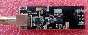
nRF24L01+PA+LNA
-
Knows anyone someone who use this module with power amplifier ??
Rf module nRF24L01+PA+LNA . I test it .. but still have same distance like module with no PA .. and searching way to obtain why .. and if is it possible ..
I use antenna .. standard antenna from WiFi router.. gateway is powered from USB .. use 3.3V regulator .. and very big capacitor on power pin for RF module. if measure 3.3V deviation in Tx mode then have less than 13mV .. and I don't think that 13mV is big .. ..I test it with small sensor with led and buzzer .. if lost signal then give me signal.. also use nRF24L01+PA+LNA module with big capacitor .. but power from 2xAA battery .. total 3V .. and I don't think so this is problem..in all is used MySensors firmware with ATmega328p , internal 8Mhz RC oscilator..
how to test it .. how to check what is problem .. if test module with PCB antenna then have same distance.. and it's not normal.. if module with PA just add 1 or 2db then must have more then 10% longer distance ..
IF I test module CC1101 with maximum +12db output power (868Mhz) then have very nice distance .. I know 2.4Ghz is different like 868Mhz .. But I test in free space.. not in building..
best regards..
your's idea ??
-
Take a look here https://www.youtube.com/watch?v=lR60toEjHl8
-
Knows anyone someone who use this module with power amplifier ??
Rf module nRF24L01+PA+LNA . I test it .. but still have same distance like module with no PA .. and searching way to obtain why .. and if is it possible ..
I use antenna .. standard antenna from WiFi router.. gateway is powered from USB .. use 3.3V regulator .. and very big capacitor on power pin for RF module. if measure 3.3V deviation in Tx mode then have less than 13mV .. and I don't think that 13mV is big .. ..I test it with small sensor with led and buzzer .. if lost signal then give me signal.. also use nRF24L01+PA+LNA module with big capacitor .. but power from 2xAA battery .. total 3V .. and I don't think so this is problem..in all is used MySensors firmware with ATmega328p , internal 8Mhz RC oscilator..
how to test it .. how to check what is problem .. if test module with PCB antenna then have same distance.. and it's not normal.. if module with PA just add 1 or 2db then must have more then 10% longer distance ..
IF I test module CC1101 with maximum +12db output power (868Mhz) then have very nice distance .. I know 2.4Ghz is different like 868Mhz .. But I test in free space.. not in building..
best regards..
your's idea ??
@dzairo Did you try to adjust the power settings in "MyConfig.h"? I increased the range by lowering the power to "RF24_PA_LOW' = 12dBm.
ifndef MyConfig_h #define MyConfig_h /*** * Configure Sensor Network */ #define RF24_CHANNEL 76 //RF channel for the sensor net, 0-127 #define RF24_DATARATE RF24_250KBPS //RF24_250KBPS for 250kbs, RF24_1MBPS for 1Mbps, or RF24_2MBPS for 2Mbps #define RF24_PA_LEVEL RF24_PA_LOW //Sensor PA Level == RF24_PA_MIN=-18dBm, RF24_PA_LOW=-12dBm, RF24_PA_HIGH=-6dBM, and RF24_PA_MAX=0dBm #define RF24_PA_LEVEL_GW RF24_PA_LOW //Gateway PA Level, defaults to Sensor net PA Level. Tune here if using an amplified nRF2401+ in your gateway. #define BASE_RADIO_ID ((uint64_t)0xA8A8E1FC00LL) // This is also act as base value for sensor nodeId addresses. Change this (or channel) if you have more than one sensor network. // MySensors online examples defaults #define DEFAULT_CE_PIN 9 #define DEFAULT_CS_PIN 10 /*** * Enable/Disable debug logging */ #define DEBUG #endif -
Hi. Right now I tested with this setting:
#ifndef MyConfig_h
#define MyConfig_h

/***
 * Configure Sensor Network
 */
#define RF24_CHANNEL	   76             //RF channel for the sensor net, 0-127
#define RF24_DATARATE 	   RF24_250KBPS   //RF24_250KBPS for 250kbs, RF24_1MBPS for 1Mbps, or RF24_2MBPS for 2Mbps
#define RF24_PA_LEVEL 	   RF24_PA_MAX    //Sensor PA Level == RF24_PA_MIN=-18dBm, RF24_PA_LOW=-12dBm, RF24_PA_HIGH=-6dBM, and RF24_PA_MAX=0dBm
#define RF24_PA_LEVEL_GW   RF24_PA_MAX  //Gateway PA Level, defaults to Sensor net PA Level.  Tune here if using an amplified nRF2401+ in your gateway.
#define BASE_RADIO_ID 	   ((uint64_t)0xA8A8E1FC00LL) // This is also act as base value for sensor nodeId addresses. Change this (or channel) if you have more than one sensor network.

// MySensors online examples defaults
#define DEFAULT_CE_PIN 9
#define DEFAULT_CS_PIN 10


/***
 * Enable/Disable debug logging
 */
#define DEBUG

#endif
what do you mean .. I must set lower power output ??? write more .. if set lower power in standard module (no PA or LNA) .. then maximum is +0db and distance is around 30m , but I use in gateway and in sensor madule what contacin external power amplifer .. +20db (MCP01 IC) .. and standard antenna.. .. write more .. what module you use ..??? send photo is you have..
best regards..
-
Hi. Right now I tested with this setting:
#ifndef MyConfig_h
#define MyConfig_h

/***
 * Configure Sensor Network
 */
#define RF24_CHANNEL	   76             //RF channel for the sensor net, 0-127
#define RF24_DATARATE 	   RF24_250KBPS   //RF24_250KBPS for 250kbs, RF24_1MBPS for 1Mbps, or RF24_2MBPS for 2Mbps
#define RF24_PA_LEVEL 	   RF24_PA_MAX    //Sensor PA Level == RF24_PA_MIN=-18dBm, RF24_PA_LOW=-12dBm, RF24_PA_HIGH=-6dBM, and RF24_PA_MAX=0dBm
#define RF24_PA_LEVEL_GW   RF24_PA_MAX  //Gateway PA Level, defaults to Sensor net PA Level.  Tune here if using an amplified nRF2401+ in your gateway.
#define BASE_RADIO_ID 	   ((uint64_t)0xA8A8E1FC00LL) // This is also act as base value for sensor nodeId addresses. Change this (or channel) if you have more than one sensor network.

// MySensors online examples defaults
#define DEFAULT_CE_PIN 9
#define DEFAULT_CS_PIN 10


/***
 * Enable/Disable debug logging
 */
#define DEBUG

#endif
what do you mean .. I must set lower power output ??? write more .. if set lower power in standard module (no PA or LNA) .. then maximum is +0db and distance is around 30m , but I use in gateway and in sensor madule what contacin external power amplifer .. +20db (MCP01 IC) .. and standard antenna.. .. write more .. what module you use ..??? send photo is you have..
best regards..
@dzairo I feel we are repeating your discussion which took place a 4 months ago... . I am using kind of standard modules from ebay
It just happens that they don't perform very well under high power settings. When set to Medium or Low. performance is much better. The best performance I have is when attach them to a separate power supply with > 100 uF & 100nF ceramic capacitors added in parallel to the power lines (directly on the connector). These boards (store) happen to work pretty well as a power supply..
Mostly trial and error. I need to cross several brick walls.....
-
I try it .. right now .. thanks ..
15:36 - I tested .. yes working for longer distance.. suppper... now I try it in free area..
17:20 - I tested it with battery operated module.
Receiver : 3xAA convert to 3.3V ,
MCU : ATmega328p , internal 8Mhz RC oscilator as gateway ,
RF module : nRF24L01+ , -12dB output powre , 256kbps ,
This RF module
no external PA+LNA , antenna is standard antenna from WiFi router , I not use antenna what comming with RF module.Transmiter : 2xAA
MCU : ATmega328p , internal 8Mhz RC oscilator as sensor , send every 1 sec data .. and waiting for ACK , if receive ACK then generate buzzer short beep , if no ACK then generate 2x long beep sound .
RF module : nRF24L01+ , -12dB , 250kbps with external PA+LNA ( MCP01)I test it .. and got up to 600m range . .in free area ..
exist similar chip .. and is possible replace with nRF24L01 : look at this : RF2400
best regards.
-
Hello,
I use 2" nRF24L01+ with PA + LNA " bought on ebay.
I connected the arduino directly to the nRF including 3.3V.
I feel the distance very very short. Maybe 4 meters with a Wall... Should I define RF24_PA_LEVEL_GW to max" ?:
#define RF24_PA_LEVEL_GW RF24_PA_MAX ???
Can I expect something better ?
Or should I use a specific 3.3V power supply which is not very convenient ?
rgdsthanks
-
@doblanch the 3.3V output from an arduino can not provide the current needed for the PA-LNA module.
Add a seperate power source and/or use a lower setting for your sensor PA level (RF24_PA_LEVEL)" in the MyConfig.h@korttoma OK. Thank you. Should I use an external power source for both GW + node ? If ext power use, I can keep the level set to max ? In fact, what is the best way to get a maximum range ? Also, should I connect a capacitor ? thank you by advance. rgds
-
@doblanch the 3.3V output from an arduino can not provide the current needed for the PA-LNA module.
Add a seperate power source and/or use a lower setting for your sensor PA level (RF24_PA_LEVEL)" in the MyConfig.h@korttoma In the arduino doc, it's 40ma for 3.3V pin
http://arduino.cc/en/main/arduinoBoardUno
I read in the nrf24L01 doc 11.3ma;
Transmitter
x00 Programmable output power: 0, -6, -12 or -18dBm x00 11.3mA at 0dBm output power
• Receiver
x00 Fast AGC for improved dynamic range x00 Integrated channel filters
x00 13.5mA at 2MbpsSo it should be enough no ? Did I miss something ?
-
Thos figures are for the module without the PA LNA. The PA LNA version draws over 100mA
-
@korttoma mmm... that's pretty much clear from now. we are then close to the limit then...which kind of power module is recommended ?
This one sounds good ? :: http://www.ebay.com/itm/1Pcs-New-3-3V-5V-MB102-Breadboard-Power-Supply-Module-For-Arduino-Breadboard/281372556250?_trksid=p2047675.c100005.m1851&_trkparms=aid%3D222007%26algo%3DSIC.MBE%26ao%3D1%26asc%3D29266%26meid%3D1f59438fd24b4f9eb809f216f307ad1a%26pid%3D100005%26rk%3D5%26rkt%3D6%26sd%3D181718046489&rt=nc&autorefresh=trueit allows to use with one 5V input, and Two output, one is 3.3V and the second one 5V.... do you have a better idea ? thanks in advance rgds.
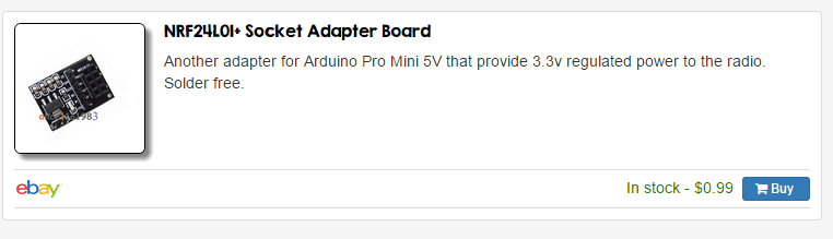
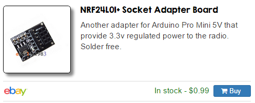
@doblanch Take a look at MySensors store. The adapter board works good with the amplified radio.
-
@doblanch Take a look at MySensors store. The adapter board works good with the amplified radio.
@AWI I confused from now. This adapter allow to convert 5V to 3.3V. HOwever my problem right now is a problem of consumption. It seems that NRF+PA consummes 100+Ma... each I/O pin on arduino is max 50Ma... I wil not solve my problem to put a 5V to 3.3V ? I need to add a new power source able to provide more than 100ma or more ? correct ?
-
@AWI I confused from now. This adapter allow to convert 5V to 3.3V. HOwever my problem right now is a problem of consumption. It seems that NRF+PA consummes 100+Ma... each I/O pin on arduino is max 50Ma... I wil not solve my problem to put a 5V to 3.3V ? I need to add a new power source able to provide more than 100ma or more ? correct ?
@doblanch Sorry for confusing you. If you are using the Uno the 5V pin can deliver about 450mA if powered from USB and 650mA if powered from power jack. This is more than enough to supply the "Socket Adapter Board" which has a powerfull regulator. The 3.3V pin on the Uno can only supply 40mA.
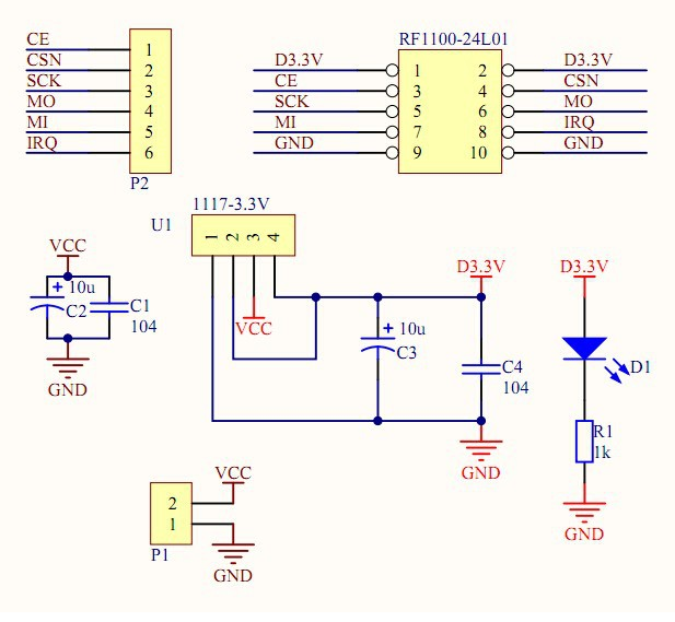
There is nothing wrong with the supply you mentioned either. The converter board is more convenient to connect and includes the capacitors (ceramic & tantalum) needed for a stable supply . Schematic below:
-
@AWI I confused from now. This adapter allow to convert 5V to 3.3V. HOwever my problem right now is a problem of consumption. It seems that NRF+PA consummes 100+Ma... each I/O pin on arduino is max 50Ma... I wil not solve my problem to put a 5V to 3.3V ? I need to add a new power source able to provide more than 100ma or more ? correct ?
@doblanch ehm.. ATmega chip can get around 25mA maximum from one pin .. but nRF24L01 + PA + LNA is not powered from arduino pin .. is powered from converter.. and this converter must give more then 800mA then .. not problem power .. and if you power Arduino from 5V then OK .. nRF24L01+ have pin 5V tolerant inputs ..
-
@dzairo The "tolerance" you mention is only for in/outputs not for the power supply. It will most likely burn when you supply it with 5V
Hello! It looks like you're interested in this conversation, but you don't have an account yet.
Getting fed up of having to scroll through the same posts each visit? When you register for an account, you'll always come back to exactly where you were before, and choose to be notified of new replies (either via email, or push notification). You'll also be able to save bookmarks and upvote posts to show your appreciation to other community members.
With your input, this post could be even better 💗
Register Login