nRF24L01+PA+LNA
-
@doblanch the 3.3V output from an arduino can not provide the current needed for the PA-LNA module.
Add a seperate power source and/or use a lower setting for your sensor PA level (RF24_PA_LEVEL)" in the MyConfig.h@korttoma OK. Thank you. Should I use an external power source for both GW + node ? If ext power use, I can keep the level set to max ? In fact, what is the best way to get a maximum range ? Also, should I connect a capacitor ? thank you by advance. rgds
-
@doblanch the 3.3V output from an arduino can not provide the current needed for the PA-LNA module.
Add a seperate power source and/or use a lower setting for your sensor PA level (RF24_PA_LEVEL)" in the MyConfig.h@korttoma In the arduino doc, it's 40ma for 3.3V pin
http://arduino.cc/en/main/arduinoBoardUno
I read in the nrf24L01 doc 11.3ma;
Transmitter
x00 Programmable output power: 0, -6, -12 or -18dBm x00 11.3mA at 0dBm output power
• Receiver
x00 Fast AGC for improved dynamic range x00 Integrated channel filters
x00 13.5mA at 2MbpsSo it should be enough no ? Did I miss something ?
-
Thos figures are for the module without the PA LNA. The PA LNA version draws over 100mA
-
@korttoma mmm... that's pretty much clear from now. we are then close to the limit then...which kind of power module is recommended ?
This one sounds good ? :: http://www.ebay.com/itm/1Pcs-New-3-3V-5V-MB102-Breadboard-Power-Supply-Module-For-Arduino-Breadboard/281372556250?_trksid=p2047675.c100005.m1851&_trkparms=aid%3D222007%26algo%3DSIC.MBE%26ao%3D1%26asc%3D29266%26meid%3D1f59438fd24b4f9eb809f216f307ad1a%26pid%3D100005%26rk%3D5%26rkt%3D6%26sd%3D181718046489&rt=nc&autorefresh=trueit allows to use with one 5V input, and Two output, one is 3.3V and the second one 5V.... do you have a better idea ? thanks in advance rgds.
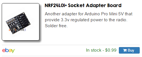
@doblanch Take a look at MySensors store. The adapter board works good with the amplified radio.
-
@doblanch Take a look at MySensors store. The adapter board works good with the amplified radio.
@AWI I confused from now. This adapter allow to convert 5V to 3.3V. HOwever my problem right now is a problem of consumption. It seems that NRF+PA consummes 100+Ma... each I/O pin on arduino is max 50Ma... I wil not solve my problem to put a 5V to 3.3V ? I need to add a new power source able to provide more than 100ma or more ? correct ?
-
@AWI I confused from now. This adapter allow to convert 5V to 3.3V. HOwever my problem right now is a problem of consumption. It seems that NRF+PA consummes 100+Ma... each I/O pin on arduino is max 50Ma... I wil not solve my problem to put a 5V to 3.3V ? I need to add a new power source able to provide more than 100ma or more ? correct ?
@doblanch Sorry for confusing you. If you are using the Uno the 5V pin can deliver about 450mA if powered from USB and 650mA if powered from power jack. This is more than enough to supply the "Socket Adapter Board" which has a powerfull regulator. The 3.3V pin on the Uno can only supply 40mA.
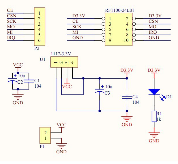
There is nothing wrong with the supply you mentioned either. The converter board is more convenient to connect and includes the capacitors (ceramic & tantalum) needed for a stable supply . Schematic below:
-
@AWI I confused from now. This adapter allow to convert 5V to 3.3V. HOwever my problem right now is a problem of consumption. It seems that NRF+PA consummes 100+Ma... each I/O pin on arduino is max 50Ma... I wil not solve my problem to put a 5V to 3.3V ? I need to add a new power source able to provide more than 100ma or more ? correct ?
@doblanch ehm.. ATmega chip can get around 25mA maximum from one pin .. but nRF24L01 + PA + LNA is not powered from arduino pin .. is powered from converter.. and this converter must give more then 800mA then .. not problem power .. and if you power Arduino from 5V then OK .. nRF24L01+ have pin 5V tolerant inputs ..
-
@dzairo The "tolerance" you mention is only for in/outputs not for the power supply. It will most likely burn when you supply it with 5V
-
@doblanch Sorry for confusing you. If you are using the Uno the 5V pin can deliver about 450mA if powered from USB and 650mA if powered from power jack. This is more than enough to supply the "Socket Adapter Board" which has a powerfull regulator. The 3.3V pin on the Uno can only supply 40mA.
There is nothing wrong with the supply you mentioned either. The converter board is more convenient to connect and includes the capacitors (ceramic & tantalum) needed for a stable supply . Schematic below:
@AWI That's clear then.... I didn't know that 5V on uno can draw 450ma... ON their website, they precise only I/O and 3.3V... From now it's very clear. I will use the 5V pin, with "something" to reduce it to 3.3V...
I have this in stock : http://www.ebay.com/itm/Mini-3A-DC-DC-Converter-Adjustable-Step-down-Power-Supply-Module-replace-LM2596s-/261328784505?ssPageName=ADME:L:OU:FR:3160
a power down module, IN="5V" OUT-"adjustable (including 3.3V)"
Do you know for the nano the +5V max draw ?
Thank for your help, grandly appreciated. -
@doblanch The Nano has an 78M05 regulator, should be able to supply 500mA (including the power for the MCU and FTDI chip, So more than enough power to power your step-down. Let us know if your problem is solved.
@AWI Hello, I put a stepdown module on the both end, added a capacitor. I change the myconfig.h file to put RF24_PA_MAX on RF24_PA_LEVEL and RF24_PA_LEVEL_GW . The result was a little bit better, I'm not even sure :-( . But from now, result are good, I switch back my current antenna by the original one delivered with the module NRF24+.
in fact, I installed some big antenna (I have some spare with my routed wifi network), but I think it was a mistake. With the NRF24 bulk antenna, it works really better, I have some others tests to do...I will keep you informed in the coming days. thanks again for you help -
Hi, i have the same problem. Bought a pa+lna radio with black antenna and only work if i touch the antenna or the radio's pcb, else the data if not sent at all. i added only a 200uf capacitor. Even with the breadboard power supply, to have a separate 3.3v it dont work. My basic nrf24l01+ is working well (except the range) but not the pre amplified one.
Any one have ideas ?
-
Hi, i have the same problem. Bought a pa+lna radio with black antenna and only work if i touch the antenna or the radio's pcb, else the data if not sent at all. i added only a 200uf capacitor. Even with the breadboard power supply, to have a separate 3.3v it dont work. My basic nrf24l01+ is working well (except the range) but not the pre amplified one.
Any one have ideas ?
@wico2002 try adding a layer of plastic wrap followed by a layer of tin foil around the pcb.
In this process don't let the tinfoil touch the pcb or any connection. This will basically create a farraday cage around your pcb.
I've learned the hard way that the boosted modules can sometimes, at high power levels, interfere with itself. -
@Oitzu I try running it at a lower PA level, set in the code, don't know if it helped or not. I also found if I keep the antenna straight (my antenna plug is pointing on the side, so let say 0 degrees) or at 90 degrees no data is sent but if it is fold at 45 degree the data seems to be sent good even if I don't touch the radio (but still don't know if I got a good range or not). seems to work better without the antenna plugged in ...
i'll try your trick
-
@wico2002 that's all really the typical behaviour i observed, too.
In reality the module sends the data but will never receive the "ack" because the signal overloads, due to interferences, the nrf24l01+ on the board.
Holding your hand arround the pcb or antenna or unplugging the antenna weakens the signal and stops this behaviour.See also: http://forum.mysensors.org/topic/1877/2-x-nrf24l01-pa-lna-with-rf24_pa_max/12
-
Hi,
I built my serial gateway like two years ago and it is running smooth with nRF24L01+ PA+ LNA
I remember a had to fiddle with the power setting. Since I am now replacing it with a Ethernet gateway, I plan to use a ld1117v33 to power the radio. It can give 800ma so it should be suffcient to runt it without power issues.
Did anyone have experience with this? Do you recommend I should set Pa_level to high or Max?
Hello! It looks like you're interested in this conversation, but you don't have an account yet.
Getting fed up of having to scroll through the same posts each visit? When you register for an account, you'll always come back to exactly where you were before, and choose to be notified of new replies (either via email, or push notification). You'll also be able to save bookmarks and upvote posts to show your appreciation to other community members.
With your input, this post could be even better 💗
Register Login