Gateway device
-
Thanks for the feedback @plinioseniore .
Yes, but still, isn't power consumption a bit too high on these puppies to use them for battery operated devices?
Last time I checked they were like 10x NRF. And I imagine powerup/reconnect time to a wifi network is much longer than the parts of a second we see for NRF24L01.Still it it would be very interesting to get the MySensors library up and running in an ESP! The more options the better. There isn't really any platform quirks or libraries used in the development branch.
For a ESP <-> NRF/RF69 gateway device, power consumption is not an issue. And I agree that it is bad that the USART communication is slow (and non consistent between versions) but it should still be able to shuffle around 70 (MySensors) messages per second at a moderate 19200 bps.
-
It mostly depends on what you need, as pointed before, my problem wasn't the USART speed it self.
But that I was no longer able to use the transceiver as a buffer, because is the transceiver to decide when send data over the USART, rather SPI as master allow the MCU to decide when get data.This is a problem with ATmega328 that has much less RAM that the transceiver that is attached to, but of course depends also on the average lenght of the frames that you over the air.
Dario.
-
Ok guys, I need some feedback before I start routing PCB again (for the 10th time :))
Could some of you please look at the schematics, and see if I have missed something? Also, I have made some design decisions lately, where I removed LEDs / buttons, and placed a pinheader for MMI. I have also added an extra pinheader for the unused GPIOs
Also, for refference, here are a 3d drawing of the current component layout.
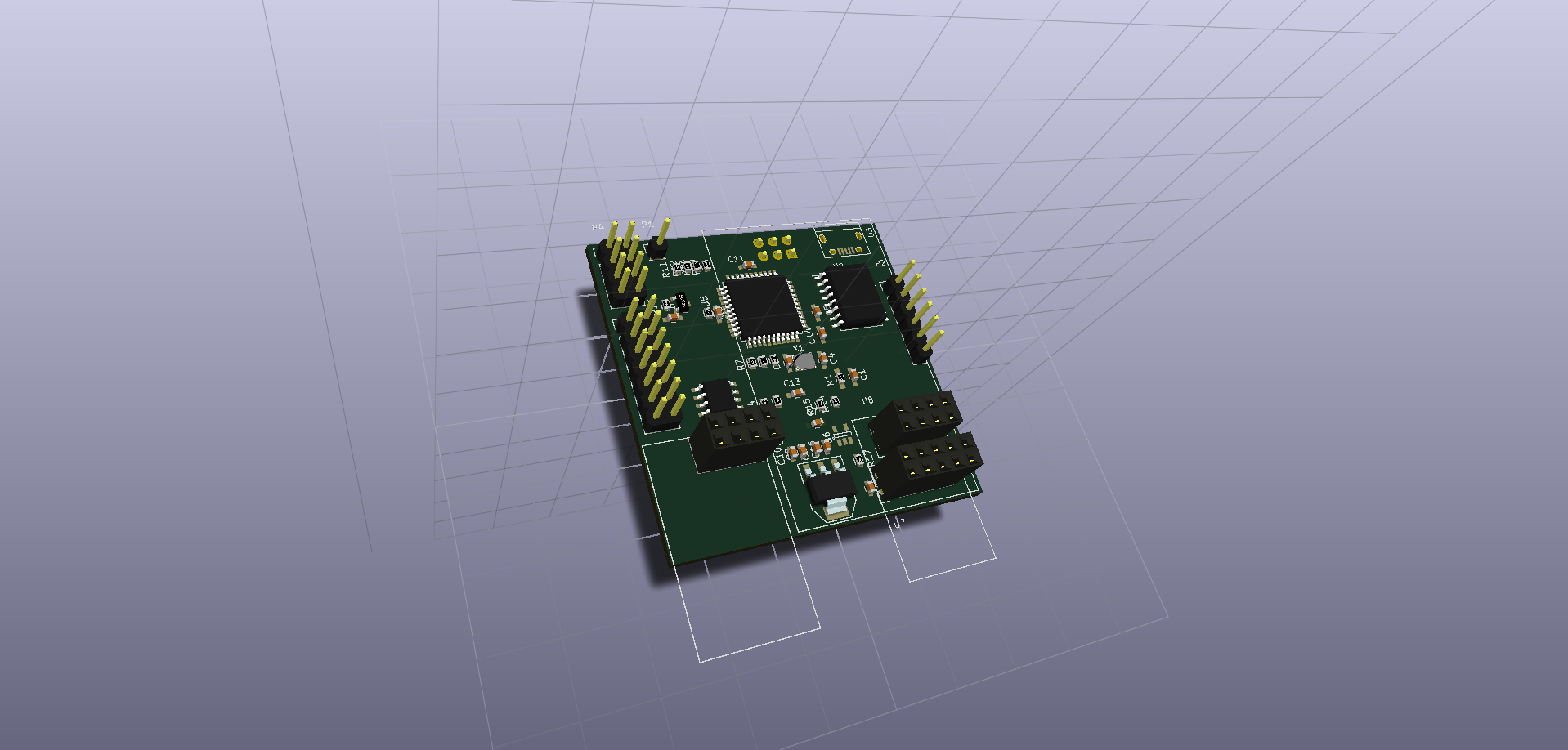
It's designed so that antennas for NRF module / ESP8266 is hanging over the edge on the board (in the bottom of the picture), and W5100 board is having the ethernet connector besides the micro usb connector (which is top right of the picture). ISP programming header is located on the bottom side of the PCB, as it's only needed for initial development.
This is still a conceptual thing though..
So any comments, please? :)
-
KiCad FTW! :)
Looks good to me. I have been able to run the ATSHA SDA pin without a pull without problems but I do know Atmel recommends it so I guess it might be good to have. It should not need to be of any high precision so it ought to be cheap.
-
It doesn't cost anything to add footprints for extra pullup resistors, or decoupling caps. (Other than some time placing them). So I am throwing it in wherever I can..
I have sticked with 0603 components btw. So it should be easier to hand solder the first prototypes :)
The board is still 5x5 cm, probably being 4 layer so I can get room for all the wiring.
@tbowmo
Ah, did not see a no-mount indicator for it so I assumed it would be mounted by default. I agree on keeping all options open if space allows for it.
Yes, you probably have to go 4-layer on that. I had some trouble fitting the routs on my sensorboard in that space. And it has less components. -
I'm sure I missed it but..... as it stands this can be used as a serial gateway correct?
-
I don't own a 3d printer either. it's a secondary thing for me (I'm not that much into mechanical design, I let others do that part :))
@Anticimex
It should be able to have both radios connected, yes.. But what about available codespace? (Ok, we've got 4 times as much space as in the 328p).The 1284p exist in DIP style, http://dk.mouser.com/ProductDetail/Atmel/ATMEGA1284P-PU/?qs=K8BHR703ZXgaD0L1rKdwiQ%3D%3D Can't be any more breadboard friendly than that :)
The wifi option is actually @hek's idea. And if we are going to make a pcb, it wouldn't hurt to make it possible, if someone wants to use it.
I had briefly looked at PoE, but got scared away by the specifications for it :) Think that it's around 48V, and using special magnetics (if you are going to be standards compliant). So need a good switchmode stepdown converter from 48V to 5V. But as it's still on the conceptual state in my head, we might be able to find something that makes it "easy to implement".
Of course size is not that big an issue here.. But 5x5 is standard for small batch pcb's from many of the cheap china board houses. that's why I would aim at that size.
Prototyping area could be an option. Also was thinking about throwing in a sensors or two. Again, it's a concept that has to evolve a bit.. Getting inputs and let it sink in, in order to make an awesome board :)
re: PoE supply
http://www.freetronics.com.au/products/power-over-ethernet-regulator-8023af#.VWCsPLmqqko
is cheap and easy you may be able to piggy back it on the board.
hope it helps
phil -
@ServiceXp
It could be used as serial gateway, there's a ftdi chip onboard. But also place for Ethernet and WiFi connections, together with both nrf24 module and a rfm69 module.
Made to be as versatile as possible.
Ethernet is an add-on module, so a bit hard to implement Poe circuitry on this board. If we could find w5100 module with Poe, it might work.
-
I see no reason not to (depending on available space) add footprints for various "standard" sensors in addition to a IO header on the board. I have no idea on what impact it has on the sw to have a gateway report sensor values to "itself" but I see no reason for why that could not be supported (if it isn't already).
End of double-negations ;)
-
What do you define as "standard" sensors?
@tbowmo
Perhaps an unfortunate label. I guess standard footprints would be a better word. I mean footprints for the most commonly used sensor cases. TO-92, DFN and etc. connected such as the typical sensors (1-wire temps and Si7021 like) will "fit". -
Problem is that each sensor has its own pinout, so you can't make generic footprints.
There already is a GPIO header, with 8 pins (4 analog and 4 digital) plus power. So people can make their own daughterboards with sensors. Might convert 2 of them to i2c bus with pull up, and then have si7021 onboard.
-
Have you considered Grove plugs for sensors? This can give flexibility and a large enough number of sensors at a reasonable price.
-
I think a header for daughterboards will go far in terms of flexibility.
-
Nice nice. I am very interested in this as I have more or less decided to swap to RF69 from RF24. Both for range and because I like the concept of having the radio handle the encryption on my signed packets (yep, I am paranoid as hell). Unfortunately, it means my current gateway has to go but I have made a "sensor evaluation board" (got the PCBs, still waiting for components). Once I get the components and can verify all the features I put on it I will publish it in this forum for those interested. It will still rely on Arduino modules and such so it is not the hard-core approach like the Sensebender Micro though.
Hello! It looks like you're interested in this conversation, but you don't have an account yet.
Getting fed up of having to scroll through the same posts each visit? When you register for an account, you'll always come back to exactly where you were before, and choose to be notified of new replies (either via email, or push notification). You'll also be able to save bookmarks and upvote posts to show your appreciation to other community members.
With your input, this post could be even better 💗
Register Login