110v-230v AC to Mysensors PCB board
-
Hi all,
**UPDATE April 17 2016 **
The latest version of this board is available HERE.After spending a few months on this forum and a few prototypes later, I decided I wanted to build a small but cheap PCB which could be placed in either the wall behind the light switch, or above the lamp.
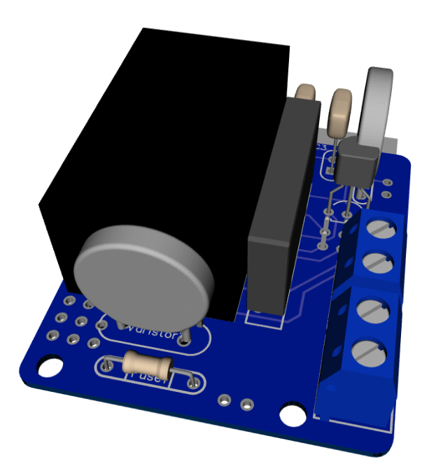
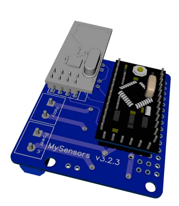
Besides the boards I've seen on this forum, I wanted these boards to contain a module to go from 230v AC to 5/3.3v DC in order to power an Arduino nano and the NRF module. I eventually ended up with a PCB which is about 4 by 4.5cm. So with all components attached I'm hoping to get in stuffed in a 5x5x3cm plastic printed case.
Modules which I've used to power the board:
[http://www.aliexpress.com/item/5-pcs-HLK-PM01-AC-DC-220V-to-5V-Step-Down-Power-Supply-Module-Intelligent-Household/32319202093.html?spm=2114.32010308.4.19.8oKfZgUPDATE: 2015/09/18
As promised, I've got an update for this project. The board has been tested in the past week, and everything is working as expected. Compared to the previous board I've posted, I have updated the following:
• Solder pads of LE33CZ have been placed a little wider apart to avoid short circuit while soldering.
• Solder pads of the resettable fuse (Fuse2) has been placed closer together to better fit the fuses of the BOM.
• Moved the NRF24L01 connector a bit away from the solid state relay. Should make it easier to solder.
• Moved Fuse2 to another location on the board, away from the 230v circuit.Some 3D pictures (Top and bottom):


Anyone who is interested can order the PCB HERE
Some documentation, complete list of required components and all gerber / DipTrace files (in case you would like to make some modifications) can be found here: MySensors board v3.2.3.zip.
-
Hi,
nice project.
your component ref (step down module) is interesting. I think it is a little bigger than china transfo. But i was searching something cheap like this.I have done a relay board too (not tested yet as I am waiting for pcb). It is different. It uses atmel instead nano. But it is 43*38. Maybe I can try to add the step down now I know it, and keep same size.
There is nrf and rfm footprint, astsha, eeprom, acs712, 10amp relay. I will present it when full tested (I have to make some changes). But if you want to see it:
https://github.com/scalz/MySensors-HW/tree/master/OneRelayMysensors
(Note : all my github work is in dev, nothing released, so be careful for the moment. I think i will put it in a dev branch.) -
Hi all,
**UPDATE April 17 2016 **
The latest version of this board is available HERE.After spending a few months on this forum and a few prototypes later, I decided I wanted to build a small but cheap PCB which could be placed in either the wall behind the light switch, or above the lamp.
Besides the boards I've seen on this forum, I wanted these boards to contain a module to go from 230v AC to 5/3.3v DC in order to power an Arduino nano and the NRF module. I eventually ended up with a PCB which is about 4 by 4.5cm. So with all components attached I'm hoping to get in stuffed in a 5x5x3cm plastic printed case.
Modules which I've used to power the board:
[http://www.aliexpress.com/item/5-pcs-HLK-PM01-AC-DC-220V-to-5V-Step-Down-Power-Supply-Module-Intelligent-Household/32319202093.html?spm=2114.32010308.4.19.8oKfZgUPDATE: 2015/09/18
As promised, I've got an update for this project. The board has been tested in the past week, and everything is working as expected. Compared to the previous board I've posted, I have updated the following:
• Solder pads of LE33CZ have been placed a little wider apart to avoid short circuit while soldering.
• Solder pads of the resettable fuse (Fuse2) has been placed closer together to better fit the fuses of the BOM.
• Moved the NRF24L01 connector a bit away from the solid state relay. Should make it easier to solder.
• Moved Fuse2 to another location on the board, away from the 230v circuit.Some 3D pictures (Top and bottom):


Anyone who is interested can order the PCB HERE
Some documentation, complete list of required components and all gerber / DipTrace files (in case you would like to make some modifications) can be found here: MySensors board v3.2.3.zip.
@aproxx what is the size of the step down module? i don't think it was mentioned anywhere but i might have missed it among all the useful data provided.... also, forgive the hopelessly noob question, but how do you connect these modules? are the dots soldering points?
-
-
@aproxx what is the size of the step down module? i don't think it was mentioned anywhere but i might have missed it among all the useful data provided.... also, forgive the hopelessly noob question, but how do you connect these modules? are the dots soldering points?
@aproxx found the datasheet http://www.hlktech.net/product_detail.php?ProId=54
its 34x20.2x15 and there are legs at the bottom -
@aproxx also re-read my post and it might have come out bad - I didn't mean to criticize your data - I meant that on aliexpress they dumped heaps of data a bit badly formatted so it was hard to find things. apologies...
-
Thanks for the positive feedback already! Last night I managed to replace some of the components in order to fit some extra pin-outs in case it is needed.
I still need to test the AC/DC converter+stepdown module, but I have high hopes on this one. I know that really cheap China transfos are cheaper and a bit smaller, but I'd rather go for something a bit more expensive, hopefully has a bit better components and has short circuit protection (it is supposed to be powered on for years and years).
@scalz , you project absolutely seems interesting as well! Unfortunately I don't feel confident enough to do any SMD soldering, so I'm currently sticking to regular Arduino Pro Mini Boards. Maybe I'll try adding an SMD microcontroller and relay in the future.
@Moshe-Livne No worries. AliExpress sure ins't the best source to get specific device information. Glad you found the datasheet!
-
It was another discussion http://forum.mysensors.org/topic/687/230v-power-supply-to-arduino/23
You are adding a valuable solution.
This module looks very interesting in case it will meet all stated characteristics,I also thinkin on something small to fit into standard wall box but I have some complication.
I need a solution for 2-wire lighting, It is because All lighting in my house is a two-wire system.
Otherwise I will need to feed third wire to each wall box. -
@aproxx : of course I am interested with your files. It could be useful.
@axillent : when you say 2-wire lighting, do you mean for one main??? I have done some tests last month to make something like fibaro fgd211. But I jumped onto another project. I had problems I remember. To test I was using a little china transfo and incandescent bulb. First test, zero cross detect with triac. Arduino rebooted always at start (I think about drop voltage and brownout reset arduino, because of a reset of the transfo. but not sure it was that, or maybe it was a no good zerocross....). Then I tried with mosfet pwm. Arduino booted right, but when I increased pwm to something like 192-200, arduino resetted. So I was thinking to use lnk306 but no time (and I think lnk306 need same input voltage so I don't know if it could resolve the problem. So I now am thinking to disconnect my light network and connect it to dc 48 and using led instead.
Do you have idea, to power (steal energy) nodes with one main??? -
If you have a look at the datasheet you see:
All voltage input (AC: 90 ~ 264V)
110 should work.
-
If you have a look at the datasheet you see:
All voltage input (AC: 90 ~ 264V)
110 should work.
@Andreas-Maurer Thats Great. You may want to change the title to reflect that.
-
@scalz
May I make a suggestion? I would look for a solution for both 230v AND 120v for us yanks.. :-) I know I would make the purchase.@ServiceXp : are you talking about my relay board? if yes, I will check what I can do in the end of the week and post my project in a new topic (I think I have to rearrange the board to fit the step down).
-
@scalz two wire ligting menas that a wall switch is feeded only with two wires. One wire is a L source and second wire is from the load (from the lamp). Classical switch just need to short this two for the light to startup. In this case ay smart switch need some advanced technique on to power itself. For example fibaro dimmers do so.
Do you plan to use single 48V power supply for the lighting? I'm working on the prokect for the guest house because it is just on building stage. I have a plan to use single 48V AC-DC power source with wired mysensors network. I will use 3 wires accross all lamps and switches and sensors. They will communicate with each othe P2P using a single wire interface based on Manchester encoding. I also plan to have Mysensors gateway.
-
@axillent Ok. thank you. At my home it is like that. sure it needs a smart switch. and fibaro seems to be very smart (very small, small transfo, and steal energy, but z wave so I think it may use sync comm to use less energy. Maybe I am wrong and don't know how it is inside).
You are right. I am thinking to use 48v power supply lighting. But I cannot change my electrical network. So two wire. And I hope it will be easier to steal energy and power the in wall switch node for leds. Maybe I am wrong. I will power my lightings with energy harvesting (solar, or maybe I have another idea but i have to make experiments.Your lighting project is very smart too. can't wait to see it too.
-
@ServiceXp : are you talking about my relay board? if yes, I will check what I can do in the end of the week and post my project in a new topic (I think I have to rearrange the board to fit the step down).
-
@ServiceXp , I'm also looking for a way to power a node from the available-standard two wire switch. It should be possible to steal some milliamps from there, but I don't know even from where to start researching it.
-
Hi All,
I'm not sure if I understand the 2-wire thing completely, but in my house (which is kind of standard I guess in Europe) I have 3 wires going from the electricity cabinet, to the light switch and then to the light bulb. These cables are Phase, Neutral and Ground.
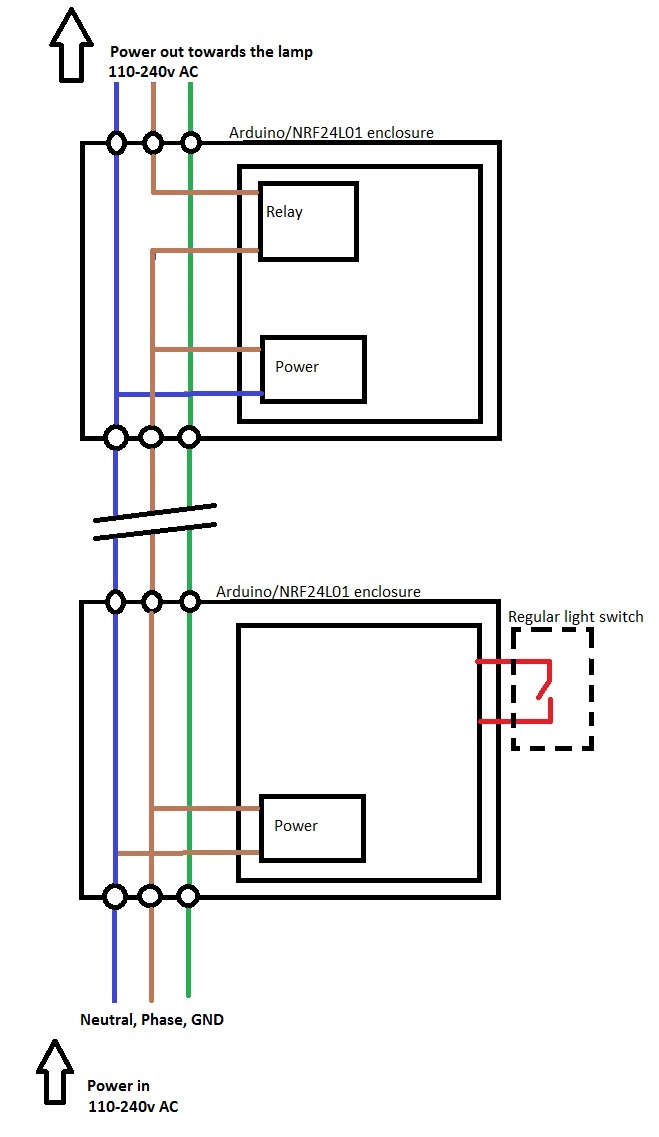
As I don't want to rewire my entire grid, I decided to build these boards so I can reuse the current wiring. I ended up with the following "schematic" if I can call my paintskills like that.
The enclosure at the bottom of the drawing would be placed behind the current light switch, while the enclosure at the top of the drawing would be placed right above the light bulb. This requires little to no modification of my current wiring.
@ServiceXP, I'll update the title to include the 110v information.
-
Why don't you place the relay behind the switch, too? This way you could save half of the nodes.
I have just ordered some of those power supply modules. Very interesting, cheapest similar ones I found before were about 14 €.
