New library to read Arduino VCC supply level without resistors for battery powered sensor nodes that do not use a voltage regulator but connect directly to the batteries ;-)
-
@axillent You're right, but I implemented it like the external voltage dividers I've seen in sketches.
I'll add a configurable lower bound to the interface. -
I don't see how this technique saves any resistors or battery drain. I see there being two different measurements - input to a voltage regulator and input VCC to the uC, which are measured differently.
By "this technique" I mean using VCC as the analog reference (as usual) and reading the internal 1.1V internal source. That gives you 1.1v as a fraction of VCC, so you can easily calculate VCC..
The two measurements:
-
You want to measure regulator INPUT voltage. You typically use a voltage divider to reduce the regulator INPUT voltage to less than VCC, which is used as the ADC reference. The technique describe here cannot be used for that measurement, so it doesn't save resistors or battery drain.
-
You want to measure regulator OUTPUT voltage - or raw voltage if there is no regulator - as applied to the uC for VCC power. The technique described is the way to go, and a voltage divider is inappropriate.
If you used a voltage divider on VCC (case 2) and measured it against the normal VCC reference, all you'd get is a fixed value determined by the resistors, not reflecting VCC.
Summary: if (1) you want to measure regulator input, use a voltage divider, but if (2) you want to measure VCC then use this (well known) technique. Neither approach substitutes for the other. And you can use both, if you want both measurements (eg: if you are concerned about regulator drop-out).
Side note. There are yet other approaches. You could use the 1.1v source as REFERENCE for the ADC instead of VCC, and on the ADC input use a voltage divider from VCC or from regulator input, with a large enough ratio to bring the measured voltage down to less than 1.1v. If you had a 5v processor fed via regulator from a 7.2v source, you could measure the former with a 4:1 resistor ratio and the latter with an 6:1 or greater ratio. This is not commonly done.
If you DO use a voltage divider for measuring voltage (when appropriate), you can reduce the current wasted by using large resistors in the hundreds of Kohm range, AND putting a cap across the lower resistor. You need the cap to reduce the effective impedance into the ADC. If you just use large resistors, the internal capacitance of the ADC circuitry will be charged too slowly during measurement.
-
-
@axillent
Off-topic: why the heck did @hek add support for this temperature sensor to mysensors 1.4 library??? IMHO It doesn't belong there at all!from my experience this temperature sensor is very useless for any sens purpose
you probably will get an acceptable result after calibration, but calibration itself will kill any benefit
it is much easier to use an external pre-calibrated sensor@Yveaux said:
Off-topic: why the heck did @hek add support for this temperature sensor to mysensors 1.4 library??? IMHO It doesn't belong there at all!
I think the internal ATMega temperature can be useful in some circumstances.
Obviously if your goal is to measure weather, there are much better external sensors. But if your sensor is primarily detecting motion or open doors or controlling relays whatever, you may not always have an external temperature sensor included - but you always have a internal one, for free - albeit low accuracy.
Or if you do have an external temperature sensor, the internal temp could be used as a sanity check - if in your physical setup the processor should be close to the same temperature as the external sensor, but the two are way off, something needs to be checked. A bit of monitoring both could tell you the normal range of divergence. Again, this is free - no extra board space or cost.
Another use case is processor monitoring, The internal sensor is actually better at telling you the die temperature, if there's any chance of it overheating (whether or not there is an external sensor), If the board is sealed, just how hot does it get inside the box? If you are putting out a lot of current on a lot of outputs, is the processor heating up? (For weather you'd have the external sensor outside the box and wouldn't know the inside temp).
Yeah, it can be optional, but but the internal temperature is not worthless.
-
I don't see how this technique saves any resistors or battery drain. I see there being two different measurements - input to a voltage regulator and input VCC to the uC, which are measured differently.
By "this technique" I mean using VCC as the analog reference (as usual) and reading the internal 1.1V internal source. That gives you 1.1v as a fraction of VCC, so you can easily calculate VCC..
The two measurements:
-
You want to measure regulator INPUT voltage. You typically use a voltage divider to reduce the regulator INPUT voltage to less than VCC, which is used as the ADC reference. The technique describe here cannot be used for that measurement, so it doesn't save resistors or battery drain.
-
You want to measure regulator OUTPUT voltage - or raw voltage if there is no regulator - as applied to the uC for VCC power. The technique described is the way to go, and a voltage divider is inappropriate.
If you used a voltage divider on VCC (case 2) and measured it against the normal VCC reference, all you'd get is a fixed value determined by the resistors, not reflecting VCC.
Summary: if (1) you want to measure regulator input, use a voltage divider, but if (2) you want to measure VCC then use this (well known) technique. Neither approach substitutes for the other. And you can use both, if you want both measurements (eg: if you are concerned about regulator drop-out).
Side note. There are yet other approaches. You could use the 1.1v source as REFERENCE for the ADC instead of VCC, and on the ADC input use a voltage divider from VCC or from regulator input, with a large enough ratio to bring the measured voltage down to less than 1.1v. If you had a 5v processor fed via regulator from a 7.2v source, you could measure the former with a 4:1 resistor ratio and the latter with an 6:1 or greater ratio. This is not commonly done.
If you DO use a voltage divider for measuring voltage (when appropriate), you can reduce the current wasted by using large resistors in the hundreds of Kohm range, AND putting a cap across the lower resistor. You need the cap to reduce the effective impedance into the ADC. If you just use large resistors, the internal capacitance of the ADC circuitry will be charged too slowly during measurement.
@Zeph Your statement that there are two cases to be considered is right.
A small ceramic bypass cap (say 0.1 uF) is also important on the Voltage dividers to minimise ADC measurement errors due to any noise on these high impedance nodes. Cheap electrolytics are not applicable.
Also need to watch the settling time when switching the multiplexor - need at least 5 msec (or more; depends on size of cap connected to Vref pin):
http://capnbry.net/blog/?p=167
and see the heading "Changing reference voltage" here:
-
-
@Yveaux said:
Off-topic: why the heck did @hek add support for this temperature sensor to mysensors 1.4 library??? IMHO It doesn't belong there at all!
I think the internal ATMega temperature can be useful in some circumstances.
Obviously if your goal is to measure weather, there are much better external sensors. But if your sensor is primarily detecting motion or open doors or controlling relays whatever, you may not always have an external temperature sensor included - but you always have a internal one, for free - albeit low accuracy.
Or if you do have an external temperature sensor, the internal temp could be used as a sanity check - if in your physical setup the processor should be close to the same temperature as the external sensor, but the two are way off, something needs to be checked. A bit of monitoring both could tell you the normal range of divergence. Again, this is free - no extra board space or cost.
Another use case is processor monitoring, The internal sensor is actually better at telling you the die temperature, if there's any chance of it overheating (whether or not there is an external sensor), If the board is sealed, just how hot does it get inside the box? If you are putting out a lot of current on a lot of outputs, is the processor heating up? (For weather you'd have the external sensor outside the box and wouldn't know the inside temp).
Yeah, it can be optional, but but the internal temperature is not worthless.
-
I don't see how this technique saves any resistors or battery drain. I see there being two different measurements - input to a voltage regulator and input VCC to the uC, which are measured differently.
By "this technique" I mean using VCC as the analog reference (as usual) and reading the internal 1.1V internal source. That gives you 1.1v as a fraction of VCC, so you can easily calculate VCC..
The two measurements:
-
You want to measure regulator INPUT voltage. You typically use a voltage divider to reduce the regulator INPUT voltage to less than VCC, which is used as the ADC reference. The technique describe here cannot be used for that measurement, so it doesn't save resistors or battery drain.
-
You want to measure regulator OUTPUT voltage - or raw voltage if there is no regulator - as applied to the uC for VCC power. The technique described is the way to go, and a voltage divider is inappropriate.
If you used a voltage divider on VCC (case 2) and measured it against the normal VCC reference, all you'd get is a fixed value determined by the resistors, not reflecting VCC.
Summary: if (1) you want to measure regulator input, use a voltage divider, but if (2) you want to measure VCC then use this (well known) technique. Neither approach substitutes for the other. And you can use both, if you want both measurements (eg: if you are concerned about regulator drop-out).
Side note. There are yet other approaches. You could use the 1.1v source as REFERENCE for the ADC instead of VCC, and on the ADC input use a voltage divider from VCC or from regulator input, with a large enough ratio to bring the measured voltage down to less than 1.1v. If you had a 5v processor fed via regulator from a 7.2v source, you could measure the former with a 4:1 resistor ratio and the latter with an 6:1 or greater ratio. This is not commonly done.
If you DO use a voltage divider for measuring voltage (when appropriate), you can reduce the current wasted by using large resistors in the hundreds of Kohm range, AND putting a cap across the lower resistor. You need the cap to reduce the effective impedance into the ADC. If you just use large resistors, the internal capacitance of the ADC circuitry will be charged too slowly during measurement.
@Zeph said:
- You want to measure regulator OUTPUT voltage - or raw voltage if there is no regulator - as applied to the uC for VCC power. The technique described is the way to go, and a voltage divider is inappropriate.
This is exactly the use-case where I wrote the library for, or when you want to add supply level measurement to a battery powered sensor node which doesn't have a voltage divider circuit.
Possibly I didn't make that clear in the subject.
Update changed topic subject
-
-
@Yveaux said:
Off-topic: why the heck did @hek add support for this temperature sensor to mysensors 1.4 library??? IMHO It doesn't belong there at all!
I think the internal ATMega temperature can be useful in some circumstances.
Obviously if your goal is to measure weather, there are much better external sensors. But if your sensor is primarily detecting motion or open doors or controlling relays whatever, you may not always have an external temperature sensor included - but you always have a internal one, for free - albeit low accuracy.
Or if you do have an external temperature sensor, the internal temp could be used as a sanity check - if in your physical setup the processor should be close to the same temperature as the external sensor, but the two are way off, something needs to be checked. A bit of monitoring both could tell you the normal range of divergence. Again, this is free - no extra board space or cost.
Another use case is processor monitoring, The internal sensor is actually better at telling you the die temperature, if there's any chance of it overheating (whether or not there is an external sensor), If the board is sealed, just how hot does it get inside the box? If you are putting out a lot of current on a lot of outputs, is the processor heating up? (For weather you'd have the external sensor outside the box and wouldn't know the inside temp).
Yeah, it can be optional, but but the internal temperature is not worthless.
@Zeph said:
I think the internal ATMega temperature can be useful in some circumstances.
Again, I did not want to question the (accuracy of the) internal temperature sensor, but had my questions about the location of the sensor readout code.
MySensors is a wireless networking library, which has in its basic functioning nothing to do with temperature, or any othe measurements.It should deliver the messages from A to B and back. Nothing more.
When it makes sense to use the internal temperature sensor in your sensor node, please do, but put the code in a separate library please! (I know at least @hek understood the point of my remark ;-) )
-
@Zeph said:
- You want to measure regulator OUTPUT voltage - or raw voltage if there is no regulator - as applied to the uC for VCC power. The technique described is the way to go, and a voltage divider is inappropriate.
This is exactly the use-case where I wrote the library for, or when you want to add supply level measurement to a battery powered sensor node which doesn't have a voltage divider circuit.
Possibly I didn't make that clear in the subject.
Update changed topic subject
@Yveaux
OK, I understand your purpose now. I was thrown off by the comparison to using a voltage divider, which seemed to suggest this approach eliminated the need for a voltage divider and the current it costs. I don't see this technique as having an advantage over the voltage divider technique, but rather that it is used for a different measurement.Now that everybody is clear on that - thanks for the contribution!
-
@Zeph said:
I think the internal ATMega temperature can be useful in some circumstances.
Again, I did not want to question the (accuracy of the) internal temperature sensor, but had my questions about the location of the sensor readout code.
MySensors is a wireless networking library, which has in its basic functioning nothing to do with temperature, or any othe measurements.It should deliver the messages from A to B and back. Nothing more.
When it makes sense to use the internal temperature sensor in your sensor node, please do, but put the code in a separate library please! (I know at least @hek understood the point of my remark ;-) )
, but had my questions about the location of the sensor readout code.
When it makes sense to use the internal temperature sensor in your sensor node, please do, but put the code in a separate library please! (I know at least @hek understood the point of my remark ;-) )
OK, thanks for making that very clear and now that I understand, I agree!
In terms of whether there can be some value to even the uncalibrated internal temp, my point was that there are some reasonable use cases for it. In terms of where to put the code in those cases, yes it makes sense to optionally make this one of the reported values in a sensor node, rather than wiring it into the transport library.
-
If I understand this method correctly, you want to read the VCC of the MCU? But this does not have to be the actual battery voltage. Most battery powered designs I have seen here uses a step-up converter to drain the battery as much as possible while maintaining a regulated voltage supply to the MCU. So even if battery voltage drops, MCU gets it's nominal voltage, and then this algorithm would still (incorrectly) report 100% even though the actual battery voltage is dropping significantly.
I could have misinterpreted things though, so I would appreciate correction :)
I would rather consider using the original resistor divider proposal combined with a FET or similar to be able to control when I want to do the measurement. The original simpler design I find a bit too wasteful as it constantly drains the battery.
Or perhaps there are battery management circuits that can do both step-up regulation combined with input sensing that can interface with the MCU to be able to get some real meaty metrics of the battery? Might be expensive, but cool :)
@Anticimex said:
I would rather consider using the original resistor divider proposal combined with a FET or similar to be able to control when I want to do the measurement.
That sounds like a plan :)
I don't want to hijack this thread but can you give an example (schema) of this?
-
@Anticimex Ok, updated the thread subject once more ;-)
-
I have not done the maths for it but just off the top of my head, I was imagining something like this:
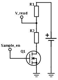
The resistance of the FET needs to be taken into account, and R1 and R2 also should be biased to allow the FET to be kept in firm saturation, but this should allow for a minimum current leakage when the "sample_en" output from the MCU is driven low.
P.S. if you are curious on the schematic, I made it online using SchemeIt by DigiKey. Quite nice if you want to scribble down a decent schematic to do a forum post :)
-
-
I have not done the maths for it but just off the top of my head, I was imagining something like this:
The resistance of the FET needs to be taken into account, and R1 and R2 also should be biased to allow the FET to be kept in firm saturation, but this should allow for a minimum current leakage when the "sample_en" output from the MCU is driven low.
P.S. if you are curious on the schematic, I made it online using SchemeIt by DigiKey. Quite nice if you want to scribble down a decent schematic to do a forum post :)
@Anticimex Thank you very much!!!
-
Like the schematic drawing program - that's good.
Not sure that all this effort is needed. We're only looking at 1uA8 with 470K and 1M divider at 2V6. If large value resistors are used, then don't forget the high quality (low leakage) bypass capacitor.
@a-lurker said:
Like the schematic drawing program - that's good.
Not sure that all this effort is needed. We're only looking at 1uA8 with 470K and 1M divider at 2V6. If large value resistors are used, then don't forget the high quality (low leakage) bypass capacitor.
Yes, a bypass of good quality is probably a requirement when tapping the cell directly and with minute currents.
However, I disagree a bit on the need for the extra effort.
The current is small, yes, but it is also constant. As months goes by, this will make a difference, I believe, although a small one. But if I could make my battery last a week longer by just adding a transistor to the unit, I would still do it, and not have to sit there with a bad feeling in my stomach that there is a voltage divider somewhere in my vicinity bleeding precious battery charge. Yes, you can call me anal or an OCD-sufferer ;)
A single transistor is also not that much more work and I believe most sensor nodes won't have a desperate shortage of GPIO. And with or without a FET, some effort will anyway be needed to calibrate the whole setup so the calculation provides a useful result.@marceltrapman You are welcome :)
-
OCD - I'm obsessive about OCD too!! So no problem with the FET approach, as long it's turned off properly, otherwise it will also leak a similar current. But it should be possible to get it work OK. There will be an increased measuring time. eg turn on FET, wait till circuit settles and then measure. While that is occurring, the CPU (and maybe the radio) are drawing full power (thousands of times as much as the divider does). That's also wasted power that needs to be taken into consideration and may outweigh the savings?
Hello! It looks like you're interested in this conversation, but you don't have an account yet.
Getting fed up of having to scroll through the same posts each visit? When you register for an account, you'll always come back to exactly where you were before, and choose to be notified of new replies (either via email, or push notification). You'll also be able to save bookmarks and upvote posts to show your appreciation to other community members.
With your input, this post could be even better 💗
Register Login