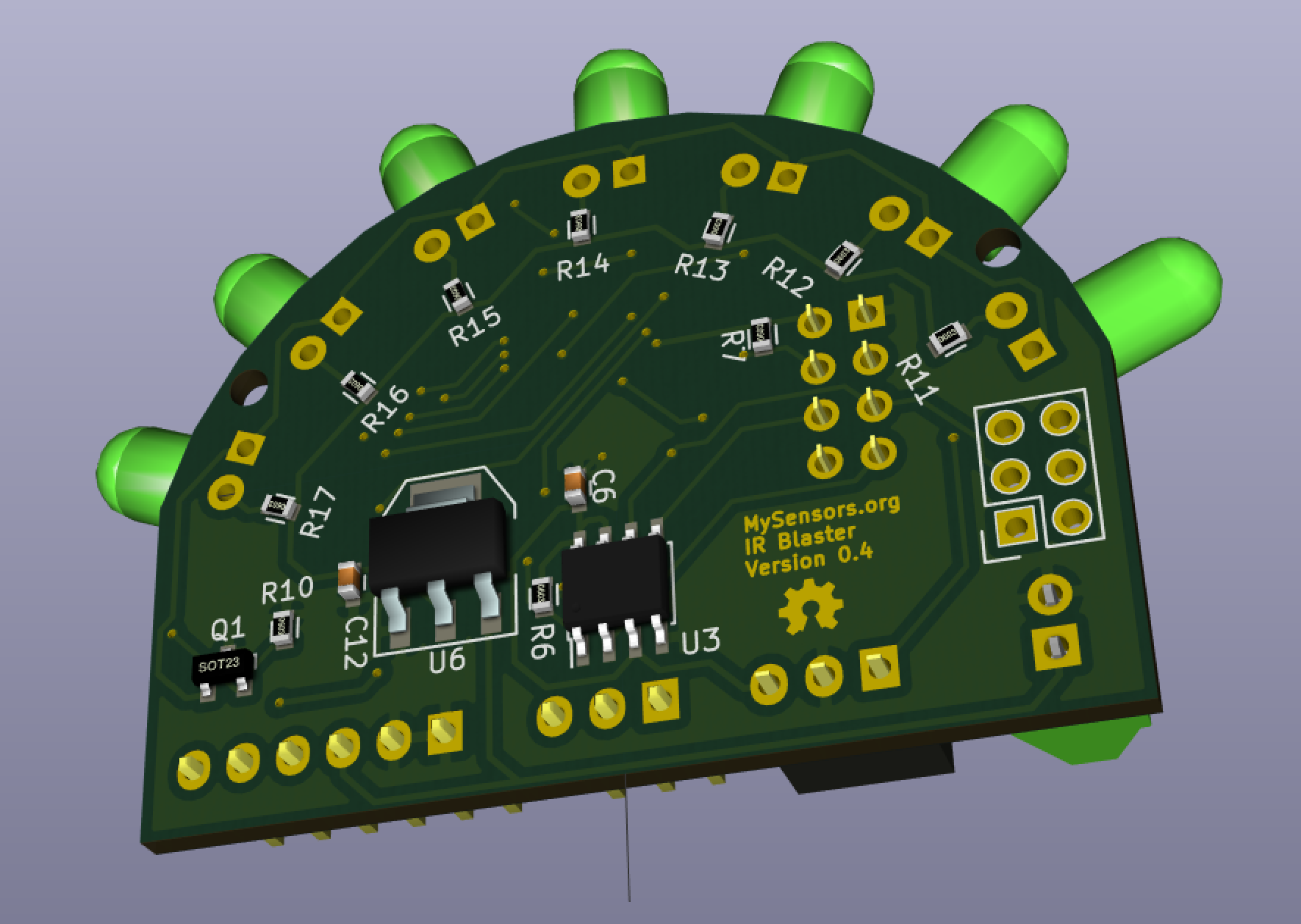
IR Blaster (progress)


  • Admin

    @tbowmo - thanks 👍

    1. Oscillator pads - added to v0.3 schematic (done).
    2. Are you interested in proposing a MySensors common core 3.3VDC regulator circuit? In an ideal world, we would have a single circuit design for power adapters and batteries, when needed, (switching vs. LDO) with enough current output (i.e. ~1A) for circuits that demand it (e.g. parallel IR LEDs). Icing on the cake would be a wide-range of input voltages. For example, when I get back to the multi-channel LED dimmer, it will need to handle 12-24 VDC as input. Are you game?

    @Sparkman - thanks 👍

    1. Thanks for offering to work through the design details for the external emitters. We will need to define constraints for the external emitter performance characteristics IF & VF. If possible, it would be great if we can support IR blocks as well from a single barrel connector.

    2. The goal is to reliably cover a 180 degrees field of view so the blaster can cover an entire room when placed in the horizontal center of a wall or in the corner of a room. To determine the IR LED angle and equal spacing, I defined 6 isosceles triangles that span 180 degrees. This yields the expected directional angles 30, 60, 90, 120, 150. Given the 30 degree difference, one option is to use the higher-luminance 20 degree IR-333-A LEDs for D5, D7 and D9 and interleave the lower-luminance 30 degree IR-333-C LEDs for D6 and D8; of course this means there might be a gap at the extreme edges of coverage (e.g. 0-10 degrees and 170-180 degrees) but that shouldn't be an issue for most users. Furthermore, while we will be driving the LEDs at maximum luminance, coverage holes will open up when the distance exceeds the angular displacement (see screenshots below). That said, I originally limited the blaster to 5 IR LEDs because I was limited to 500 mA through the transistor I selected but since we have now moved to a MOSFET, we can deliver 800 mA to the LED circuit so we could add two more LEDs to reduce the spacing to 22.5 degrees. Adding 2 more IR LEDs will increase the cost (larger board and 2 more LEDs) and I am not sure it is worth it given IR tends to bounce in most interior rooms. We might be better off just selecting different IR LEDs (hence why it is still an open issue). Thoughts (in the context of the tradeoffs)?

    IR LED Angular placement overlaid on board outline

    Screen Shot 2015-05-15 at 8.31.07 AM.png

    20 Degree IR LED

    Screen Shot 2015-05-15 at 8.57.03 AM.png

    30 Degree IR LED

    Screen Shot 2015-05-15 at 8.57.24 AM.png


  • Admin

    @blacey

    Hmm.. I don't have any favourite regulator at the moment. I think that an LDO is the way to go right now (for me) because it's a lot simpler design, and I don't have the needed time to qualify different switchmode designs 🙂

    for the GW I just scavenged the net for 15 minutes, and found a suitable LDO (think it's capable of 0.5A, should probably have one thats capable of higher loads), didn't look that much on the datasheet (yet) as it's still in conceptual phase for me, putting in a couple of extra features each day, moving things around on the pcb, and trying to fit things in.


  • Admin

    @tbowmo Sounds good. For now I will just stick with the AMS1117 series LDO because it is available in both adjustable and fixed (really simple), delivers up to 1A of current, handles up to 12VDC in, the SMD variants are SOT-223 and SOIC-8 and is in expensive. If you find something better, let me know 😉


  • Admin

    @blacey

    Where did you find the symbol for the ams1117? If you created it yourself, could you add it to the mysensors kicad repo on github, so we have a common place for our symbols?


  • Admin

    @tbowmo I created a custom symbol and used the standard SOT-223 footprint from the SMD Packages Library (associated as default footprint for symbol). I just updated the symbol to include a reference to the data sheet and tried to push it to mysensors_regulators.lib in the KiCad repo but it seems I don't have owner/write permission yet 😉 Ping me once you update the permissions and I will push the changes up to GitHub.


  • Admin

    @tbowmo AM1117 pushed to GitHub.


  • Admin

    @blacey

    Thanks 🙂


  • This looks awesome, it's exactly what I'm after to control A/C which I'm having big issues working out I think largely due to having to run on Mega due to very long IR codes.


  • Admin

    My wife and I were in Italy for the past 3 weeks with friends and family so I didn't have much time to work on the IR Blaster actuator. That said, the long flights back and forth from San Francisco to Italy afforded some concentrated time to finalize the design sufficient for public review before procuring a few prototype boards. To goal of this post is to solicit said feedback so "bring it on" after reading the details below.

    @Sparkman - The biggest change is the addition of two more IR LEDs given we are now driving the circuit with a MOSFET (thanks @tbowmo) that can handle higher-current loads; this reduces the risk of IR coverage holes and increases the IR LED component options. However, I have not added a barrel connector for external LEDs to the PCB (yet?) because there are still open issues regarding circuit design to accommodate it (would welcome integration ideas).

    I also have not laid the traces for A0, A1, and A2 because these are completely optional inputs, the 3 traces are difficult to place given the physical PCB layout and in fact they may not survive the final board.

    Everything is in GitHub in case people want to review the details offline.

    The PCB design follows - I had to increase the size of the PCB slightly to accommodate the two additional LEDs.
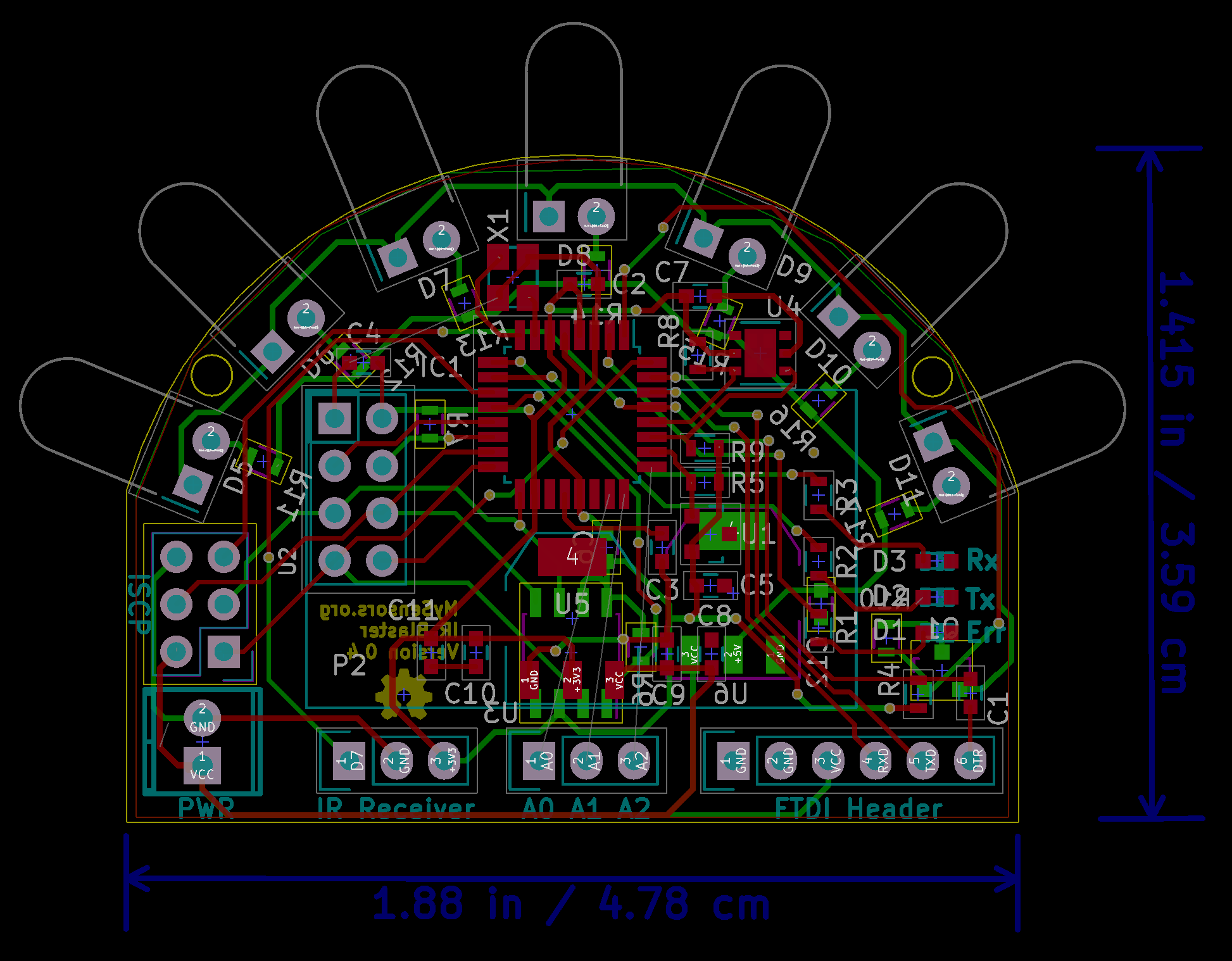
    IRBlasterBoard-v0.4-PCBTrace.png

    Here are two renders of the board, sans the radio daughterboard:
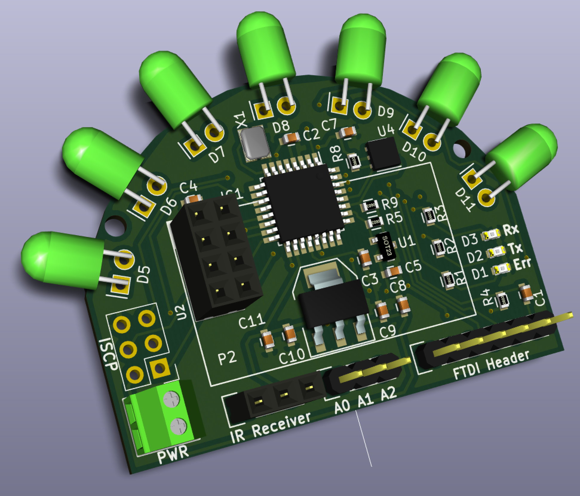
    IRBlasterBoard-v0.4-TopRender.png
    IRBlasterBoard-v0.4-BottomRender.png

    Finally, here is the version 0.4 schematic.

    Schematic v0.4.pdf

    I have also developed a MySensor's IR Sensor Array that will enable me to measure the IR radiant intensity from different points in a room under varying ambient lighting scenarios. The test scenario is that an IR Sensor Array controller will illuminate the IR Blaster and then broadcast to all the IR Sensor Nodes to collect an IR measurement over a specified interval and report the IR level results back to the Sensor Array Controller at which point it will turn off the IR Blaster IRs and log the sensor node results for analysis. This should allow me to select IR LEDs to ensure maximum radiant luminosity without any IR coverage holes/gaps across the 180 degree radiance field. As an interesting side note, the development of the Sensor Array found a messaging limitation in the current MySensors.org library that @hek is planning to address in the next major release.

    Ciao,
    Bruce


  • Hero Member

    @blacey Really lovin this.. You plan to sell?


  • Admin

    @ServiceXp said:

    @blacey Really lovin this.. You plan to sell?

    If there is enough community interest and demand, we (@hek et. al.) will offer the IR Blaster in the same fashion as @tbowmo's pioneering and very successful Sensebender Micro and hopefully in-development Gateway Device that I am personally jazzed about. Any proceeds from IR Blaster hardware sales will go directly to supporting the MySensors.org project (monthly hosting fees, etc.). So to answer that question we need to know who else would buy one if we make it available so we can estimate the batch size for an initial run. Anyone interested is encouraged to weigh in here.


  • Admin

    I would be interested in at least one of them. (I'm thinking if we should add repeater mode into the firmware as a default?)


  • Admin

    @tbowmo said:

    I would be interested in at least one of them. (I'm thinking if we should add repeater mode into the firmware as a default?)

    Cool and I'll sign-up for 4 Gateway Devices 😉 I'm dead serious!

    In my 1st gen one-off IR Blaster, I found that I need to repeat some IR Signals if that is what you mean by "repeater mode". I am using the HA Controller to repeat after some delay but it would make more sense to integrate the repeating logic directly into the firmware. I am planning pretty extensive IR reliability testing with the IR Sensor Array that I mentioned and I hope that repeating won't be necessary but some environments may have sufficient "noise" to require repeating. Perhaps it should be configurable (number of repeats and delay)??

    I'm also thinking that a single IR Blaster should be able to control multiple devices in a given room so I'm planning to provide that as out-of-the-box functionality in the firmware. I don't know how I will do that yet but something akin to an array of child-devices that contains the child device type, manufacturer and IR code. The MySensor's library limit is 255 child devices per node so that should be sufficient 😉

    I also think it makes sense to "lift" the self-tests that you developed for the Micro Sensor (flash and crypto chip).

    Finally, I would love your expert review of the design before I order some boards for verification. I owe you a review of the Gateway Device that I will complete this weekend now that I am back on my home turf.


  • Admin

    @blacey

    With the "repeater mode" I actually meant it to be a repeater for the mysensor network, so it double as both repeater and IR blaster.

    Or maybe I would make a dimmer module, that could act as a repeater as well (I would add a couple of network repeaters around the house, as I have discovered some partially dead spots around here, where sensors are just on the edge of the reach of the RF signals)


  • Hero Member

    @blacey i would buy 6 of these if they can reproduce my heatpump/hvac codes....


  • I would be in for one, possibly two for media control.


  • I would be good for two.
    Great idea


  • I would like to buy at least one for TV/Dishtv


  • Admin

    I want to buy one as well.


  • I would be in for at least 3, probably 5!


  • Hardware Contributor

    I also wants to buy 1-3 depending on price.


  • I want to buy one


  • Hero Member

    I am interested allso.


  • Hero Member

    I'm in for at LEAST 1, but most likely ... MORE... 😛


  • 3 to 5 here


  • Contest Winner

    I'm in for a couple too...


  • Two for me please.


  • Mark me down for 1!


  • Hero Member

    one for me!


  • I would also take 5


  • I am interested in at least one, maybe two depending on area coverage.


  • Admin

    Placed an order for the first prototype boards today... Sourcing from China to U.S. so it will take a while for them to arrive from the fab but I will keep everyone apprised of the progress. That said, here is a render of the protoboard (v0.5) with NRF24L01+ attached to provide a sense of the board's physical size/footprint (thanks to @tbowmo for the NRF24L01+ 3d-shape).

    Screen Shot 2015-06-25 at 4.32.36 PM.png


  • Hero Member

    @blacey do you know of any reliable way to record and play very long code, like HVAC ones?


  • Mark me down for 1 as well.


  • Admin

    @Moshe-Livne

    @blacey made room for an external flash on board, which probably could be used to store IR codes.

    The flash that he chose is a 64Kbyte (512kbit), so only the first half of the flash is actually used for OTA updates, which leave us 32Kb external flash storrage available for the user.


  • Hardware Contributor

    @blacey: very nice design. I think there will be mysensors production for your board as people are interested... And me too, I can't wait to see all sketches and usecases...
    In future, it will be great as I feel there is a hardware design movement for Mysensors, very interesting.


  • If I am understanding this thread correctly. This would be capable of repeating the IR signal, correct? So, if I put one of these in every room. I can use my universal remote or something similar to change the channel on a tv in another room?


  • Admin

    @gigaguy

    Yes that could be one possible use-case.

    Normally (I would imagine) the blaster would pick up your remotes commands and send them to the controller. What you actually do with this information (on the controller side) is up to you. You might wanna send a command to the z-wave controlled curtains to open. Or turn on the lights in certain rooms.

    Another usecase could be to create a scene (on the controller) that turns on the tv (or fake-fireplace!) at 7pm every evening.

    I'm thinking of pausing the tv when someone calls (as I've got the ip-telephone integrated in my HA soulution)...


  • Yes there are many possibilies and I like the design of the board (looks great). We have create a similar device (only on a breadboard at the moment), which has also include RF433 receive and transmit function and we can controlled it by voice. Each IR code is stored in a txt file on a SD card (raw code). A bit hard for me to explain it here with words, but I can record a video how it works in real if anyone will see it in action.
    It has only one disadvantage - you need two Nano or Mini on a PCB board.


  • Hero Member

    @kalle its not that bad with minis costing few $ each....


  • Ok, here we go a short video demonstration: www.youtube.com/watch?v=y38oIZgV_cU


  • at least one for me


  • Plugin Developer

    Any one tried using IR transmitter to send IR signal to AC with mini pro ( 328p ) as mysensor node. I know mini pro have limited ram / rom support.

    Note: AC remote send long IR signals which may not be completely captured by IR receivers connected to mini pro. may be one try on rasp pi but that's a last resort.


  • Hero Member

    @blacey said:

    @Sparkman - The biggest change is the addition of two more IR LEDs given we are now driving the circuit with a MOSFET (thanks @tbowmo) that can handle higher-current loads; this reduces the risk of IR coverage holes and increases the IR LED component options. However, I have not added a barrel connector for external LEDs to the PCB (yet?) because there are still open issues regarding circuit design to accommodate it (would welcome integration ideas).

    Sorry for the slow response Bruce, it's been crazy busy at work and a few projects around the house. I have a few days off in a row now so will finish testing. The circuit board design looks great and I'd be interested in a few as well based on current design.

    Cheers
    Al


  • Admin

    @kalle - nice innovation and great demo! 👍


  • @blacey I got my checkbook ready put me down for 2!


  • Admin

    @Sparkman said:

    Sorry for the slow response Bruce, it's been crazy busy at work and a few projects around the house. I have a few days off in a row now so will finish testing. The circuit board design looks great and I'd be interested in a few as well based on current design.

    Al, no worries, I know the crazy busy drill! 😉 I hope the work and home projects went well - let me know what you determine based upon your testing.


  • Admin

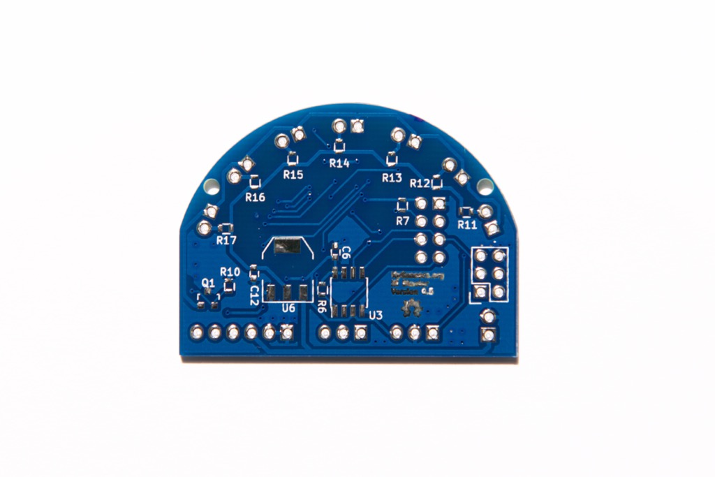
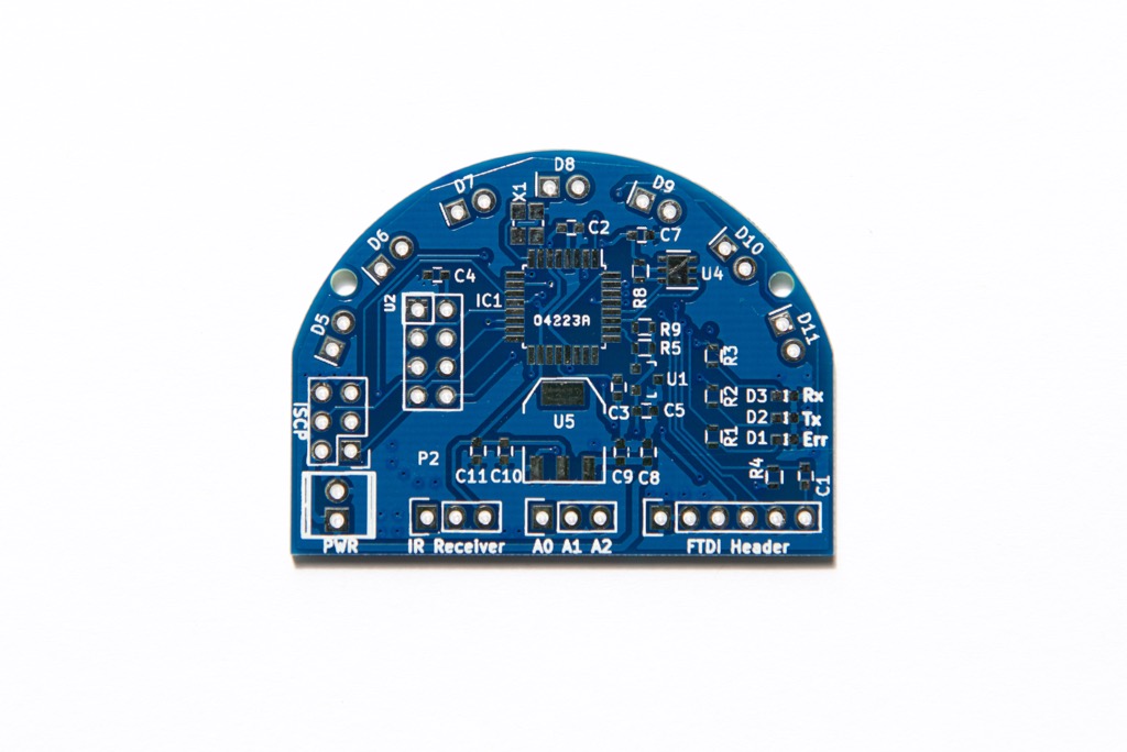
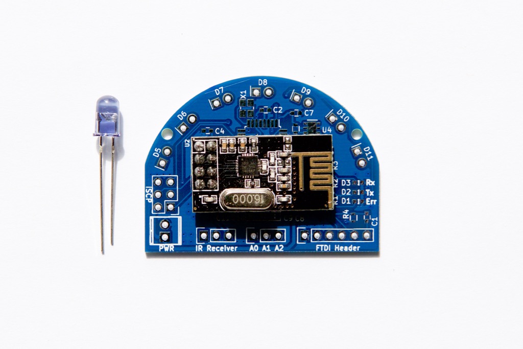
    First board revision just arrived from the fab house in China! Boards look good other than the MySensors IR Blaster v0.5 that I placed in the solder paste layer instead of the silk screen layer because the font is too small. Unfortunately the fab house was quicker than I because I haven't even had a chance to finalize the BOM and order the components. Need to get that in gear so I can assemble the first board early next week.

    Top of Board
    DSC_1012.jpg

    Bottom of Board
    DSC_1005.jpg

    Board with radio set and LED for relative size perspective
    DSC_1029.jpg


  • @blacey The excitement is brewing! Can't wait


  • @blacey Thanks, I hope I can build my RF/IR blaster in a similar design, because it looks fantastic!

    by the way, you can set me to the buyer list for one 😉


  • Hero Member

    @blacey Looking good!


  • Admin

    @Dheeraj said:

    Any one tried using IR transmitter to send IR signal to AC with mini pro ( 328p ) as mysensor node. I know mini pro have limited ram / rom support.

    Note: AC remote send long IR signals which may not be completely captured by IR receivers connected to mini pro. may be one try on rasp pi but that's a last resort.

    Not yet but take a look at http://www.analysir.com/blog/2014/03/19/air-conditioners-problems-recording-long-infrared-remote-control-signals-arduino/ for a good explanation of what you are probably experiencing. From a hardware stand-point, the IR Blaster should be able handle the longer IR codes, it will just be a matter of adding the required support to the firmware.


  • Admin

    Just ordered all components required to assemble first board rev. Unfortunately Friday (tomorrow) is a holiday in the U.S. so the order won't move until Monday. If all goes well, I will be able to assemble and bring up a first board late next week.


  • Hero Member

    @blacey Thanks. I have not seen this in my searches. looks promising. I'll give their sketch a try and see if it records the codes properly (as far as I can say). all other libs failed miserably.


  • Admin

    @blacey

    Hmm.. If a IR recorder is included in the sketch, how would you handle different carrier frequencies of the remotes?

    It could be anything between 35Khz and 40Khz (or 400Khz if it's B&O equipment), and IR receivers are made with narrow filters. This could mean that if you use 38Khz carrier frequency on equipment that originally uses 35Khz, then because of the attenuation in the filters, the range is very low.

    Ideally we need something to detect the carrier frequency as well.. But don't know if that is possible to obtain easily with an arduino setup


  • Plugin Developer

    @blacey said:

    using IR transmitter

    I have gone through this link, and tried it recommendation of increasing the RAWBUF size and also used sample sketch which was not working for me , may be i was doing something wrong. Also, It uses raw IR signal and handling raw signal is not simple compare to IR hex code which are at max 32 bits. I wish IRlib, IRemote etc support handling of long IR signals. Any library which support it?


  • Hero Member

    @Dheeraj Alas, AC codes are not hex codes as far as I know. they have to be used in raw mode. This whole IR thing is very confusing but from what I gather:
    there are several standard encodings (they are like bar code) that are compatible with binary encoding in the sense that the gap and length are constant so no signal in the period can be 0 and signal can be 1. However, when you want to put more information more quickly (or when you just want to annoy people) you use non standard encoding that is comprise of several lengths of silence and transmission. naturally this is a much more "dense" encoding and if you know the protocol you can easily convert it to short codes. However, we don't and I know of no library that can encode for all AC. every AC and sometimes even different models have different encoding. most of the work that was done was made in the area of home theater so all those codes are known. AC is still a no mans land.
    I do not pretend to really understand this fully, I am just explaining what I think I know so far.


  • Admin

    @tbowmo The board is not tied to a specific IR Receiver - we have a socket on board as a convenience so users can temporarily plug an IR Receiver in to learn the codes the don't have to build an IR learning circuit on a breadboard just to learn the codes. This means that users will be able to use whichever IR receiver is appropriate for their equipment/needs. We will probably include the most common IR Receiver with the IR Blaster kit so it is plug-n-play for 90% of the users out of the box. The last 10% is ideally a longer term software challenge but time will tell 😉


  • Plugin Developer

    @tbowmo said:

    Ideally we need something to detect the carrier frequency as well.. But don't know if that is possible to obtain easily with an arduino setup

    I have tried a lot of things, i ended up with recording the signals and replay them at different frequencies (36,37,38,39 and 40) and rotated the scheme. When someone got a working frequency the signal is stored with the frequency. I ended up with IRremote from http://github.com/shirriff/Arduino-IRremote as it became quite tedious. Maybe it helps.

    Cheers,
    John.

    [edit]Sorry, now seeing that the mentioned lib has already passed by[/edit]


  • Admin

    @John Here is another option - there seems to be a lot of prior art out there that we can leverage. https://github.com/r45635/HVAC-IR-Control


  • Hero Member

    @blacey i tried this one as well but i was wearing wool sweater at the time and it seems like the ir recievers do not take huge zaps well so i have to repeat my experiments when new leds arrive


  • Plugin Developer

    @blacey said:

    @John Here is another option - there seems to be a lot of prior art out there that we can leverage. https://github.com/r45635/HVAC-IR-Control

    Looks like they merged the library i'm using but with hvac additions. Original one i used is here: https://bitbucket.org/pidome/pidome-hardware/src/ce1d656c909b/Arduino/Uno/PiDome IR Tranceiver/?at=default My code is merely a "proxy"(wired) as it is meant to send and receive. This because codes are stored on the server. Maybe it helps. I haven't followed the whole thread, but it would be very nice if the blaster could be used to proxy. But i know raw ir signals can be too long for the mysensors payload.


  • Admin

    Status Update - 2015-07-10

    Ok, so here is the latest on our progress to build an IR Blaster v0.5 first prototype/dev board. I have assembled two dev boards that pass the initial smoke test of power regulation, MCU and status LEDs. Through this process, I have identified a number of changes and improvements to the board none of which blocks bringing up a fully functioning IR blaster (at least not yet so keep fingers crossed). I did find one KiCad Gerber bug that shorted the MOSFET gate trace to the upper ground plane but with an Exacto knife and a little elbow grease, I was able to eliminate the short - if you look closely around D10 and the Err LED, you sill see my handy work 😉

    Photo of the twin v0.5 dev boards.

    Left is top-side board #1 and right is bottom-side board #2
    DSC_1097.jpg

    Short video excerpt of the smoke test running (luckily, without smoke)

    And here is a short video clip of the first board passing initial smoke test proving that the power regulation, MCU and status LEDs are working per design.

    IR Blaster v0.5 Smoke Test

    Next steps (dev prototype v0.5)

    • Verify the off-MCU flash and crypto chip electrical and functional integrity by extending the smoke test sketch to run @tbowmo and @patrick SenseBender Micro built-in tests.
    • Verify the NRF24L01+ electrical and functional integrity - solder socket to board and confirm that the radio comes up with MySensors library
    • Verify MySensors full-functionality - load the latest SenseBender Micro sketch and confirm reporting of humidity and temperature. With the proper MySensors library, the sensor Tx, Rx, and Err LEDs should provide send and receive status accordingly.
    • Verify IR LED circuit by soldering 7 IR LEDs to the board and confirming electrical and functional integrity

    Bottom-line, quite a bit of work left to do but no major blockers encountered so far using two initial dev boards.


  • Hardware Contributor

    So coool, nice board!
    I am making a board (it is another project) and I am like you. just some changes to do. I think we are lucky to pass smoke tests 😄 and just having little changes because human errors are never far away, especially when it is not our field! (not mine, I don't know if you are, but it looks pro)
    So I will cross my fingers with you😉
    and of course I will follow your project with interest as I have the same steps to achieve.
    good luck for next steps.


  • Admin

    First Dev Boards Complete 10-JUL-2015 - status update with video

    I assembled two dev boards yesterday, brought up all subsystems and they are both working great. Still a bit more work to do before they go to production but here are a couple of photos and a demonstration video.

    Assembled dev board w/o radio
    DSC_1131.jpg

    Assembled board w/Radio attached
    DSC_1132.jpg

    Demonstration Video
    https://youtu.be/UXjcwlJOMOI

    I am going to rev the board a bit to pull all components to the top-side to reduce the cost and also subject the boards to the IR Sensor Array testing to tune the IR LED component choice for maximum performance.


  • Any update on the progress. I'm so excited to get one of these blasters.


  • is there any chance of buying some modules? I would like to control my TV-setup with this.


  • Plugin Developer

    This thing would be cool to have. In my setup i would really like to test this as a transceiver for my project.


  • Interested in purchasing a few! Would be perfect int he home theater, I think.


  • Admin

    @gloob, @john, @notYetRated and everyone else - Here is an update on IR Blaster project

    The first dev boards are working well but not as good as they should IMHO. My 0.5 LED circuit design uses a separate voltage-regulated parallel IR LED emitter circuit. After a lot of technical research into the depths of IR Emitters and collaboration with others, I can greatly improve the IR performance by moving to a constant-current (not constant-voltage) serial IR LED emitter circuit. I have been scouring the net for constant current regulators and/or LED drivers that can handle 7 IR LEDs @100ma & 1.6FV and have a few candidates under review for prototyping.

    I have also been in touch with the AnalysisIR guys to ensure compatibility of our board with their offerings because users have successfully decoded long IR encodings, using the advanced AnalysisIR decoding software, such as HVAC units popular in the EU/UK - for example Panasonic AC and Mitsubishi AC. The goal being that any Analysis IR decodes, will be directly compatible with our board so we can leverage the enthusiasm and prior work of the AnalysisIR community at large. In addition, I would like to advance our board to be able serve as a full spectrum IR decoder to ensure maximum decoding performance when using AnalysisIR on the board. Compatibility requires running the MCU at 16MHz or great to improve the IR mark/space decoding which also requires additional changes to the original circuit design.

    All of that said, the reason for the recent silence by me has been due to my personal life - I have had a hectic family pursuit requiring multi-month travel from home and work has heated up again.

    Fear not though, this is an extremely important project for me and I will get it done! While it is taking a bit longer than I had hoped, I firmly believe it will be well worth the wait.


  • Plugin Developer

    @blacey No problem! As long it is possible to have all the IR codes be able to store on the server i'm very interested 😉 Take all the time you need to get it to your requirements


  • @blacey Let me know if I can be of any help. Mostly in the use-case testing area probably, as I am no electrical engineer or software genius. 🙂


  • Any update on this project? Do you need any support to finish this PCB?


  • Hero Member

    @blacey How is the project progressing? I can't wait to get my hands on this. (even though HomeSeer may not be able to incorporate it yet 😉 )


  • Admin

    Apologies everyone but progress has been much slower than I had planned/wished for two reasons. 1) Work obligations and 2) a special automation from my wife that has usurped my MySensors cycles that required helping the FreeCAD open source project to advance my cause. My plan is to hit IR Blaster hard within the next 4-6 weeks.


  • Hero Member

    @blacey
    Did you abandon this project? We are heading for darker times again and I was really hoping that your blaster would be available to turn on those candles in the night.

    Just let me know if you stil have plans to realize this or not so that I know if I should make something for my self on a perfboard or something.


  • Hero Member

    Any news on this?


  • Admin

    I know that @scalz have a blaster project going as well


  • Admin

    @korttoma Apologies to you and others; I wouldn't say that I have abandoned this project but it is fair to say that I haven't had the time to devote to this either so it is woefully stalled. @scalz is working on something similar that may fit but bill nicely after which I will decide whether this warrants further development or not.


  • Hardware Contributor

    @korttoma
    guys are true 🙂
    I'll order next week my pcb. i'm taking the weekend to think about my design. perhaps will do a dhl 😊 as i have other things to order and i'm an impatient child..
    Of course, i'll share my workn and hope to work with @blacey . this will be a Mysensors project 😉


  • Hardware Contributor

    @blacey @scalz
    I'm thinking of starting to do an IR blaster on my own, any chance to get a glimpse of what you are cooking on your side to either wait / see what kind of function you plan?

    On my side I'm thinking of:

    • Eventually esp8266 based (probably using a WeMos mini Pro) to allow a wide range of usage even out of MySensors.
    • Micro usb powered (using the WeMos' port)
    • SMD nrf24L01, eventually RFM too if it fits on the PCB.
    • optional ATSHA.
    • IR leds on the side (roundish PCB?)
    • Optional IR receiver

  • Admin

    @emc2 That pretty much sums up the above sans ESP8266 vs. Atmel 328p... My next iteration, albeit delayed, uses an SMD footprint compatible with both NRF and RFM. I had originally included an Si7021 temperature and humidity sensor but that isn't really necessary. @sparkman had requested a barrel connector to drive external IR LEDs.


  • Hardware Contributor

    @emc2 "almost" same specs on my side, except i'm gonna use esp32 🙂


  • Hardware Contributor

    @scalz Cool! Let me know when you have some details on that. I may stick to esp8266, esp32 seems to be overkill for what I'm thinking, but if you have any tips let me know.

    @blacey I saw this request, I can see the use of it, will see if I end up with a spot for one. One thing still, are these standard in term of where is ground and where is VCC on the mono 3.5mm jack? (I assume GND is "outside" and VCC is the "tip" but I may be wrong)


  • Hero Member

    @emc2 said:

    where is ground and where is VCC on the mono 3.5mm jack

    Googling this gives some different results but this one seems most reasonable:

    alt text

    Picture was taken from here.

    Maybe one jack can be used for both purposes? In learning mode you could have a sensor in the jack and otherwise you could have a IR Blaster in the same jack? Just a thought.


  • Hardware Contributor

    @emc2 hehe. i don't think this is overkill 😉 depends on what features. well let's see how it will work. mine is already designed but i won't have lot of time before beginning of the year now 😁


  • Hardware Contributor

    @scalz said:

    @emc2 hehe. i don't think this is overkill 😉 depends on what features. well let's see how it will work. mine is already designed but i won't have lot of time before beginning of the year now 😁

    Agreed, depends on the features, in my case I did not really think of any additional features, just IR stuff. PCB was designed yesterday, I will play with a protoboard to check if everything works and then will see how to improve everything before ordering.


  • For info, Luminara works with USB-UIRT with windows (Eventghost)

    Code IR ON:
    0000 006F 0000 000A 01DD 0054 00F1 0053 002C 007B 002D 007B 002C 007B 007C 002B 002D 007C 002C 007B 007B 002C 007B 0FF1

    Code IR OFF:
    0000 006F 0000 000A 01DD 0054 00F2 0053 002D 007B 002D 007B 002C 007B 007C 002C 002C 007B 002D 007B 007B 002C 002D 09F6

    With Eventghost you can create request HTTP to Trigger IR signal

    I learned code IR with LM Remote KeyMap beacause EventGhost don't learn signal


Log in to reply
 

Suggested Topics

  • 87
  • 2
  • 8
  • 7
  • 1
  • 5

0
Online

11.4k
Users

11.1k
Topics

112.7k
Posts