New library to read Arduino VCC supply level without resistors for battery powered sensor nodes that do not use a voltage regulator but connect directly to the batteries ;-)
-
If I understand this method correctly, you want to read the VCC of the MCU? But this does not have to be the actual battery voltage. Most battery powered designs I have seen here uses a step-up converter to drain the battery as much as possible while maintaining a regulated voltage supply to the MCU. So even if battery voltage drops, MCU gets it's nominal voltage, and then this algorithm would still (incorrectly) report 100% even though the actual battery voltage is dropping significantly.
I could have misinterpreted things though, so I would appreciate correction :)
I would rather consider using the original resistor divider proposal combined with a FET or similar to be able to control when I want to do the measurement. The original simpler design I find a bit too wasteful as it constantly drains the battery.
Or perhaps there are battery management circuits that can do both step-up regulation combined with input sensing that can interface with the MCU to be able to get some real meaty metrics of the battery? Might be expensive, but cool :)
@Anticimex said:
I would rather consider using the original resistor divider proposal combined with a FET or similar to be able to control when I want to do the measurement.
That sounds like a plan :)
I don't want to hijack this thread but can you give an example (schema) of this?
-
@Anticimex Ok, updated the thread subject once more ;-)
-
I have not done the maths for it but just off the top of my head, I was imagining something like this:
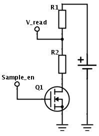
The resistance of the FET needs to be taken into account, and R1 and R2 also should be biased to allow the FET to be kept in firm saturation, but this should allow for a minimum current leakage when the "sample_en" output from the MCU is driven low.
P.S. if you are curious on the schematic, I made it online using SchemeIt by DigiKey. Quite nice if you want to scribble down a decent schematic to do a forum post :)
-
-
I have not done the maths for it but just off the top of my head, I was imagining something like this:
The resistance of the FET needs to be taken into account, and R1 and R2 also should be biased to allow the FET to be kept in firm saturation, but this should allow for a minimum current leakage when the "sample_en" output from the MCU is driven low.
P.S. if you are curious on the schematic, I made it online using SchemeIt by DigiKey. Quite nice if you want to scribble down a decent schematic to do a forum post :)
@Anticimex Thank you very much!!!
-
Like the schematic drawing program - that's good.
Not sure that all this effort is needed. We're only looking at 1uA8 with 470K and 1M divider at 2V6. If large value resistors are used, then don't forget the high quality (low leakage) bypass capacitor.
@a-lurker said:
Like the schematic drawing program - that's good.
Not sure that all this effort is needed. We're only looking at 1uA8 with 470K and 1M divider at 2V6. If large value resistors are used, then don't forget the high quality (low leakage) bypass capacitor.
Yes, a bypass of good quality is probably a requirement when tapping the cell directly and with minute currents.
However, I disagree a bit on the need for the extra effort.
The current is small, yes, but it is also constant. As months goes by, this will make a difference, I believe, although a small one. But if I could make my battery last a week longer by just adding a transistor to the unit, I would still do it, and not have to sit there with a bad feeling in my stomach that there is a voltage divider somewhere in my vicinity bleeding precious battery charge. Yes, you can call me anal or an OCD-sufferer ;)
A single transistor is also not that much more work and I believe most sensor nodes won't have a desperate shortage of GPIO. And with or without a FET, some effort will anyway be needed to calibrate the whole setup so the calculation provides a useful result.@marceltrapman You are welcome :)
-
OCD - I'm obsessive about OCD too!! So no problem with the FET approach, as long it's turned off properly, otherwise it will also leak a similar current. But it should be possible to get it work OK. There will be an increased measuring time. eg turn on FET, wait till circuit settles and then measure. While that is occurring, the CPU (and maybe the radio) are drawing full power (thousands of times as much as the divider does). That's also wasted power that needs to be taken into consideration and may outweigh the savings?
@a-lurker :) yes, cutoff of the FET needs to be handled as well. If nobody beats me to it, I'll whip a testing circuit together to measure the currents, but considering my current schedule I am afraid it will take a few weeks for me to get around to it. I am going to need the better precision meter in my office since any leaks in the FET will be small and difficult to measure properly. But with pen and paper it should be possible to design around it in theory and only measure the "finished" design to benchmark it. I hope to get some time tomorrow to provide an updated schematic with a few values for somebody adventurous to evaluate.
-
OK, now we are recapping the investigation JeeLabs did a year ago.
I recommend these articles:
http://jeelabs.org/2013/05/15/what-if-we-want-to-know-the-battery-state/
http://jeelabs.org/2013/05/16/measuring-the-battery-without-draining-it/
http://jeelabs.org/2013/05/17/zero-powe-battery-measurement/He did test the various circuits and values. The conclusion is that using a FET you can get the current drain even lower, but using 10 Mohm resistors and a cap he got the drain to sub-microamp.
Once you get the drain down that low, the uC sleep current and battery self-discharge and capacitor leakage and any other sensors are going to dominate anyway. An open pin spec'd at +/- 1 uA, so even a sensor pin which you think is disabled may be drawing more current than that.
Still, it can be fun to really go for the minimum possible.
-
@ ZEPH Good links. Pretty much says it all - including that in the cct posted above the divider could have leakage into the ADC I/P when the FET is off.
Something else that's probably important is to measure the Voltage just before going into sleep, rather than when the CPU powers up. This gives a better indication of what the battery condition, because the measurement occurs a little while after the load has been applied to the battery. If you measure when the CPU powers up, the battery has the whole sleep time to "recover" from its last wake up. I'm pretty sure this could be demonstrated by making a start and end measurement and seeing what happens over time.
-
OK, now we are recapping the investigation JeeLabs did a year ago.
I recommend these articles:
http://jeelabs.org/2013/05/15/what-if-we-want-to-know-the-battery-state/
http://jeelabs.org/2013/05/16/measuring-the-battery-without-draining-it/
http://jeelabs.org/2013/05/17/zero-powe-battery-measurement/He did test the various circuits and values. The conclusion is that using a FET you can get the current drain even lower, but using 10 Mohm resistors and a cap he got the drain to sub-microamp.
Once you get the drain down that low, the uC sleep current and battery self-discharge and capacitor leakage and any other sensors are going to dominate anyway. An open pin spec'd at +/- 1 uA, so even a sensor pin which you think is disabled may be drawing more current than that.
Still, it can be fun to really go for the minimum possible.
-
@Zeph Good. The third "conclusion" is pretty much what I had in mind as well. I am going to simulate it tonight, and see if it is possible to increase the resistor values. I think they are a bit small in my opinion, since it makes little use to reduce current consumption when doing the sampling, if the total consumption will be greater than using a low current divider.
Regarding when to do the sampling, I agree with @a-lurker that this should not be done during boot. Rather, it could be done on "every hundred sensor sample transmission" or something like that as a first action (i.e. not when radio is running), or as a last action before sleeping.
Ideally, a lot of samples could be taken and an average calculated, but that would probably defeat the purpose; to reduce current consumption when determining battery level.I'll get back with what I find.
By the way, if we want to go fancy, there are a few commercial alternatives that provide a lot of probably over-the-top features, but they might be quite power saving:
Texas Instruments: bq2010, bq2018, bq2019, bq2023
Maxim: MAX1660, MAX1780
Nat Semi: LM3822, LM3824
Dallas Semiconductor: DS2438, DS2760 -
So, this whole thing turned into something else :)
Maybe the thread should be split so that it is clear where to look later...The question I have is this, and it concerns wiring.
From other discussions I understand it is better to wire the radio separately with the cap as close to the vcc and gnd as possible.
Now, when doing the supply level resistors etc. is it preferred/better to wire these separately as well or can I wire the board and sensor(s) direct after/to the setup.
I hope my question is clear...
-
I have run some simulations on a low-power solution using this setup:
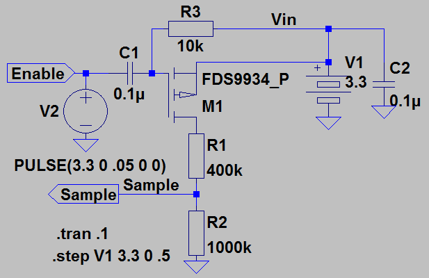
Sorry for the somewhat messy schematic. For those of you unfimiliar with LTspice, this is what the above is:
V1 is the battery to be measured. It's nominal voltage in this case is set to 3.3V. The voltage is stepped from 3.3V to 0 in 0.5 increments in the simulation.
For some noise suppression, it is decoupled with C2 but this makes little difference for the simulation I have made.
The battery voltage is fed through a PMOS FET (M1) before it enters the voltage divider. Below, I will use the term open for the FET when it is not conducting current and closed when it is.
The FET is by default tied in the open state using R3 as pull up to Vin. M1 is closed by grounding it's gate, or in this example by pulling Enable low from the MCU. V2 in this example serves as a crude simulation of the MCU grounding the Enable signal after 0.05s in the simulation time domain (simulation is executed for 0.1s).
The neat feature here is C1, which isolates the MCU output pin from the FET, thus preventing leakage through the MCU. When Enable goes low, M1 is closed momentarily, before C1 regains the charge from the pull from R3 and is opened once again. The value of C1 and R3 can be picked to suit the speed of the MCU (the MCU needs to take the sample before M1 opens).
When Enable is left floating, any charge pushed into C1 is fed back to Vin, and is thus "free".
This also allows the voltage divider to span the entire ADC range (depending on what ADC is used, internal references and such).Below is the resulting waveforms when using a Fairchild FDS9934 as FET (somewhat equivalent breadboard-friendly component could be this).
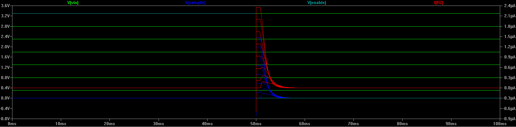
Note here the large span of V(sample) as well as the peak current at the largest voltage level (2.4uA). The current remains constant for a brief period of time (decided by C1 and R3) and then dissipates down to 0, even if Enable is kept low. The current can be reduced by manipulating R1 and R2, but the circuit becomes more sensitive to noise as the current used decreases (as can be seen for lower currents in the simulation, where capacitances in the FET start to make a difference.
-
I have run some simulations on a low-power solution using this setup:
Sorry for the somewhat messy schematic. For those of you unfimiliar with LTspice, this is what the above is:
V1 is the battery to be measured. It's nominal voltage in this case is set to 3.3V. The voltage is stepped from 3.3V to 0 in 0.5 increments in the simulation.
For some noise suppression, it is decoupled with C2 but this makes little difference for the simulation I have made.
The battery voltage is fed through a PMOS FET (M1) before it enters the voltage divider. Below, I will use the term open for the FET when it is not conducting current and closed when it is.
The FET is by default tied in the open state using R3 as pull up to Vin. M1 is closed by grounding it's gate, or in this example by pulling Enable low from the MCU. V2 in this example serves as a crude simulation of the MCU grounding the Enable signal after 0.05s in the simulation time domain (simulation is executed for 0.1s).
The neat feature here is C1, which isolates the MCU output pin from the FET, thus preventing leakage through the MCU. When Enable goes low, M1 is closed momentarily, before C1 regains the charge from the pull from R3 and is opened once again. The value of C1 and R3 can be picked to suit the speed of the MCU (the MCU needs to take the sample before M1 opens).
When Enable is left floating, any charge pushed into C1 is fed back to Vin, and is thus "free".
This also allows the voltage divider to span the entire ADC range (depending on what ADC is used, internal references and such).Below is the resulting waveforms when using a Fairchild FDS9934 as FET (somewhat equivalent breadboard-friendly component could be this).
Note here the large span of V(sample) as well as the peak current at the largest voltage level (2.4uA). The current remains constant for a brief period of time (decided by C1 and R3) and then dissipates down to 0, even if Enable is kept low. The current can be reduced by manipulating R1 and R2, but the circuit becomes more sensitive to noise as the current used decreases (as can be seen for lower currents in the simulation, where capacitances in the FET start to make a difference.
@Anticimex nice, thank you!
-
Thanks guys,
I'll happily elaborate more on the details, but perhaps it is best if you state some specific questions regarding parts of it that are difficult to comprehend. Imo, working with sensors should not require a degree in engineering, so nobody should "feel stupid" for asking questions :) -
Thanks guys,
I'll happily elaborate more on the details, but perhaps it is best if you state some specific questions regarding parts of it that are difficult to comprehend. Imo, working with sensors should not require a degree in engineering, so nobody should "feel stupid" for asking questions :)@Anticimex said:
Imo, working with sensors should not require a degree in engineering, so nobody should "feel stupid" for asking questions :)
When I have questions I will ask :)
But, like @hek, I need to let things 'sink in'.
And I really want to understand.
To be honest I have learned a lot (and spent a lot) since I stumbled upon MySensors.
Wonderful new hobby!
Hello! It looks like you're interested in this conversation, but you don't have an account yet.
Getting fed up of having to scroll through the same posts each visit? When you register for an account, you'll always come back to exactly where you were before, and choose to be notified of new replies (either via email, or push notification). You'll also be able to save bookmarks and upvote posts to show your appreciation to other community members.
With your input, this post could be even better 💗
Register Login