Which are the *best* NRF24L01+ modules?
-
If worse comes to worst, I'll just move ahead using blob modules. Who knows what they are, but could it be that they're actually better than genuine Nordic NRF24L01+'s?
-
OK, for easy testing, I just now ordered some socket adapters:
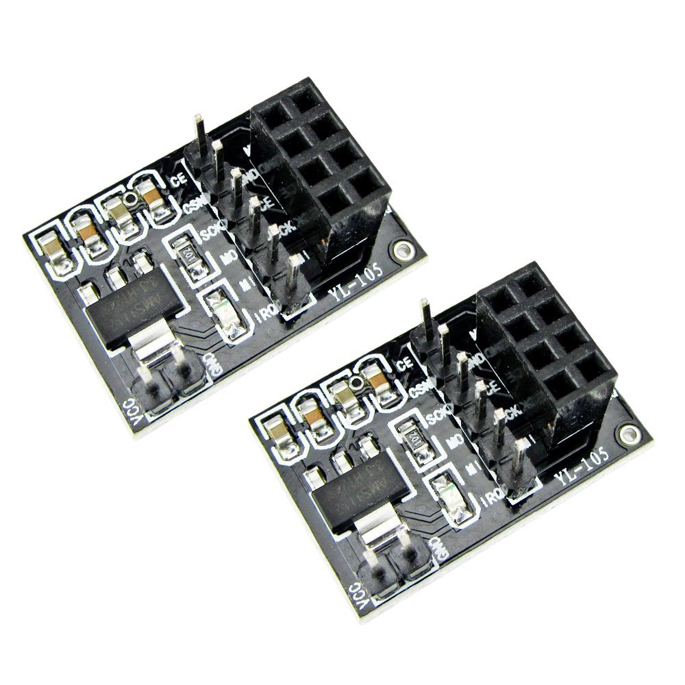
and should receive them on Tuesday. Also, instead of RFToys, I'll try driving them from Arduino Mega2560's. Does anyone here have experience to know whether the socket adapters will supply sufficient juice? I would hope so, as it would seem to be its primary function, but if anyone knows for sure one way or the other, please post.
Meanwhile, I may try powering the modules using bench power supplies.
@NeverDie do you use a good power supply?
-
@NeverDie do you use a good power supply?
@Moshe-Livne said:
@NeverDie do you use a good power supply?
Define "good". :blush:
I've been powering through nominal 5v USB, either through a computer's USB port for the master trasceiver (so, typically 500ma peak current) or through a typical USB charger module (typically nominal 5v 1amp or better peak current) for the slave echo transceiver. I'm not sure how the RFToy steps it down to 3.3v, or what the peak current available is on an RFToy at 3.3v. It seems good enough for the blob modules, so I (perhaps erroneously) assumed it should be good enough for the alleged NRF24L01+ modules. I'm aware some people have been getting better results using 10uF capacitors. In one of the threads it was claimed that only the fake NRF24L01_modules benefit from using capacitors(?), so I haven't rushed to embrace using capacitors. However, if you think it advisable, I could certainly try that.
-
@Moshe-Livne said:
@NeverDie do you use a good power supply?
Define "good". :blush:
I've been powering through nominal 5v USB, either through a computer's USB port for the master trasceiver (so, typically 500ma peak current) or through a typical USB charger module (typically nominal 5v 1amp or better peak current) for the slave echo transceiver. I'm not sure how the RFToy steps it down to 3.3v, or what the peak current available is on an RFToy at 3.3v. It seems good enough for the blob modules, so I (perhaps erroneously) assumed it should be good enough for the alleged NRF24L01+ modules. I'm aware some people have been getting better results using 10uF capacitors. In one of the threads it was claimed that only the fake NRF24L01_modules benefit from using capacitors(?), so I haven't rushed to embrace using capacitors. However, if you think it advisable, I could certainly try that.
@NeverDie I do not use capacitors but I have noticed that the quality of the power supply is important but USB from a computer should have very little noise so that is not the reason.
If you happen to have capacitors, would be interesting to see how they effect the results.
@hek (or anyone else who knows what they are doing), as this seems to be a universal problem, why don't you start a github sketch with simple regression results that will evolve with time? we can also start a google drive spreadsheet to collect the results so we can record who we bought it from, include a photo and the results. Although the Chinese merchants can be fickle with they supply chain, at least on aliexpress you can verify beforehand with them that you are getting specific things and if you get something else you just don't pay. It is possible to establish good and reliable supply with them if they see that it brings them consistent returns and rating - I have done that with components for my LED lights. But we need a simple way of telling what we get.... -
I looked just now at section 10.4 of the Nordic Semiconductor spec sheet for the NRF24L01+, and if I'm reading this right, it does make specific recommendations that may be worth repeating here:
"The nRF24L01 DC supply voltage should be decoupled as close as possible to the VDD pins with high performance
RF capacitors, see Table 26. on page 69. It is preferable to mount a large surface mount capacitor
(for example, 4.7μF ceramic) in parallel with the smaller value capacitors. The nRF24L01 supply
voltage should be filtered and routed separately from the supply voltages of any digital circuitry."I'm not sure if that's advocating the use of a large capacitor (such as a 4.7uF), or merely stating that if a large surface mount capacitor is used, then it's preferable it be mounted in parallel. I think it may be advocating. Can anyone here resolve the ambiguity? Would a 10uF capacitor commonly added by some people be relevant to this, or would it literally need to be a surface-mount component to qualify? Also, since it did specifically mention ceramic, is it important that it be ceramic rather than some other type? And if so, what type of ceramic capacitor would be best?
Does supplying 3.3v from a voltage regulator right near the module, as in the adapter module I picture above, help provide a supply voltage that's separately filtered and routed, in part by putting it close to the NRF chip? I ask because it also says "Full swing digital data or control signals should not be routed close to the crystal or the power supply lines."
-
I looked just now at section 10.4 of the Nordic Semiconductor spec sheet for the NRF24L01+, and if I'm reading this right, it does make specific recommendations that may be worth repeating here:
"The nRF24L01 DC supply voltage should be decoupled as close as possible to the VDD pins with high performance
RF capacitors, see Table 26. on page 69. It is preferable to mount a large surface mount capacitor
(for example, 4.7μF ceramic) in parallel with the smaller value capacitors. The nRF24L01 supply
voltage should be filtered and routed separately from the supply voltages of any digital circuitry."I'm not sure if that's advocating the use of a large capacitor (such as a 4.7uF), or merely stating that if a large surface mount capacitor is used, then it's preferable it be mounted in parallel. I think it may be advocating. Can anyone here resolve the ambiguity? Would a 10uF capacitor commonly added by some people be relevant to this, or would it literally need to be a surface-mount component to qualify? Also, since it did specifically mention ceramic, is it important that it be ceramic rather than some other type? And if so, what type of ceramic capacitor would be best?
Does supplying 3.3v from a voltage regulator right near the module, as in the adapter module I picture above, help provide a supply voltage that's separately filtered and routed, in part by putting it close to the NRF chip? I ask because it also says "Full swing digital data or control signals should not be routed close to the crystal or the power supply lines."
@NeverDie No expert so just regurgitating what I read here on other threads:
The capacitor serves two purposes:- give the module extra juice while transmitting
- clean and smooth the noise on the power
for (1), electrolite capacitor is good enough. for (2), people here said that ceramic is much better as it has all sorts of good qualities that has 3 or 4 letters acronyms. (not an expert!)
the capacitor needs to be mounted as closely to the module otherwise the legs serves as antenna for interference or something.
if you have a good power supply that produce good, clean 3.3v (a battery is a good example), connecting it directly to the nrf vcc is better than taking the 3v3 from the arduino.
-
@NeverDie No expert so just regurgitating what I read here on other threads:
The capacitor serves two purposes:- give the module extra juice while transmitting
- clean and smooth the noise on the power
for (1), electrolite capacitor is good enough. for (2), people here said that ceramic is much better as it has all sorts of good qualities that has 3 or 4 letters acronyms. (not an expert!)
the capacitor needs to be mounted as closely to the module otherwise the legs serves as antenna for interference or something.
if you have a good power supply that produce good, clean 3.3v (a battery is a good example), connecting it directly to the nrf vcc is better than taking the 3v3 from the arduino.
@Moshe-Livne said:
@NeverDie No expert so just regurgitating what I read here on other threads:
The capacitor serves two purposes:- give the module extra juice while transmitting
- clean and smooth the noise on the power
for (1), electrolite capacitor is good enough. for (2), people here said that ceramic is much better as it has all sorts of good qualities that has 3 or 4 letters acronyms. (not an expert!)
the capacitor needs to be mounted as closely to the module otherwise the legs serves as antenna for interference or something.
if you have a good power supply that produce good, clean 3.3v (a battery is a good example), connecting it directly to the nrf vcc is better than taking the 3v3 from the arduino.
Thanks for the good info. . Since it's better for both MySensors and Itead to have a good working relationship where such matters can be quickly resolved, for now I'm going to hold off on soldering in the event Itead (the manufacturer) wants to inspect the modules I received in the same condition that I received them. Hopefully Hek will soon post an update from Itead regarding whether the modules are genuine or not. In addition to what has already been discussed, the packaging does not exactly match what Itead has shown on their website, judging from a post by Sparkman in a different thread related to this.
I ordered from one of Itead's officially designated distributors, so I hope Itead stands behind their product and what was delivered. I really do hope I haven't been Shanghaied, but if that's how it shakes out, at least I limited the damage by purchasing only 3 modules to begin with rather than the larger number I'll ultimately be ordering.
-
-
This is Jerry from ITEAD.
The Module we sell is original.
Can you provide me your contact information?
We will ask Nordic FAE in your country to contact you and test the module together with you.
Just post the test result publicly on the forum.@jerry said:
This is Jerry from ITEAD.
The Module we sell is original.
Can you provide me your contact information?
We will ask Nordic FAE in your country to contact you and test the module together with you.
Just post the test result publicly on the forum.Hi Jerry,
Thanks for your fast response to my post.
Geographically I'm in Austin, Texas (USA). I don't see a way to PM you with my email address, as it doesn't look as though this forum supports private messaging. However, if you like I can post a temporary alias email address here to facilitate our initial exchange of contact info. Or, if you prefer to post your email address, I can email you from my email address, and thereby connect that way. Would that work?
Yes, I'd be happy to publish the test results on the forum. The more transparency, the better for everyone.
-
@jerry said:
This is Jerry from ITEAD.
The Module we sell is original.
Can you provide me your contact information?
We will ask Nordic FAE in your country to contact you and test the module together with you.
Just post the test result publicly on the forum.Hi Jerry,
Thanks for your fast response to my post.
Geographically I'm in Austin, Texas (USA). I don't see a way to PM you with my email address, as it doesn't look as though this forum supports private messaging. However, if you like I can post a temporary alias email address here to facilitate our initial exchange of contact info. Or, if you prefer to post your email address, I can email you from my email address, and thereby connect that way. Would that work?
Yes, I'd be happy to publish the test results on the forum. The more transparency, the better for everyone.
-
@NeverDie said:
I don't see a way to PM you with my email address, as it doesn't look as though this forum supports private messaging.
Just click on a avatar and press the "Chat" button. The messages is stored just like old-style PM.
@hek said:
@NeverDie said:
I don't see a way to PM you with my email address, as it doesn't look as though this forum supports private messaging.
Just click on a avatar and press the "Chat" button. The messages is stored just like old-style PM.
Thanks for explaining that. As a result, I just sent Jerry my contact info that way.
-
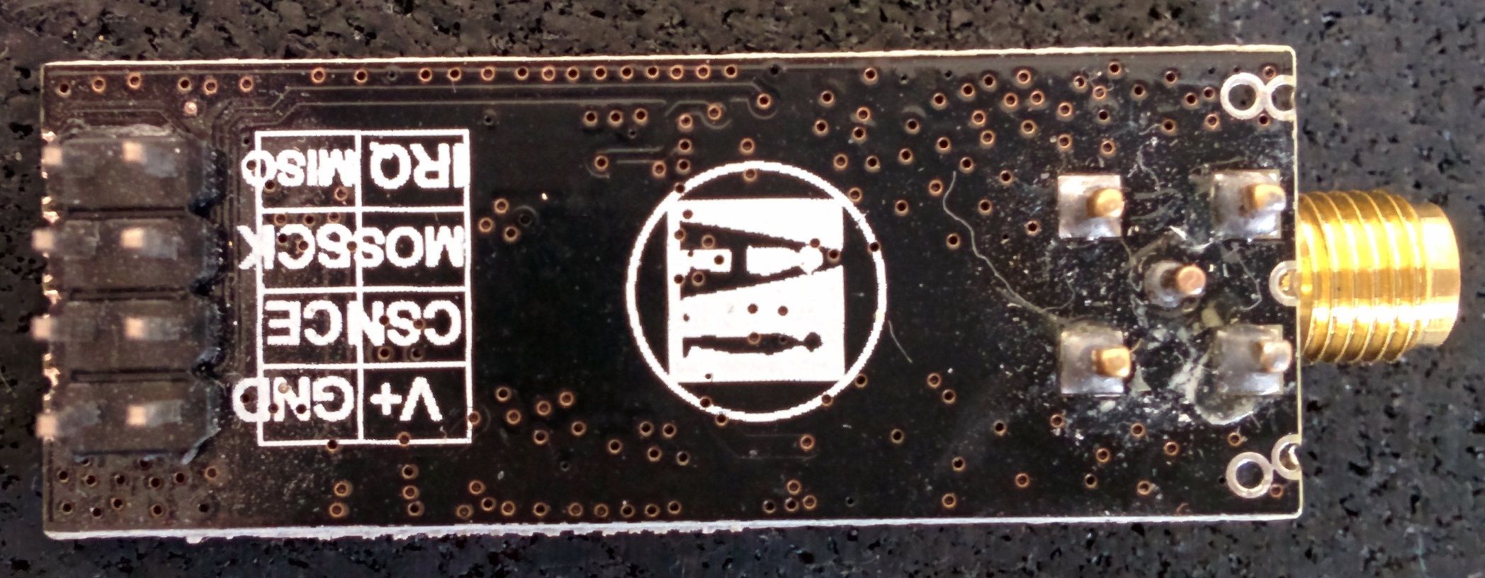
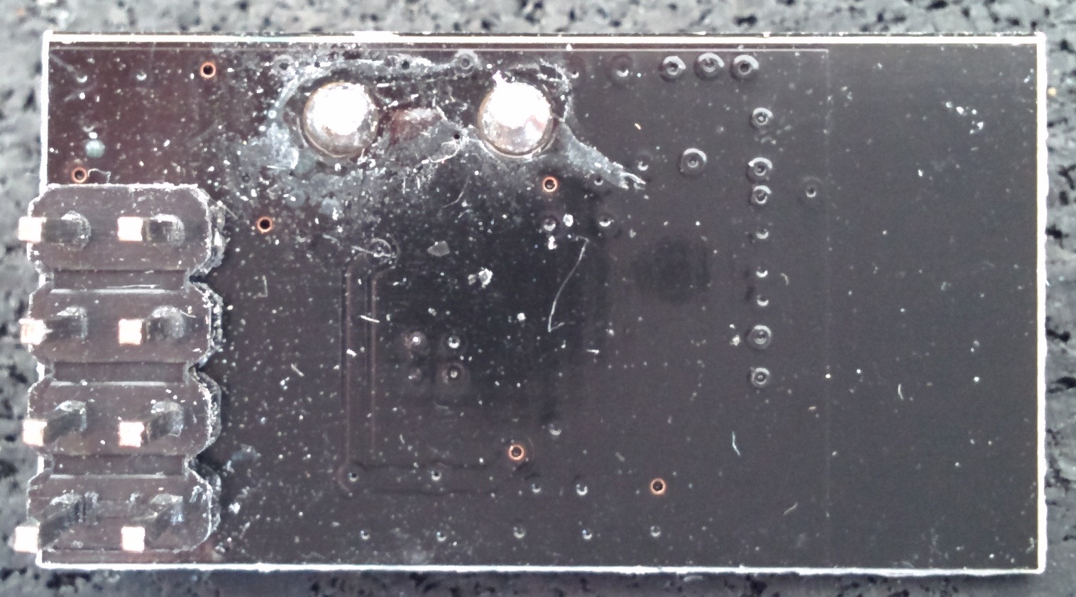
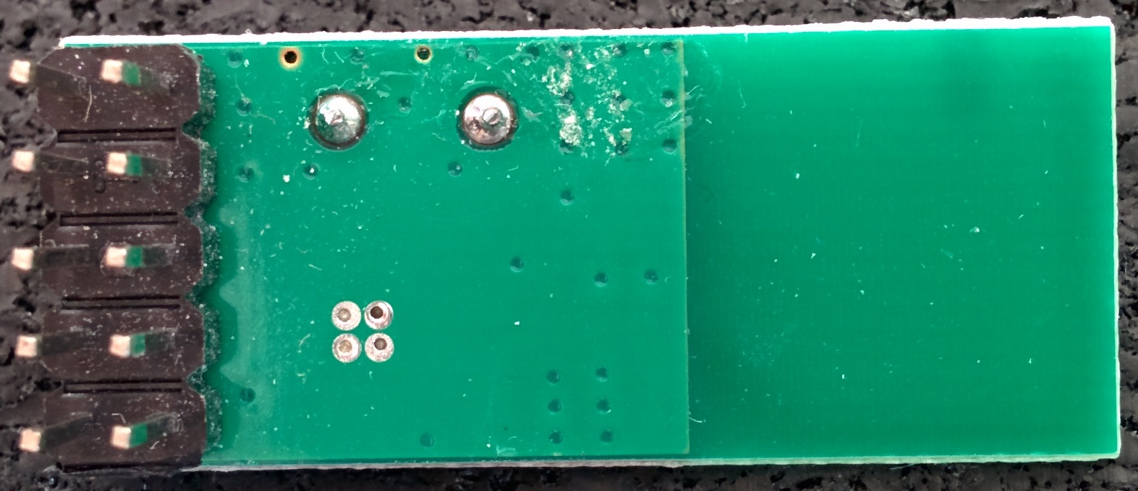
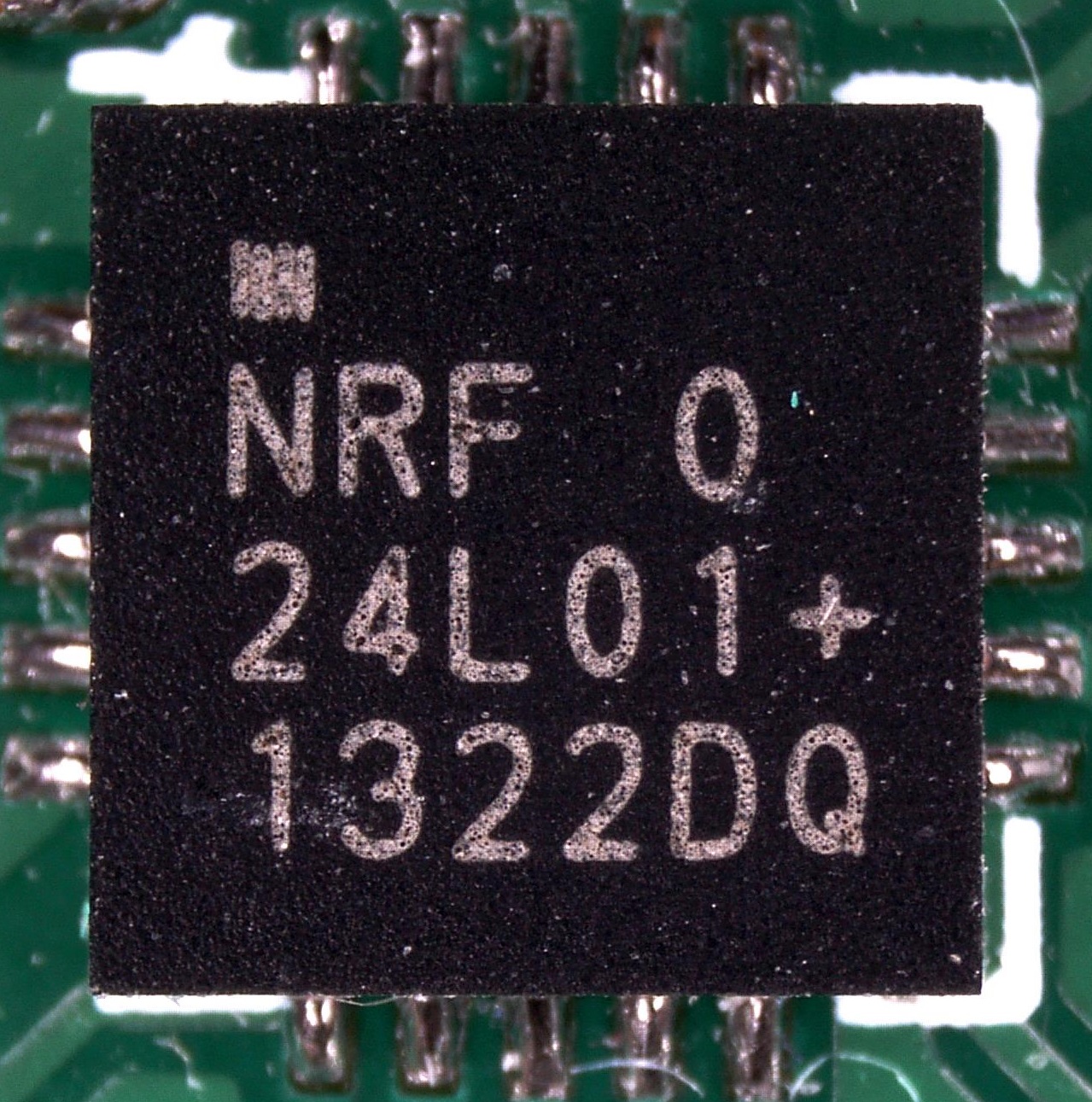
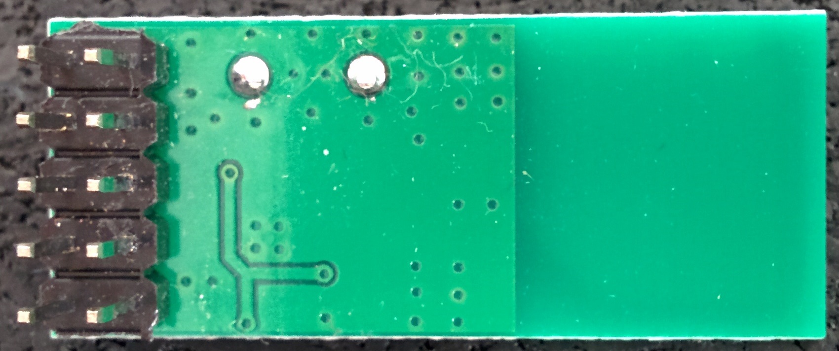
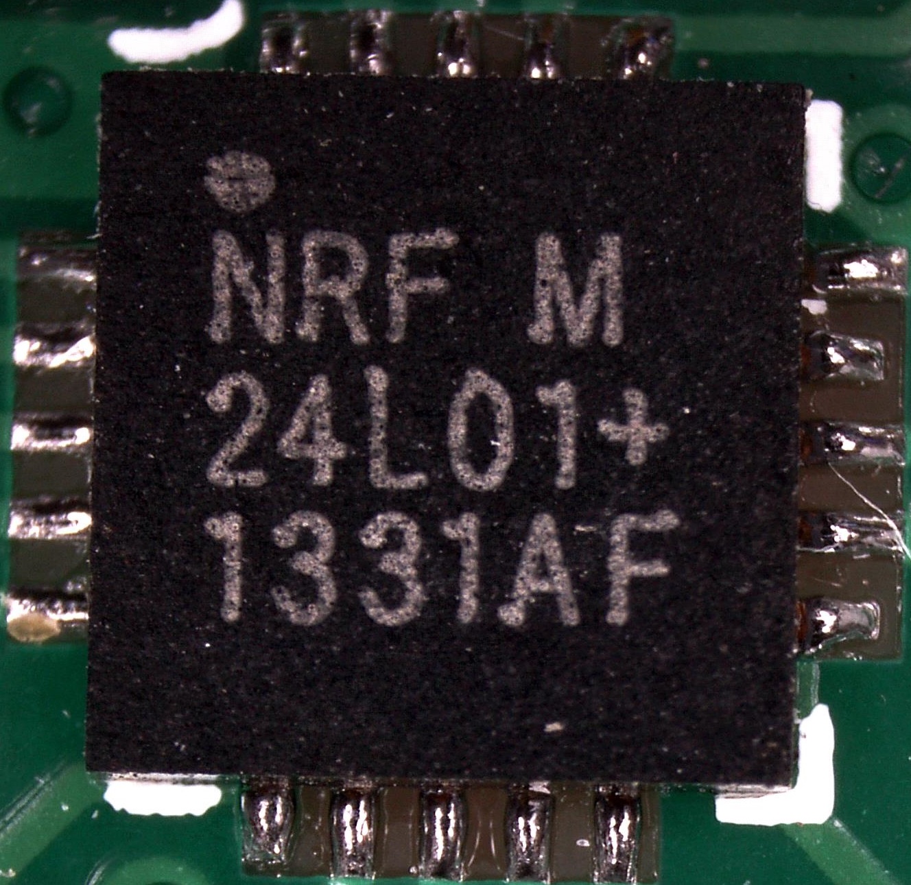
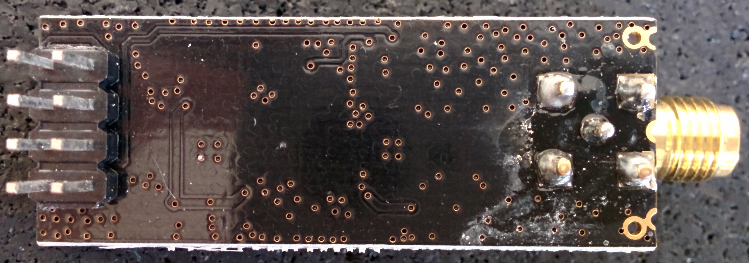
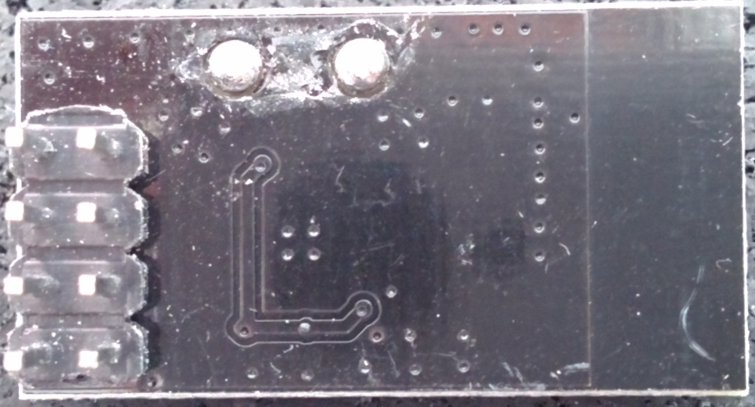
An overview of the module I have lying around (origin is unclear, as I don't really keep track of where they come from)
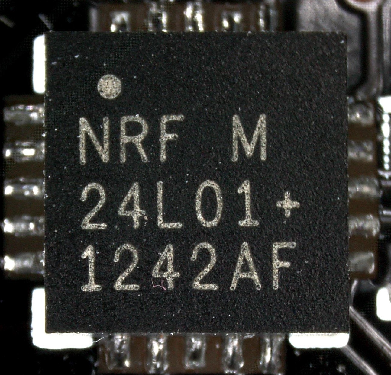
The chip close-ups were taken using a microscope, so they have far higher resolution then shown in the table (right-click & show image to view at native resolution) .Datecode YYWWLL Module top Module bottom Closeup Fake/Genuine 0830AE 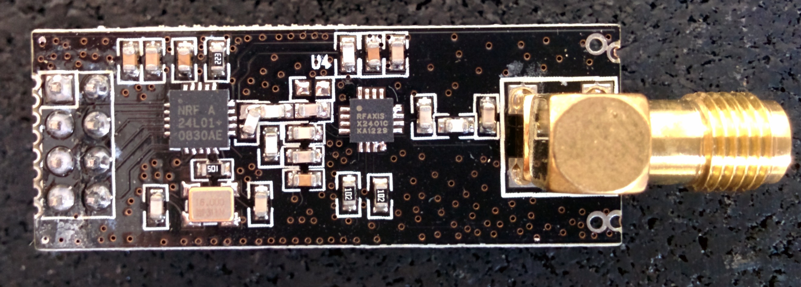
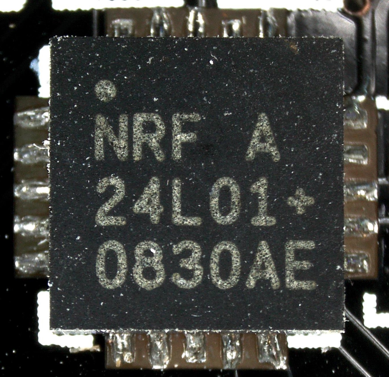
Genuine? Datecode 0830 indicates production wk30 2008. nRF24L01+ was launched in 2008 1242AF 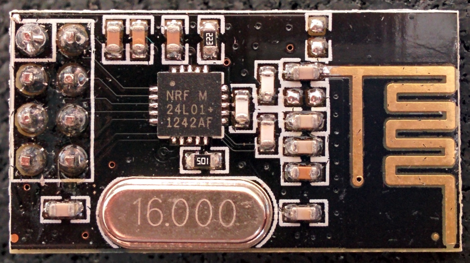
Known counterfeit, according to this 1322DQ 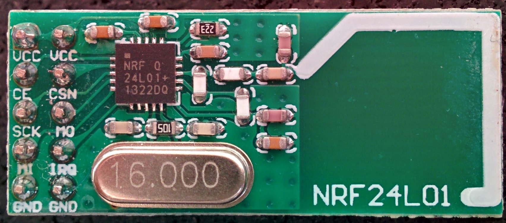
1331AF 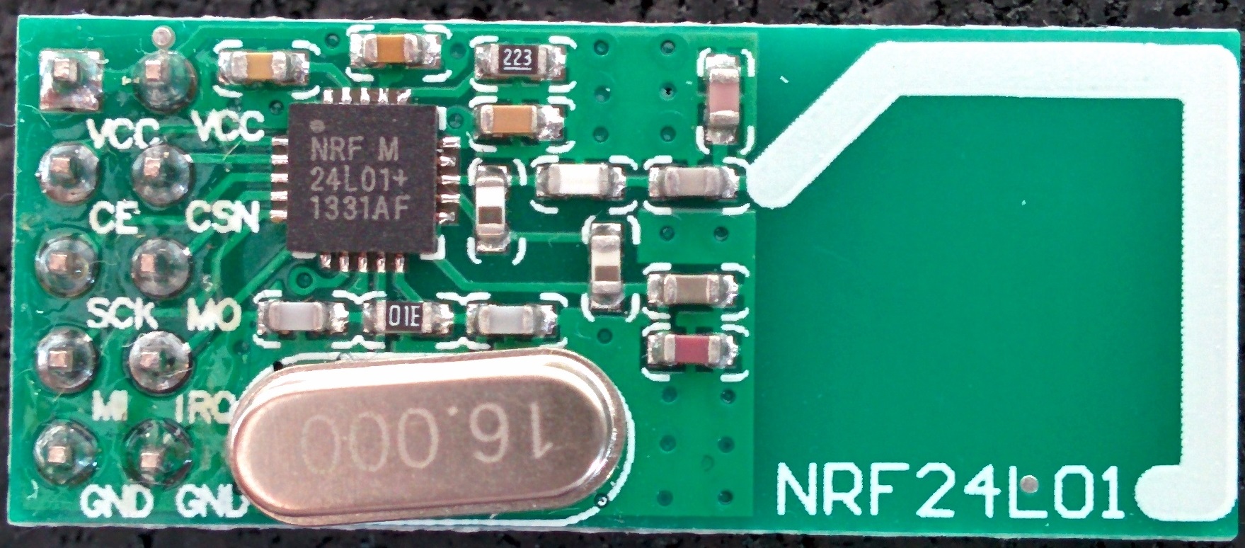
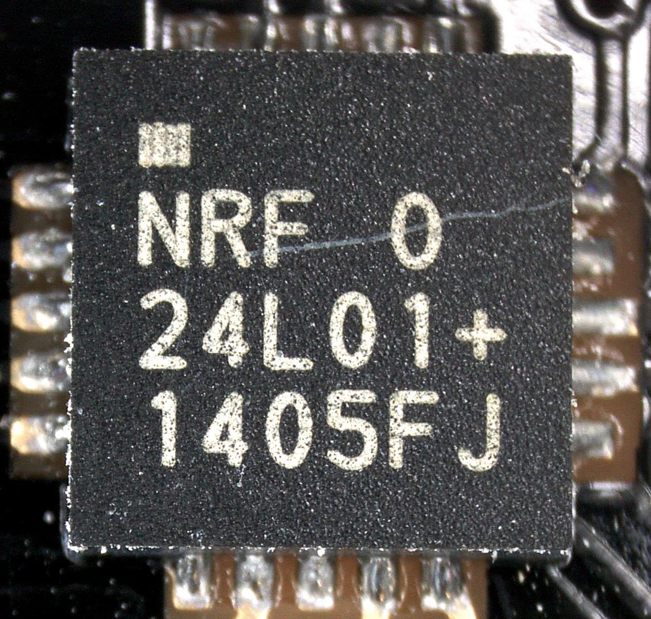
Known counterfeit, according to this 1405FJ 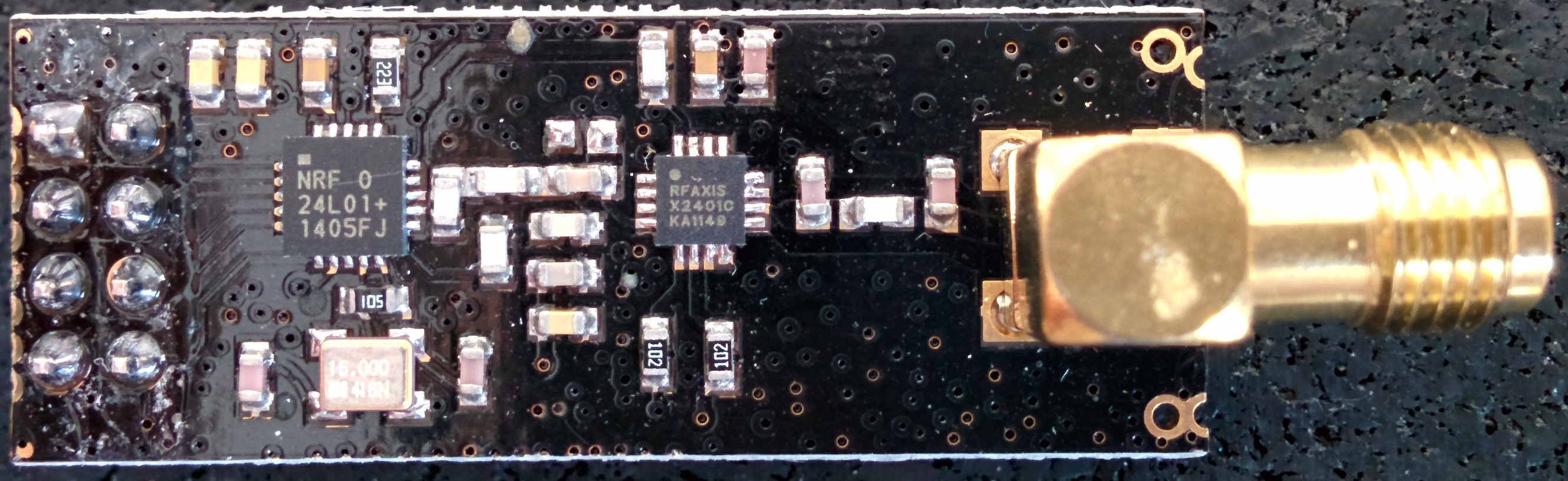
1408AF 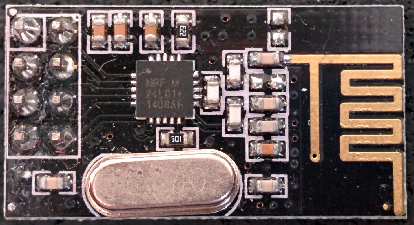
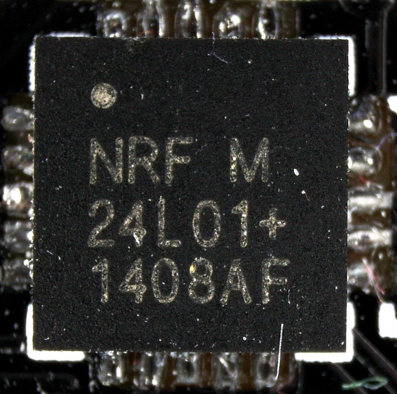
Probably fake (identical to left one bottom of the page -
@NeverDie I do not use capacitors but I have noticed that the quality of the power supply is important but USB from a computer should have very little noise so that is not the reason.
If you happen to have capacitors, would be interesting to see how they effect the results.
@hek (or anyone else who knows what they are doing), as this seems to be a universal problem, why don't you start a github sketch with simple regression results that will evolve with time? we can also start a google drive spreadsheet to collect the results so we can record who we bought it from, include a photo and the results. Although the Chinese merchants can be fickle with they supply chain, at least on aliexpress you can verify beforehand with them that you are getting specific things and if you get something else you just don't pay. It is possible to establish good and reliable supply with them if they see that it brings them consistent returns and rating - I have done that with components for my LED lights. But we need a simple way of telling what we get....@Moshe-Livne said:
why don't you start a github sketch with simple regression results that will evolve with time?
I'm thinking about a simple sketch, based of the nRF24 Sniffer's code, which connects two radios and checks on air how a radio communicates. This should allow detecting the inverted NO_ACK bit (see Jay Tyzzer's comment here) to immediately quilify a module as fake when detected.
Of course this doesn't mean it's genuine when doesn't have the bit inverted, but the sketch could also dump register settings to be able to detect a pattern. -
Great pictures! What microscope are you using?
I can't see anyone having the hole in the +-sign...
-
Great pictures! What microscope are you using?
I can't see anyone having the hole in the +-sign...
-
@Moshe-Livne said:
why don't you start a github sketch with simple regression results that will evolve with time?
I'm thinking about a simple sketch, based of the nRF24 Sniffer's code, which connects two radios and checks on air how a radio communicates. This should allow detecting the inverted NO_ACK bit (see Jay Tyzzer's comment here) to immediately quilify a module as fake when detected.
Of course this doesn't mean it's genuine when doesn't have the bit inverted, but the sketch could also dump register settings to be able to detect a pattern.@Yveaux wonderful! Even if fake, ones with correct ack bit will probably work better so its a step in the right direction
-
An overview of the module I have lying around (origin is unclear, as I don't really keep track of where they come from)
The chip close-ups were taken using a microscope, so they have far higher resolution then shown in the table (right-click & show image to view at native resolution) .Datecode YYWWLL Module top Module bottom Closeup Fake/Genuine 0830AE Genuine? Datecode 0830 indicates production wk30 2008. nRF24L01+ was launched in 2008 1242AF Known counterfeit, according to this 1322DQ 1331AF Known counterfeit, according to this 1405FJ 1408AF Probably fake (identical to left one bottom of the page @Yveaux said:
An overview of the module I have lying around (origin is unclear, as I don't really keep track of where they come from)
The chip close-ups were taken using a microscope, so they have far higher resolution then shown in the table (right-click & show image to view at native resolution) .Datecode YYWWLL Module top Module bottom Closeup Fake/Genuine 0830AE Genuine? Datecode 0830 indicates production wk30 2008. nRF24L01+ was launched in 2008 FWIW, the 0830AE date code is only a little earlier (4 weeks?) than the 0834AF datecode on the chip above in Hek's post where Hek alleges the module is genuine.
-
@Yveaux said:
I really needed it to hand-solder those QFN's ;-)
How hard would it be to desolder a bogus NRF chip and then solder a known good NRF24L01+ (purchased either directly from Nordic, if Nordic does that, or else from a trusted distributor like Digikey) in its place? Perhaps in this way the modules can be given a second life of sorts.
Hello! It looks like you're interested in this conversation, but you don't have an account yet.
Getting fed up of having to scroll through the same posts each visit? When you register for an account, you'll always come back to exactly where you were before, and choose to be notified of new replies (either via email, or push notification). You'll also be able to save bookmarks and upvote posts to show your appreciation to other community members.
With your input, this post could be even better 💗
Register Login