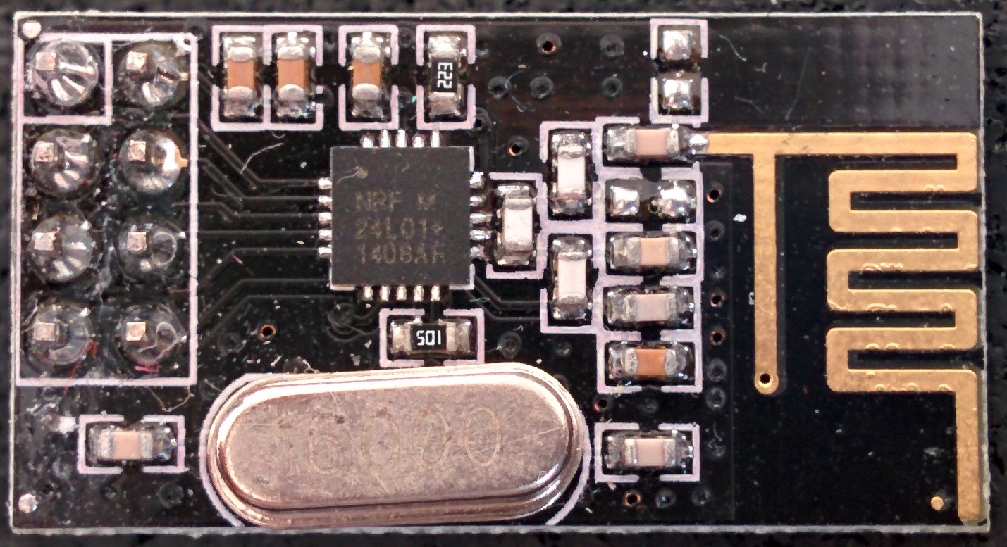
Which are the *best* NRF24L01+ modules?


  • Hero Member

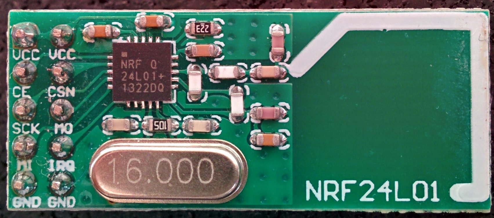
    For instance, in this type any good?
    10pin.JPG

    It has 10 pins instead of 8, but the two extra pins are just redundant Ground and Vcc pins. Is there good reason for that, or is it pointless? The shape of the antenna is different as well.

    I already have a couple modules with the black epoxy blob on it that turns out to be, at best, an NRF24L01 (no plus), or possibly a clone. I know that because it won't do 250kbps using the exact same code that I can make this common module do 250kbps:
    common.jpg

    Amazingly, though, the epoxy blob module does a much better job than the common module (pictured directly above) at 1mbps and 2mbps, so maybe the common module is a flawed fake as well? BTW, I did read the thread on fakes, which was helpful.

    Anyhow, I want to know what the best module would be to buy. Anyone know or have an opinion?


  • Hero Member

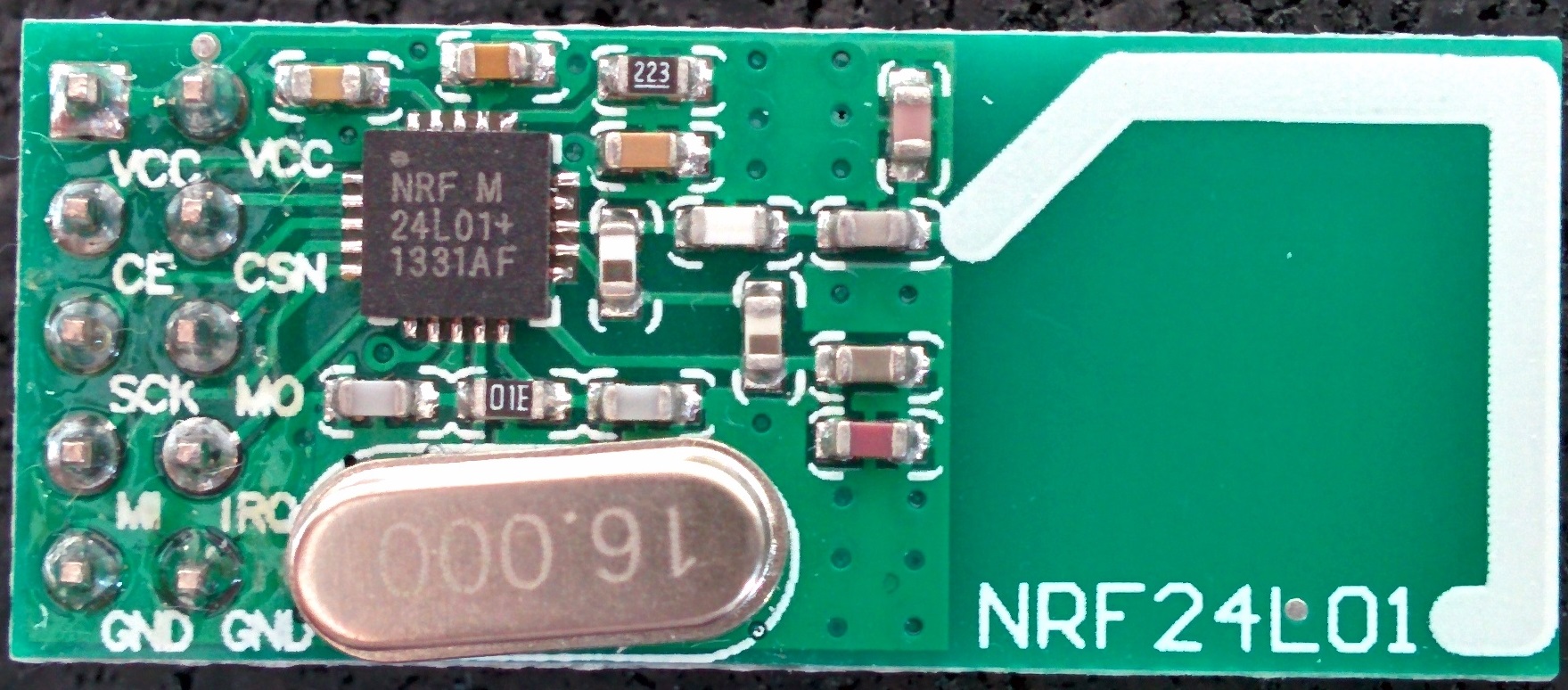
    I just now photographed side-by-side the two types of modules that I have, You can click through to get an even better view of the details:

    nrf24.jpg

    The one on the left is what I'm referring to above as the "epoxy blob" module. The one on the right I purchased from Addicore in April 2014 through Amazon.

    I've sent over 10 million packets through a pair of the epoxy blob modules at 2mbps (well, at least according to the settings it was 2mbps), and with both modules sitting across from one another about 20 feet apart in the same room I had absolutely zero packet loss. In contrast to that, a pair of the Addicore modules, also set to 2mbps, appear to have packet losses no matter how far apart they are in the exact same room. On the other hand, the Addicore modules can do 250kbps, whereas the epoxy blob modules can't. Perhaps there are other differences also.

    Plainly, the epoxy blob module is missing a lot of the surface mount components visible on the Addicore module, which is surprising given that the epoxy blob module actually seems to perform better at the 1Mbps and 2Mbps data rates than the Addicore module!

    Hmmmm.... According to a post here, the 1242AF marking on the NRF24L01+ chip on the Addicore module in my photograph above indicates it to be a known counterfeit. That would certainly explain a lot!


  • Hero Member

    it looks like the blob-one is missing some SMD components. 😉
    Are you able to measure the performance in long-distance (or maybe with walls in between)? The 250kbps should perform better --- in theory....


  • Hero Member

    @rvendrame said:

    it looks like the blob-one is missing some SMD components. 😉
    Are you able to measure the performance in long-distance (or maybe with walls in between)? The 250kbps should perform better --- in theory....

    Yes, I've done that test already using a pair of Addicore modules. For that test setup, I got 30% packet loss at 250kbps, 87% packet loss at 1mbps, and 100% packet loss at 2mbps (not even a single packet got through). For the packets that did survive the round trip, the average round trip travel times (using an 8Mhz Arduino to echo it back) were 2.8ms for the 250kbps datarate and 3.5ms for the 1Mbps datarate. I'm not sure why the roundtrip time was less at the 250kbps datarate, unless ithe round trip times reflect a lot of retries that the modules are doing without my specifically directing it. The maximum number of retries would have been whatever the default is, because I never set it (though perhaps the Mirf library did so without me being aware of it).

    It was when I tried doing that test with a pair of blob modules that I realized they couldn't be using genuine NRF24L01+ chips, because they lacked the 250kbps capability..


  • Admin

    You should also compare the power consumption. From what I have read the genuine Nordic module has much better characteristics.


  • Hero Member


  • Hero Member

    I ordered 3 NRF24L01+ modules from an Itead distributor named EpicTinker. The units arrived each in their own individual box:

    boxes.jpg

    Inside the box was this:

    inside.jpg

    Inside the sealed packaging was this module:

    module.jpg

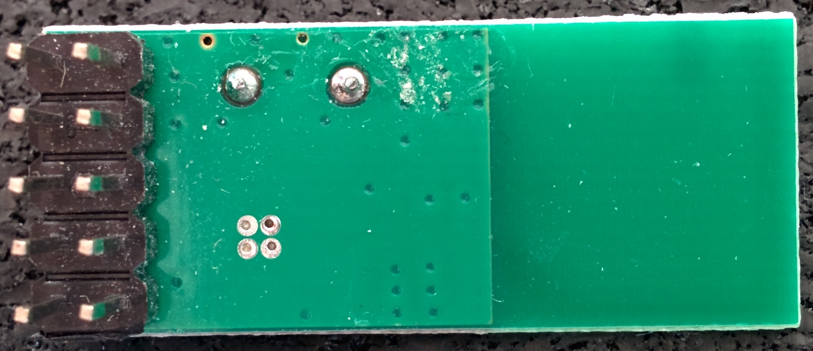
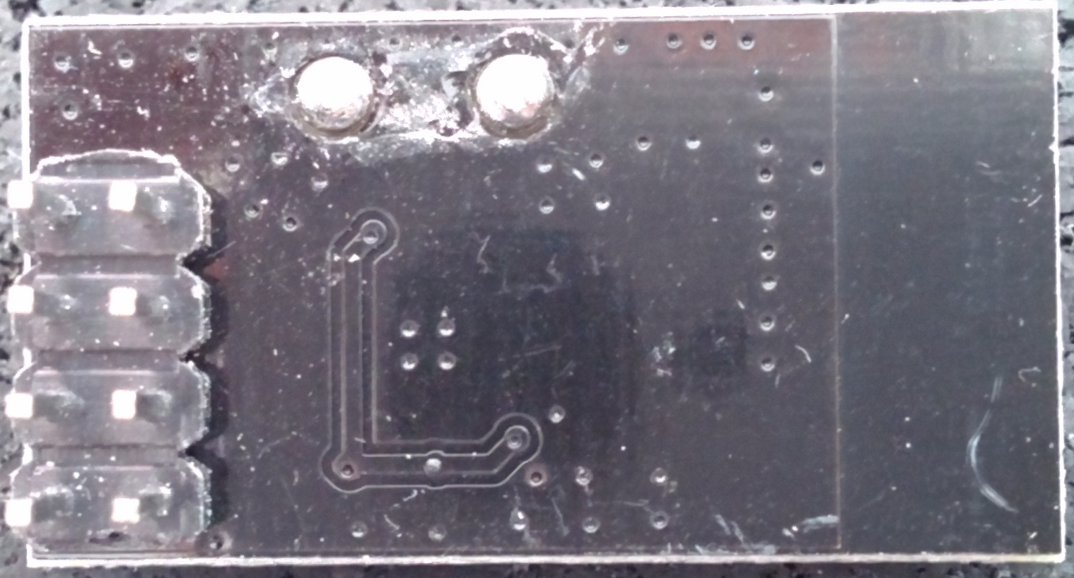
    Here's the back of the same module:

    back.jpg

    I ran a ping-pong test, as I had done with other modules, and at 1mbps in the same location, after sending 88,000 packets, the packet loss rate was 99.8%, and the average round trip time was 3.75ms.

    So, a worse rate of packet loss and average worse round-trip time than with the addicore's I described above.

    So, is it a bogus chip, or is the module layout bad, or....? Does the packaging match what others are receiving from itead directly?


  • Mod

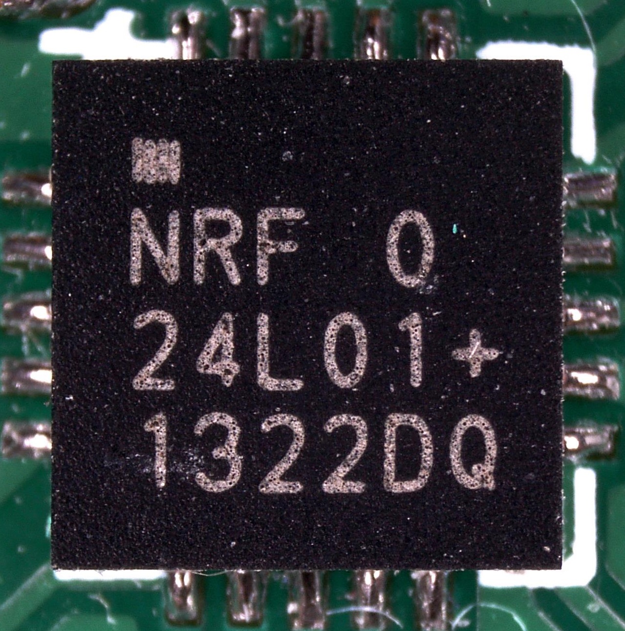
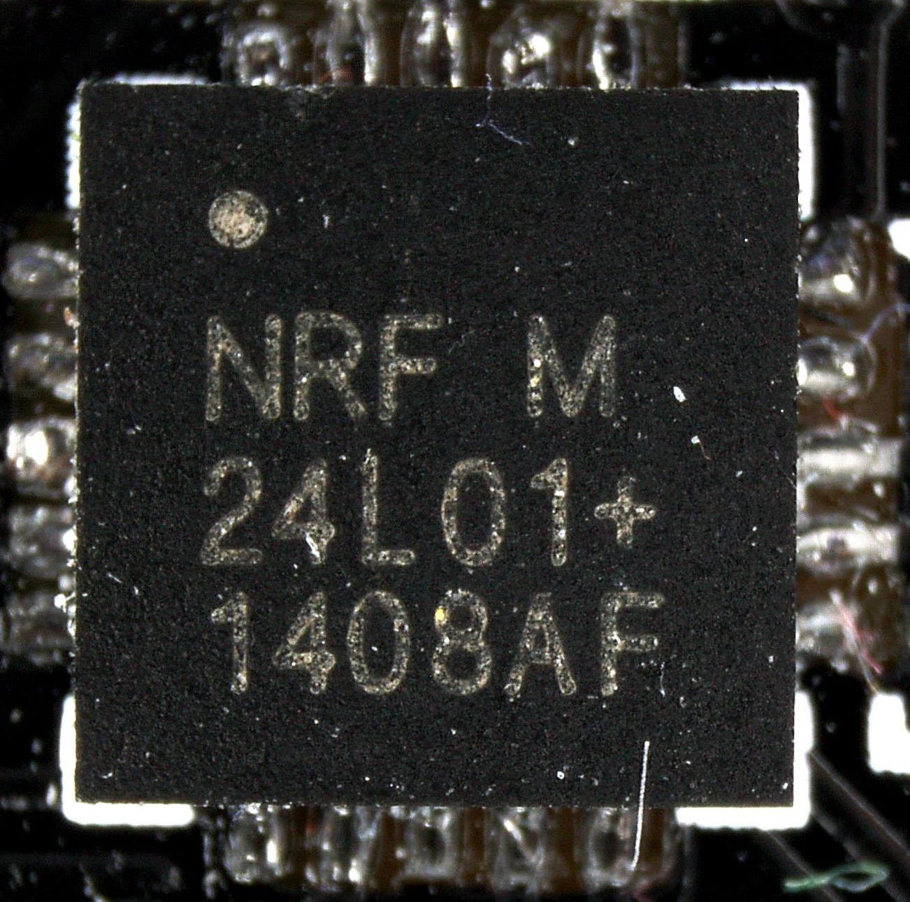
    @NeverDie Probably the best indication of real vs. counterfeit is the laser marking on the IC:

    Nordic-NRF24L01P-cmp.jpg
    source

    One on the right is genuine.
    Especially the '+' sign is different on both markings -- it has a 'hole' in the center on the genuine one.

    Yours seems to be solid too...

    Possibly it would help if we start composing a list of all versions encountered 'in the wild', including register dumps and fotos and try to find a common identification for genuine/fake ones.


  • Hero Member

    Yes, module from EpicTinker looks relatively solid in the '+', and the dot is visibly hollow:

    zoom.jpg

    So, does that mean it's a fake?

    Also, I notice that in the two chips you compare side-by-side, the "1" font is definitely different.


  • Admin

    I've asked for a comment from Itead.


  • Hero Member

    Also, I notice that on your genuine board, the discrete component below the chip has the value 105 (or is it 501?), whereas on mine it says 01E. That's different. Is there such a thing as an 01E?


  • Hero Member

    @hek said:

    I've asked for a comment from Itead.

    Thanks! Please post when you hear back.


  • Mod

    @NeverDie 01E is one meg ohm (table) which is the same as 105.
    Sharp notice regarding the different 1 on both IC's! 👍
    I cannot say that yours are genuine or not. That's why I suggest we join forces and start collecting data to discover some patterns to distinguish fakes from genuine!


  • Admin

    This is a genuine Nordic module. Not easy to see the hole in the cross.
    nordic.jpg

    Here is some misc module I bought from ebay:
    miccmodule.jpg

    Here is an amplified module of mine.
    ampmodule.jpg


  • Hero Member

    @hek said:

    This is a genuine Nordic module. Not easy to see the hole in the cross.
    nordic.jpg

    Here is some misc module I bought from ebay:
    miccmodule.jpg

    Here is an amplified module of mine.
    ampmodule.jpg

    Have you observed any difference in the performance of the three different modules that you have? The module in the middle photo has the "1" font discrepancy noted above.


  • Admin

    @NeverDie

    No, haven't done any scientific regression tests on them.


  • Hero Member

    @Yveaux said:

    That's why I suggest we join forces and start collecting data to discover some patterns to distinguish fakes from genuine!

    I 100% agree. That's why I'm posting as much info as I can. I hope others will do the same, as it is in our common interest.

    In my testing to date, at 1Mbps the blob modules vastly outperform the allegedly Itead modules. The question is: what can I attribute that to? I won't ever be buying anything more from Itead or any of its distributors until after this gets resolved.


  • Hero Member

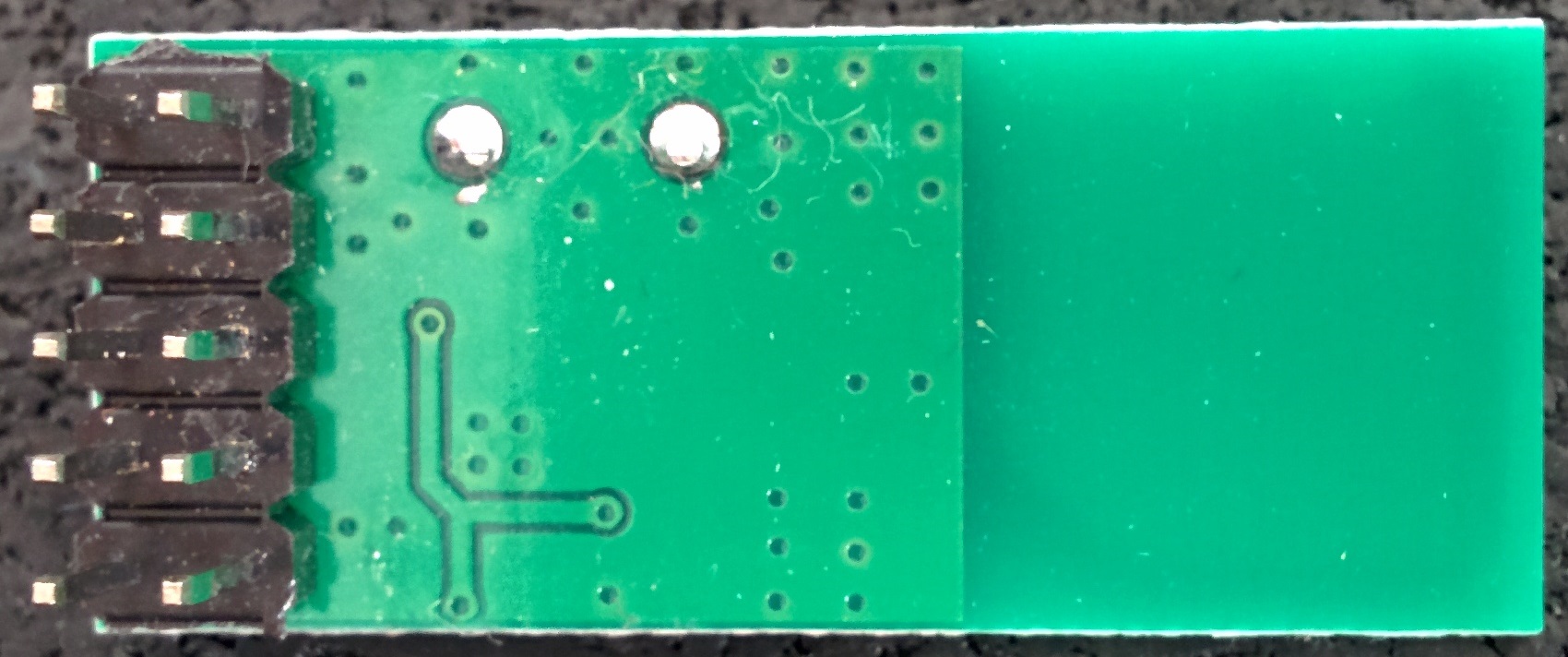
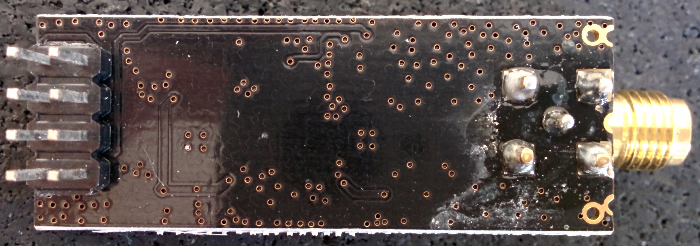
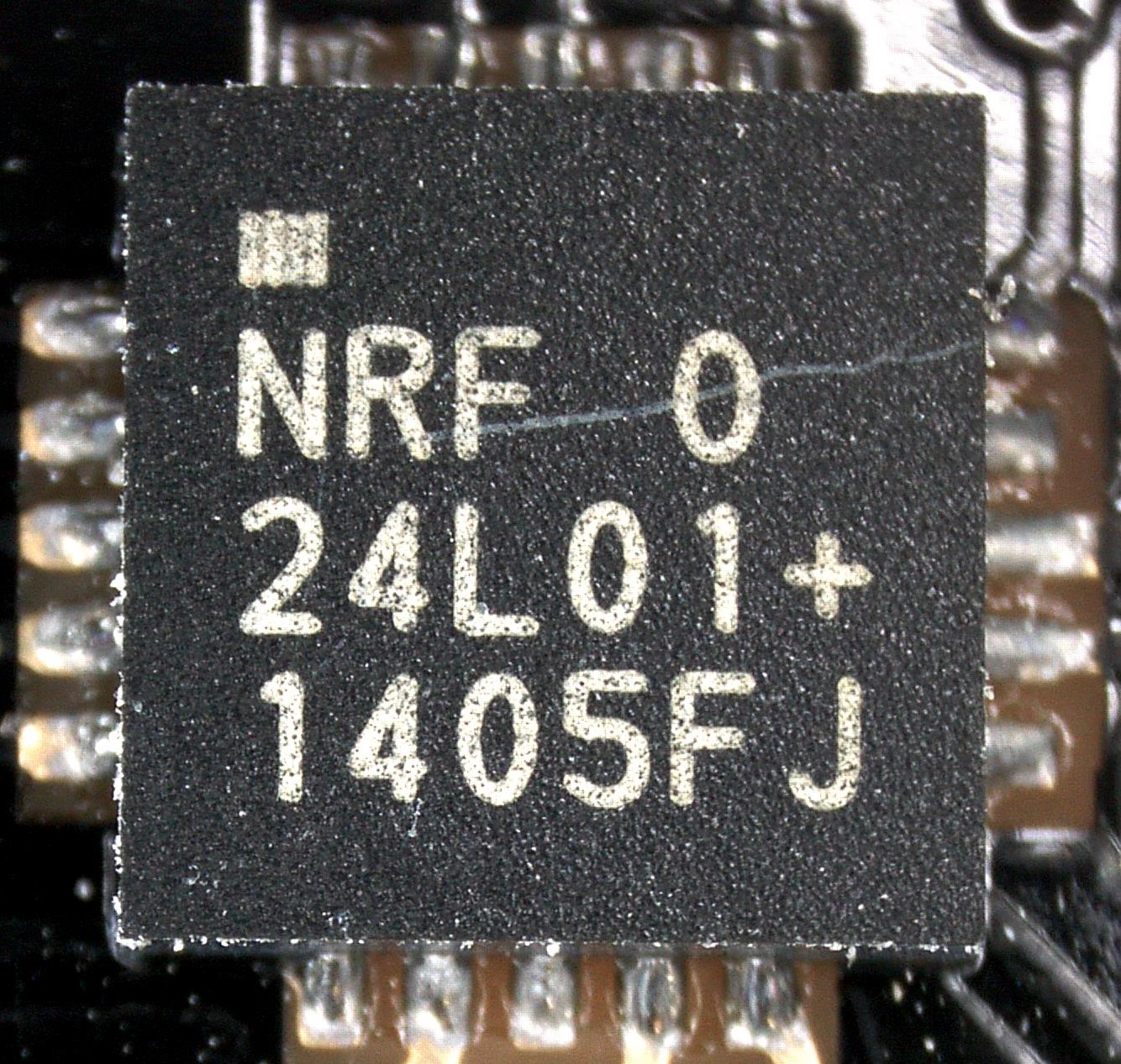
    I just now opened up the third Itead module to see if it was any different. Lo and behold, it is:

    3rd.jpg
    closeup.jpg

    This may be the strangest chip yet. Rather than a dot above the N, it looks like a rectangle. In addition, there's some plastic nub of some kind above the R. Lastly, the "1" font seems more similar to the allegedly fake chip than the chip Hek thinks is genuine.

    So, I just now ran the ping-pong test on it, and it performs even worse than the allegedly Itead modules I photographed earlier. When ping-ponging with one of those, the percentage of lost packets is 99.92% out of 90,000 packets.

    I don't know what to make of all this, but it doesn't look good.


  • Admin

    The nub almost looks like a 3d variant of the Nordics logo. Have they done this to make it harder to copy/clone?

    Are you using the same type of chip on both ends? I imagine intercompability could be an issue when mixing different fake once or with genuine chip.


  • Hero Member

    @hek said:

    Are you using the same type of chip on both ends?

    No. I purchased three modules from EpicTinker, and only one was like that. The other two were the same as the post I made earlier today.


  • Admin

    Ok, 99.92% packet loss is extremely bad. Are you sure you're giving it enough juice?


  • Hero Member

    @hek said:

    Ok, 99.92% packet loss is extremely bad. Are you sure you're giving it enough juice?

    Good question. What I've done so far is plug them into a couple of RFToys:
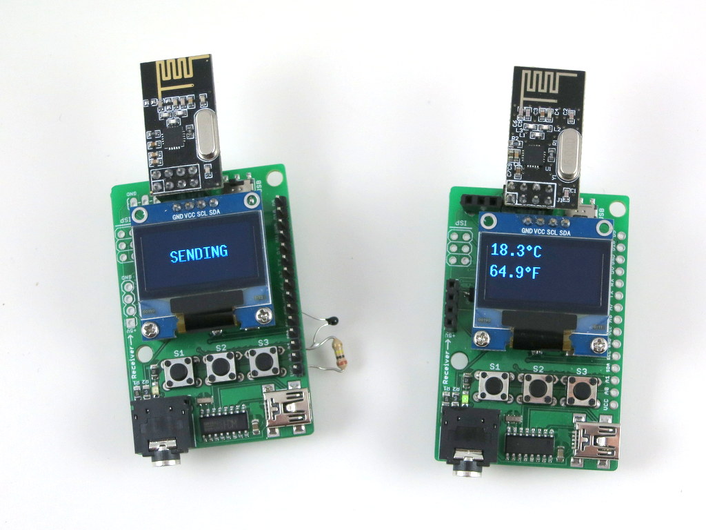
    RFToys.jpg

    so they're getting as much juice as the RFToys are giving them.

    I've been assuming that an RFToy would give them enough juice, but maybe that's a faulty assumption.


  • Hero Member

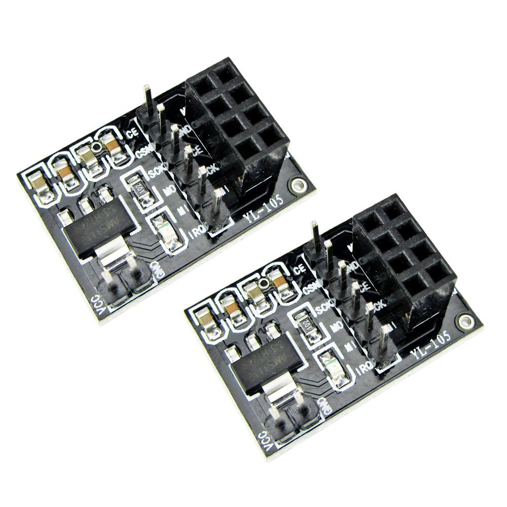
    OK, for easy testing, I just now ordered some socket adapters:
    adapter.jpg

    and should receive them on Tuesday. Also, instead of RFToys, I'll try driving them from Arduino Mega2560's. Does anyone here have experience to know whether the socket adapters will supply sufficient juice? I would hope so, as it would seem to be its primary function, but if anyone knows for sure one way or the other, please post.

    Meanwhile, I may try powering the modules using bench power supplies.


  • Hero Member

    If worse comes to worst, I'll just move ahead using blob modules. Who knows what they are, but could it be that they're actually better than genuine Nordic NRF24L01+'s?


  • Hero Member

    @NeverDie do you use a good power supply?


  • Hero Member

    @Moshe-Livne said:

    @NeverDie do you use a good power supply?

    Define "good". 😊

    I've been powering through nominal 5v USB, either through a computer's USB port for the master trasceiver (so, typically 500ma peak current) or through a typical USB charger module (typically nominal 5v 1amp or better peak current) for the slave echo transceiver. I'm not sure how the RFToy steps it down to 3.3v, or what the peak current available is on an RFToy at 3.3v. It seems good enough for the blob modules, so I (perhaps erroneously) assumed it should be good enough for the alleged NRF24L01+ modules. I'm aware some people have been getting better results using 10uF capacitors. In one of the threads it was claimed that only the fake NRF24L01_modules benefit from using capacitors(?), so I haven't rushed to embrace using capacitors. However, if you think it advisable, I could certainly try that.


  • Hero Member

    @NeverDie I do not use capacitors but I have noticed that the quality of the power supply is important but USB from a computer should have very little noise so that is not the reason.
    If you happen to have capacitors, would be interesting to see how they effect the results.
    @hek (or anyone else who knows what they are doing), as this seems to be a universal problem, why don't you start a github sketch with simple regression results that will evolve with time? we can also start a google drive spreadsheet to collect the results so we can record who we bought it from, include a photo and the results. Although the Chinese merchants can be fickle with they supply chain, at least on aliexpress you can verify beforehand with them that you are getting specific things and if you get something else you just don't pay. It is possible to establish good and reliable supply with them if they see that it brings them consistent returns and rating - I have done that with components for my LED lights. But we need a simple way of telling what we get....


  • Hero Member

    I looked just now at section 10.4 of the Nordic Semiconductor spec sheet for the NRF24L01+, and if I'm reading this right, it does make specific recommendations that may be worth repeating here:

    "The nRF24L01 DC supply voltage should be decoupled as close as possible to the VDD pins with high performance
    RF capacitors, see Table 26. on page 69. It is preferable to mount a large surface mount capacitor
    (for example, 4.7μF ceramic) in parallel with the smaller value capacitors. The nRF24L01 supply
    voltage should be filtered and routed separately from the supply voltages of any digital circuitry."

    I'm not sure if that's advocating the use of a large capacitor (such as a 4.7uF), or merely stating that if a large surface mount capacitor is used, then it's preferable it be mounted in parallel. I think it may be advocating. Can anyone here resolve the ambiguity? Would a 10uF capacitor commonly added by some people be relevant to this, or would it literally need to be a surface-mount component to qualify? Also, since it did specifically mention ceramic, is it important that it be ceramic rather than some other type? And if so, what type of ceramic capacitor would be best?

    Does supplying 3.3v from a voltage regulator right near the module, as in the adapter module I picture above, help provide a supply voltage that's separately filtered and routed, in part by putting it close to the NRF chip? I ask because it also says "Full swing digital data or control signals should not be routed close to the crystal or the power supply lines."


  • Hero Member

    @NeverDie No expert so just regurgitating what I read here on other threads:
    The capacitor serves two purposes:

    1. give the module extra juice while transmitting
    2. clean and smooth the noise on the power

    for (1), electrolite capacitor is good enough. for (2), people here said that ceramic is much better as it has all sorts of good qualities that has 3 or 4 letters acronyms. (not an expert!)

    the capacitor needs to be mounted as closely to the module otherwise the legs serves as antenna for interference or something.

    if you have a good power supply that produce good, clean 3.3v (a battery is a good example), connecting it directly to the nrf vcc is better than taking the 3v3 from the arduino.


  • Hero Member

    @Moshe-Livne said:

    @NeverDie No expert so just regurgitating what I read here on other threads:
    The capacitor serves two purposes:

    1. give the module extra juice while transmitting
    2. clean and smooth the noise on the power

    for (1), electrolite capacitor is good enough. for (2), people here said that ceramic is much better as it has all sorts of good qualities that has 3 or 4 letters acronyms. (not an expert!)

    the capacitor needs to be mounted as closely to the module otherwise the legs serves as antenna for interference or something.

    if you have a good power supply that produce good, clean 3.3v (a battery is a good example), connecting it directly to the nrf vcc is better than taking the 3v3 from the arduino.

    Thanks for the good info. . Since it's better for both MySensors and Itead to have a good working relationship where such matters can be quickly resolved, for now I'm going to hold off on soldering in the event Itead (the manufacturer) wants to inspect the modules I received in the same condition that I received them. Hopefully Hek will soon post an update from Itead regarding whether the modules are genuine or not. In addition to what has already been discussed, the packaging does not exactly match what Itead has shown on their website, judging from a post by Sparkman in a different thread related to this.

    I ordered from one of Itead's officially designated distributors, so I hope Itead stands behind their product and what was delivered. I really do hope I haven't been Shanghaied, but if that's how it shakes out, at least I limited the damage by purchasing only 3 modules to begin with rather than the larger number I'll ultimately be ordering.


  • @NeverDie

    This is Jerry from ITEAD.
    The Module we sell is original.
    Can you provide me your contact information?
    We will ask Nordic FAE in your country to contact you and test the module together with you.
    Just post the test result publicly on the forum.


  • Hero Member

    @jerry said:

    @NeverDie

    This is Jerry from ITEAD.
    The Module we sell is original.
    Can you provide me your contact information?
    We will ask Nordic FAE in your country to contact you and test the module together with you.
    Just post the test result publicly on the forum.

    Hi Jerry,

    Thanks for your fast response to my post.

    Geographically I'm in Austin, Texas (USA). I don't see a way to PM you with my email address, as it doesn't look as though this forum supports private messaging. However, if you like I can post a temporary alias email address here to facilitate our initial exchange of contact info. Or, if you prefer to post your email address, I can email you from my email address, and thereby connect that way. Would that work?

    Yes, I'd be happy to publish the test results on the forum. The more transparency, the better for everyone.


  • @NeverDie

    Good, then just provide me the temporary alias email address.


  • Admin

    @NeverDie said:

    I don't see a way to PM you with my email address, as it doesn't look as though this forum supports private messaging.

    Just click on a avatar and press the "Chat" button. The messages is stored just like old-style PM.


  • Hero Member

    @hek said:

    @NeverDie said:

    I don't see a way to PM you with my email address, as it doesn't look as though this forum supports private messaging.

    Just click on a avatar and press the "Chat" button. The messages is stored just like old-style PM.

    Thanks for explaining that. As a result, I just sent Jerry my contact info that way.


  • Mod

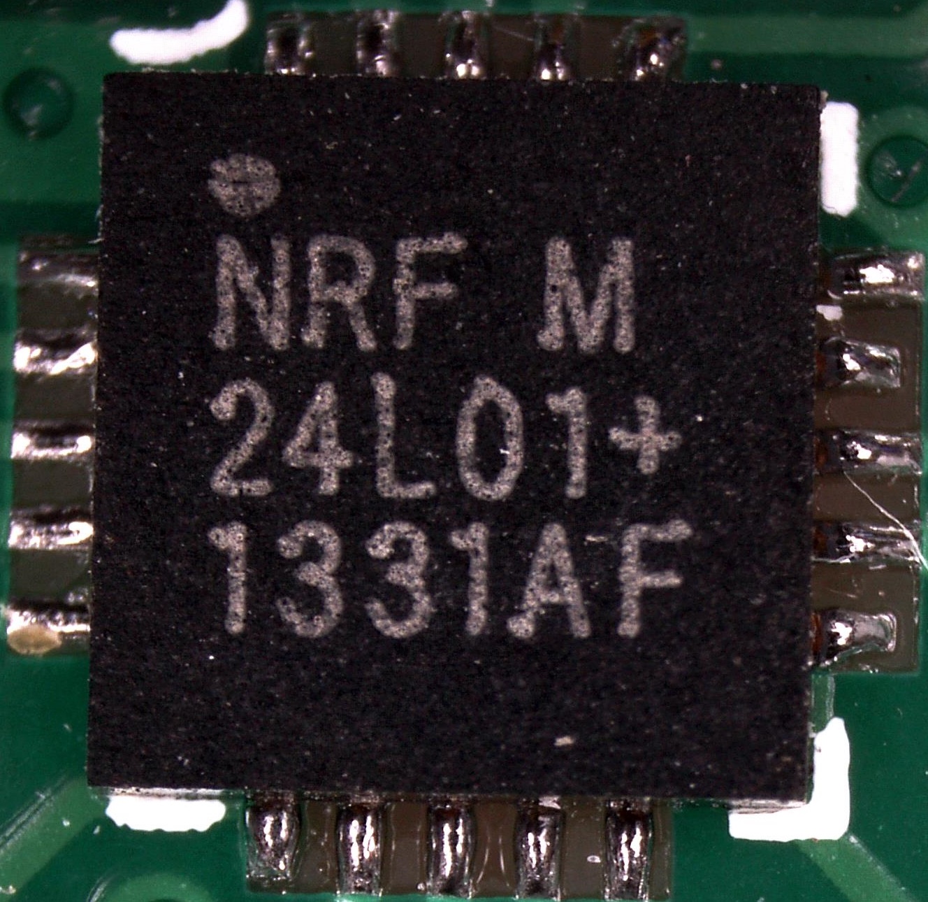
    An overview of the module I have lying around (origin is unclear, as I don't really keep track of where they come from)
    The chip close-ups were taken using a microscope, so they have far higher resolution then shown in the table (right-click & show image to view at native resolution) .

    Datecode YYWWLL Module top Module bottom Closeup Fake/Genuine
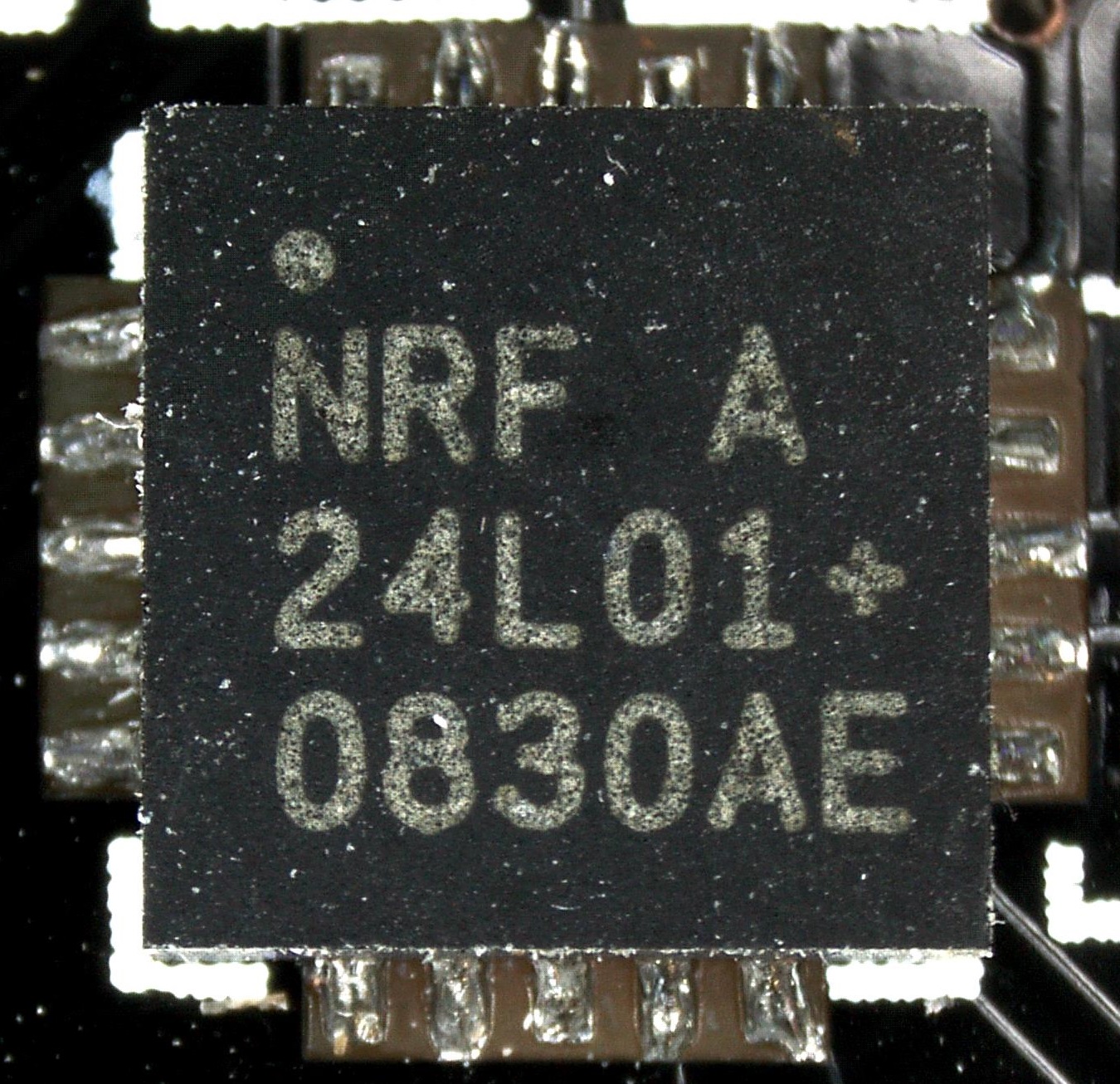
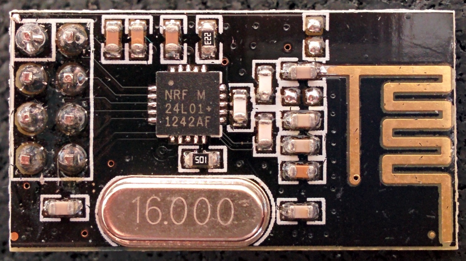
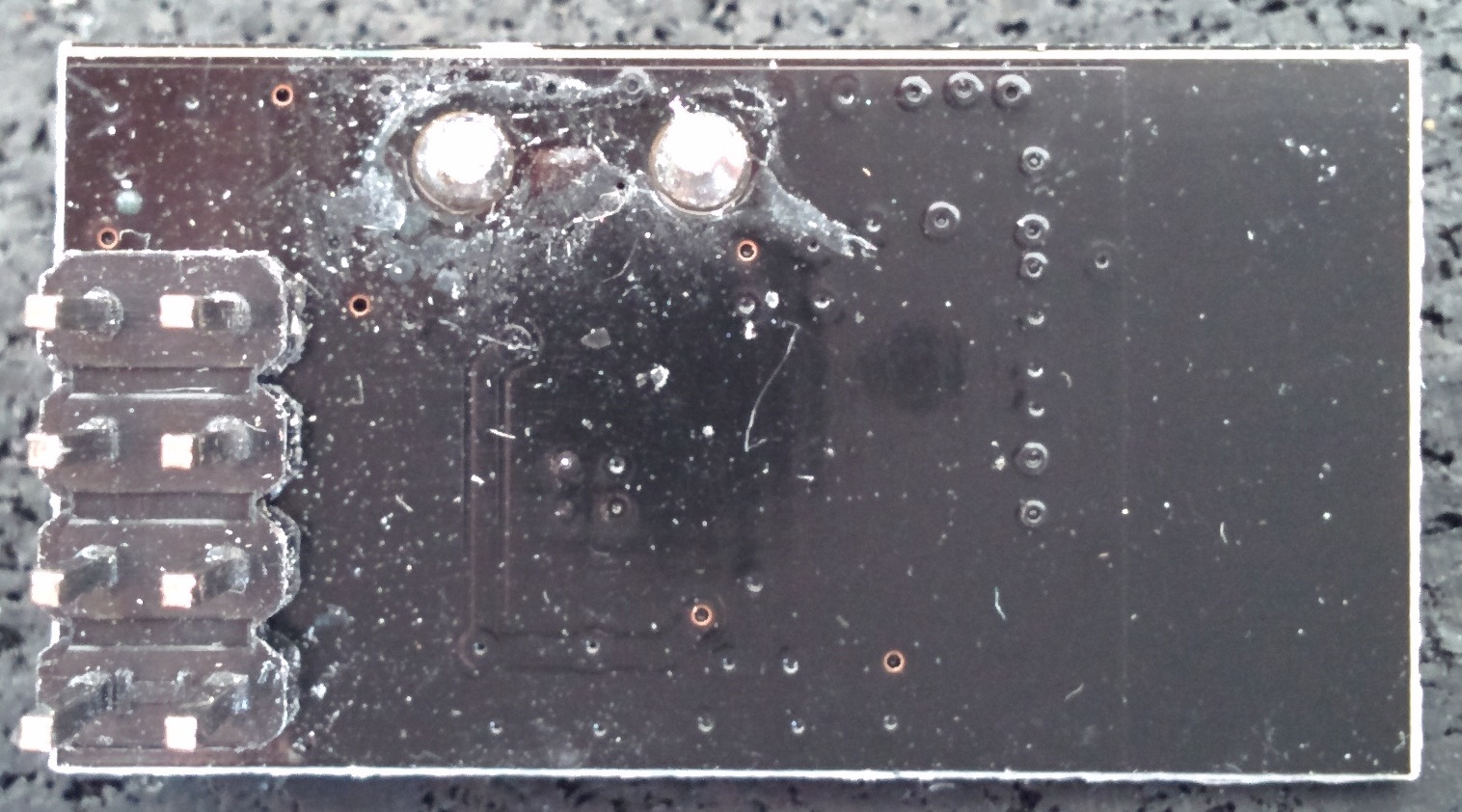
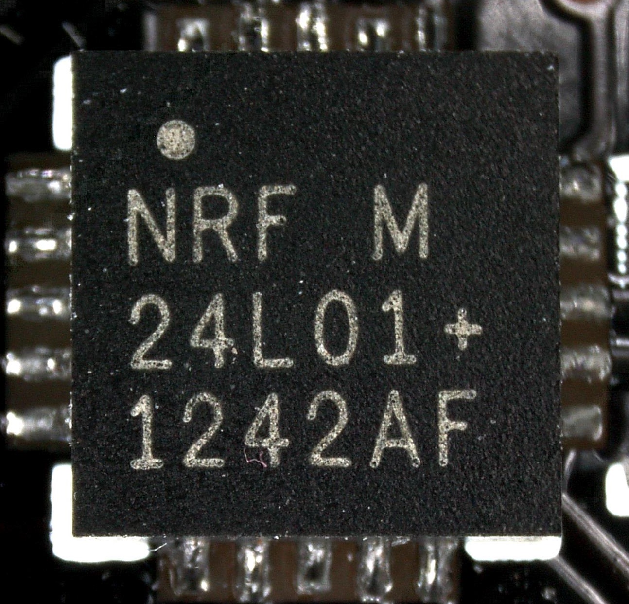
    0830AE 2015-07-27 18.59.21.jpg 2015-07-27 18.59.32.jpg 20150727_0005.jpg Genuine? Datecode 0830 indicates production wk30 2008. nRF24L01+ was launched in 2008
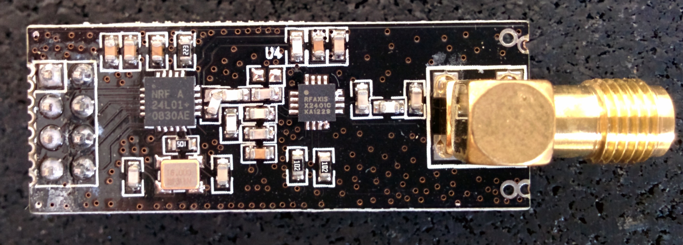
    1242AF 2015-07-27 18.53.12.jpg 2015-07-27 18.53.28.jpg 20150727_0006.jpg Known counterfeit, according to this
    1322DQ 2015-07-27 18.55.35.jpg 2015-07-27 18.55.45.jpg 20150727_0007.jpg
    1331AF 2015-07-27 18.56.26.jpg 2015-07-27 18.56.34.jpg 20150727_0008.jpg Known counterfeit, according to this
    1405FJ 2015-07-27 18.59.00.jpg 2015-07-27 18.59.08.jpg 20150727_0003.jpg
    1408AF 2015-07-27 18.54.33.jpg 2015-07-27 18.54.41.jpg 20150727_0002.jpg Probably fake (identical to left one bottom of the page

  • Admin

    Great pictures! What microscope are you using?

    I can't see anyone having the hole in the +-sign...


  • Mod

    @Moshe-Livne said:

    why don't you start a github sketch with simple regression results that will evolve with time?

    I'm thinking about a simple sketch, based of the nRF24 Sniffer's code, which connects two radios and checks on air how a radio communicates. This should allow detecting the inverted NO_ACK bit (see Jay Tyzzer's comment here) to immediately quilify a module as fake when detected.
    Of course this doesn't mean it's genuine when doesn't have the bit inverted, but the sketch could also dump register settings to be able to detect a pattern.


  • Mod

    @hek said:

    What microscope are you using?

    This one. It's sold under various names/brands (e.g. Oitez e-scope).
    I really needed it to hand-solder those QFN's 😉


  • Mod

    @hek said:

    I can't see anyone having the hole in the +-sign...

    Yup, so they're all genuine... PROBABLY NOT!
    Ehhrrmmm fake probably...


  • Hero Member

    @Yveaux wonderful! Even if fake, ones with correct ack bit will probably work better so its a step in the right direction


  • Hero Member

    @Yveaux said:

    An overview of the module I have lying around (origin is unclear, as I don't really keep track of where they come from)
    The chip close-ups were taken using a microscope, so they have far higher resolution then shown in the table (right-click & show image to view at native resolution) .

    Datecode YYWWLL Module top Module bottom Closeup Fake/Genuine
    0830AE 2015-07-27 18.59.21.jpg 2015-07-27 18.59.32.jpg 20150727_0005.jpg Genuine? Datecode 0830 indicates production wk30 2008. nRF24L01+ was launched in 2008
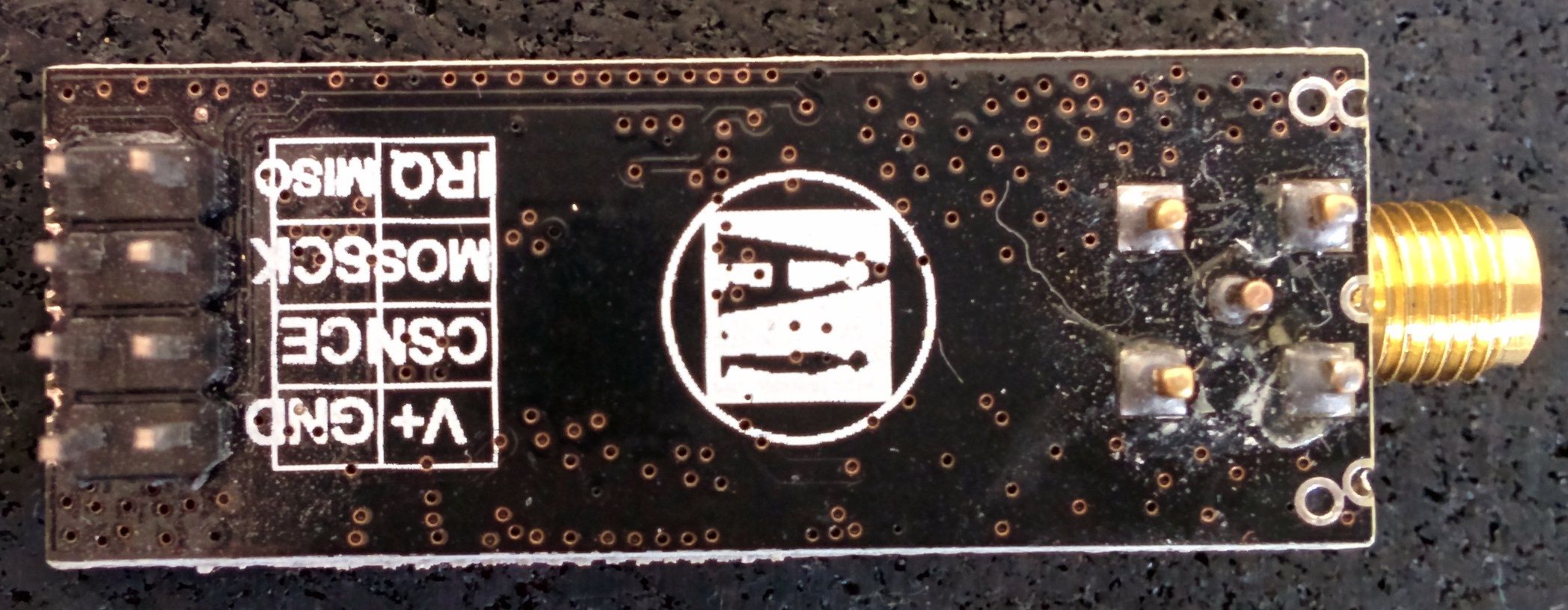
    FWIW, the 0830AE date code is only a little earlier (4 weeks?) than the 0834AF datecode on the chip above in Hek's post where Hek alleges the module is genuine.


  • Hero Member

    @Yveaux said:

    I really needed it to hand-solder those QFN's 😉

    How hard would it be to desolder a bogus NRF chip and then solder a known good NRF24L01+ (purchased either directly from Nordic, if Nordic does that, or else from a trusted distributor like Digikey) in its place? Perhaps in this way the modules can be given a second life of sorts.


  • Hero Member

    @Yveaux: Those are wonderful photos! Thanks so much for posting them. 😄 Did you use the microscope for the module shots also, or just the NRF chip closeups?

    Since you have a nice module collection that spans different NRF chips and also different module types, have you noticed whether any of your modules stand out head-and-shoulders above the others as having clearly better performance?


  • Lol, I just checked all of my radios from Alice1101983 and they are all dated 1242AF - FAKES! I have 20 from two orders of 10 radios each placed about six months apart (10/14 & 4/15) and they all have the same production date. They do work but I have occasional and random node hangup. This is an ongoing problem which I have been unable to troubleshoot. @hek, we might want to change the vendor in the MySensors store.


  • Hero Member

    Here's a module that is itself surface mountable. It seems like roughly half the footprint of typical modules.
    smm.jpg
    Anyone have suggestions on how best to cheaply hook it up to an arduino? Not sure, but the pin pitch might be 1.27mm. I do have arduino prototyping shields, and there do seem to be 7 pin areas meant for soldering on something with surface mount (see SOIC area in upper left below):
    protoshield.jpg
    Unfortunately, there are only 7 pads on the SOIC that I can solder it to, and the ground pin is on the end, with the IRQ next to it.
    pinout.jpg
    Not ideal! Should I try soldering a wire to the ground pin but solder the rest of the pins to the SOIC pads on the prototyping board? Seems like that may be the cleanest way to do it.

    That might be fine if using an Uno, but what about if using a pro mini? How best to connect it then? Anyone here already doing it?

    As a ghetto method I could also run jumper pins through each through-hole and solder into place, and then run each wire to the proper pin on the pro mini and solder into place, but... not very elegant. Are there better ways I'm not aware of?


  • Hero Member

    Anyone know by what method Nordic prints the lettering on the chips? In looking at Yveaux's CSI-like photos, from chip-to-chip all of the letters have some amount of black mixed in, but on some they seem to be gaps left by air bubbles (so you're seeing through paint gaps to the black background) from the lettering being sprayed on, and on others the black seems like black dust or or something that was sprinkled on top after the lettering was applied. So, if you look closely through a microscope, some differences do seem to emerge. Under magnification, the lettering on the 1331AF is visibly sloppy, almost as if printed by a professional cake decorator from your local bakery.

    Anyone know what some of the other lettering is supposed to mean? e.g. M, AF, EV, CH, A, 0, CL, AE, DQ, FJ, or FY? On Hek's genuine chip, it seems blank after the NRF, whereas that's not true for any of the other chips.


  • Hero Member

    My "regular" modules were bought from gc_supermarket and the NRF chips all have the following printing. There is no circle in the center of the +.

    .
    NRF  T
    24L01+
    1420JB
    

    My LNA/PA modules were bought from alice11011983 and the NRF chips have the following printing. There is a circle in the center of the + on the first set, but not the second set.

    .
    NRF  M
    24L01+
    1431FC
    
    .
    NRF  O
    24L01+
    1417GP
    

    I'll try to grab some pics this weekend.

    Cheers
    Al


  • Hero Member

    Update: I provided Itead with my contact information, and they will try to arrange for a Nordic FAE to contact me.

    As there's no telling how long the above might take to resolve, I decided to roll the dice again and ordered three of these modules:

    red1.JPG
    red2.JPG
    I hope to receive them by later in the week. I'm hopeful, but only slightly optimistic. If there's interest, I'll post closeups after I receive and test them.

    I also ordered more blob modules, but from a different source than the two I already have, so who knows what I'll actually receive. If it turns out blob modules from different sources are all about the same, I might standardize on that and simply move on. The two that I have work well enough that I wouldn't mind doing that, though it may put me on a fork from the rest of you. My only reluctance is that we'd all be more productive if we can find some way to leverage a common platform, so that remains my preference (and hope) for the long-term.


  • Mod

    @NeverDie said:

    Did you use the microscope for the module shots also, or just the NRF chip

    Only the chips were shot using my microscope. The field of view is simply too small to shoot the whole module.

    Only > Since you have a nice module collection that spans different NRF chips and also different module types, have you noticed whether any of your modules stand out head-and-shoulders above the others as having clearly better performance?

    No, but I had troubles mixing different modules in the past (even the NO_ACKs were involved iirr), so I'm very interested to know which ones are genuine.


  • Mod

    @NeverDie said:

    Anyone know by what method Nordic prints the lettering on the chips?

    Yes, it's in the data sheet. The date code is in YYWWLL which stands for year & week of production, an LL indicates wafer lot. The top right code indicates the production location (first letter) followed by optional letter indicating engineering sample.

    Nordic is fabless so only they know what the location letters mean.

    The text is normally written using a laser scriber, so no ink is involved.
    Thinking of it, differences in font/thickness etc. can be caused by different laser scribers at different production facilities (or even within one facility) so I'm starting to doubt if it will help us in distinguishing fakes from genuine.


  • Hero Member

    @Yveaux said:

    @NeverDie said:

    Anyone know by what method Nordic prints the lettering on the chips?

    Yes, it's in the data sheet. The date code is in YYWWLL which stands for year & week of production, an LL indicates wafer lot. The top right code indicates the production location (first letter) followed by optional letter indicating engineering sample.

    Nordic is fabless so only they know what the location letters mean.

    The text is normally written using a laser scriber, so no ink is involved.
    Thinking of it, differences in font/thickness etc. can be caused by different laser scribers at different production facilities (or even within one facility) so I'm starting to doubt if it will help us in distinguishing fakes from genuine.

    Thanks for pointing that out. Looking at the version 1.0 spec sheet (available at http://www.nordicsemi.com/eng/Products/2.4GHz-RF/nRF24L01P), I see it covered in section 13.1 and 13.2.

    Curiously, according to the spec sheet, the chips should be marked "nRF", not "NRF".


  • Mod

    @NeverDie said:

    Curiously, according to the spec sheet, the chips should be marked "nRF", not "NRF".

    Maybe they hoped the copycats would also copy this error, but unfortunately they didn't 👊


  • Hero Member

    @Sparkman said:

    My "regular" modules were bought from gc_supermarket and the NRF chips all have the following printing. There is no circle in the center of the +.

    .
    NRF  T
    24L01+
    1420JB
    

    My LNA/PA modules were bought from alice11011983 and the NRF chips have the following printing. There is a circle in the center of the + on the first set, but not the second set.

    .
    NRF  M
    24L01+
    1431FC
    
    .
    NRF  O
    24L01+
    1417GP
    

    I'll try to grab some pics this weekend.

    Cheers
    Al

    Hi Al,
    Funny that you happen to mention gc_supermarket, because just yesterday I was noticing that they had good pricing on blob modules. These visually resemble the two blob modules I have and which seem to perform quite well at 1mbps air datarate. Intriguingly, the listing title says "Power enhanced version Compatible NRF24L01" and in the description it says:
    "This module is design to solve the problem of small power in NRF24L01 module, its distance is far away than NRF24L01
    Please download the data in below link
    http://www.ai-thinker.com/forum.php?mod=viewthread&tid=411&extra=page%3D1 "

    It would be easy to dismiss this as gibberish or as a failed attempt at chinglish, except for the fact that my two blob modules do, in fact, seem to have much better range than any of the "regular" NRF24L01+ modules I've tried so far. So, whether deserved or not, that does seem to give gc_supermarket more credability in my eyes than a lot of other re-sellers. Also, whether by luck or intent, they referred to it as "NRF24L01", not "NRF24L01+", which is also closer to reality, as it doesn't support 250kbps. So, in my book they get some credibility points for that also.

    Have your transactions to date with gc_supermarket gone well?


  • Hero Member

    @NeverDie said:

    Have your transactions to date with gc_supermarket gone well?

    Overall yes. First shipment from them got lost, but they replaced the shipment right away without any argument and it showed up ok. The modules seem to be a good quality with nice soldering and the flux cleaned up properly. I haven't done any packet loss testing with them, but have had good range with them (@250kbps).

    Cheers
    Al


  • Hero Member

    Here's a link which lists chips similar to the NRF24L01+ (there are many more than I had supposed), and it also highlights some of their differences: http://sigrok.org/wiki/Protocol_decoder:Nrf24l01
    Especially useful is the mirror of the datasheets.

    I have a hunch that a simple way to differentiate among the various chips might be to measure the amount of current consumed in various modes (e.g. standby, powerdown, etc), because those numbers are also given in the datasheets. Anyone tried that?


  • Hero Member

    I just placed an order on Ali Express for four NRF24L01+ modules that look similar to the one Hek says is genuine: http://www.aliexpress.com/item/Free-shipping-Original-Genuine-NRF24L01-Wireless-Module-2-4G-wireless-communication-module-2-54mm-Interface-2/1781618813.html I mainly picked this seller because he will be sending by ePacket for only 4 cents extra, and that should mean much faster delivery (5 to 15 days). Also, the seller has decent feedback and is promising that the chips are "original" and "genuine." So, with shipping, the modules will be costing me an average of $2.82 each. I hope they're worth not just the money, but also the wait.

    I would have preferred to first receive and then test the modules I've already ordered to see if they are genuine, but given the shipping time from Asia, I'm doing parallel orders in the hope of getting at least one shipment of genuine NRF24l01+ modules up and working fairly soon. Doing the orders serially would have run the risk of the procurement process taking too long.


  • @NeverDie : Can you please post the sketch you use to test your NRFs modules. I just recieve 10 today from Itead. Same packaging that the ones you recieve. I just want to compare result in same conditions.


  • I ordered some surface-mounted by accident.
    2015-07-29 10.04.56.jpg

    The reading say:
    NRF M
    24L01+
    1436AH

    They seem to work fine, but if somebody has an packet-loss testing sketch i would test it.


  • Hero Member

    @Fabien said:

    @NeverDie : Can you please post the sketch you use to test your NRFs modules. I just recieve 10 today from Itead. Same packaging that the ones you recieve. I just want to compare result in same conditions.

    OK, sure. It started out as RF toy code, and then I just evolved it. It contains a lot of commented out code that I haven't bothered to delete. If that gets in the way of your understanding, just delete the code that's commented out. Aside from that, it's straightforward.

    Here's the main transmitter code. After compiling and uploading, you should open a serial window on your computer to read the statistics it prints out:

    /*
     nRF24Sender Demo for RFToy
     
     This demo shows how to use RFToy to make a
     wireless temperature sensor. This is the
     sender module which transmits the current
     temperature value to a receiver module. The
     demo uses the Mirf library.
     
     This demo uses a 100K resistor and 100K
     thermistor to form a simple temperature 
     sensor. Pin A1 is used to read the value. 
     The connection is:
     VCC->100K->A1->thermistor->GND
      
     Written by Jonathan Goldin @ Rayshobby LLC
     Nov 2014
     For details, visit http://rayshobby.net/rftoy
    */
    
    #include <SPI.h>
    #include <Mirf.h>
    #include <nRF24L01.h>
    #include <MirfHardwareSpiDriver.h>
    #include <U8glib.h>
    
    U8GLIB_SSD1306_128X64 u8g(U8G_I2C_OPT_NONE);	// I2C / TWI 
    
    void setup(){
      Serial.begin(115200);
      Serial.println("Starting...");
       
      /*
       Set ce and csn pins
       */
      
      Mirf.cePin = 17;
      Mirf.csnPin = 16;
      
      Mirf.spi = &MirfHardwareSpi;
      Mirf.init();
      
      /*
       * Configure reciving address.
       */
       
      Mirf.setRADDR((byte *)"clie1");
      
      /*
       * Set the payload length to sizeof(unsigned long) the
       * return type of millis().
       *
       * NB: payload on client and server must be the same.
       */
       
      //Mirf.payload = sizeof(long);
      Mirf.payload = sizeof(long);  
      /*
       * Write channel and payload config then power up reciver.
       */
       
      /*
       * To change channel:
       * 
       * Mirf.channel = 10;
       *
       * NB: Make sure channel is legal in your area.
       */
       
        // we use channel 90 as it is outside of WLAN bands 
      // or channels used by wireless surveillance cameras 
      //Mirf.channel = 90;
      
      Mirf.config();
      
        
      //This register value is not remembered between power cycles.
      //It defaults to 0x0F.
      //It should be initialized each time if different than 0x0F.
      Mirf.configRegister(RF_SETUP,0x07); //0x0F is 2mbps, max Tx power 
                                          //0x07 is 1mbps, max Tx power
                                          //0x2F is 250kbps, max Tx power.
      Serial.println("OTA datarate set to  1Mbps.  Transmit Power set to Maximum.");
      
      // Read and print RF_SETUP
     byte rf_setup = 0;
     Mirf.readRegister( RF_SETUP, &rf_setup, sizeof(rf_setup) );
     Serial.print( "rf_setup = " );
     Serial.println( rf_setup, BIN );
      // OLED
      u8g.firstPage();
      do{
        uint8_t h;
        u8g.setFont(u8g_font_10x20);
        u8g.setFontRefHeightText();
        u8g.setFontPosTop();
        h = u8g.getFontAscent()-u8g.getFontDescent();
        u8g.drawStr(29,(u8g.getHeight()-h)/2,"Tx Sender");
      } 
      while(u8g.nextPage());
      Mirf.setTADDR((byte *)"serv1");
      
      Serial.write("Sending...\r\n"); 
      delay(200);
    } // End of *Setup*
    
    
    long temp;
      int temp1;
      int temp2;
      long timeTxSent;
      long timeRxReceived;
      long roundTrip;
      byte age1=52;
      byte age2=11;
      long txCounter=0;
      long matchCount=0;
      long differentCount=0;
      long lostCount=0;
      long cumulativeRoundTrip=0;
      long averageRoundTrip=0;
      boolean packetLost=false;
      float packetErrorRate=0;  //no errors yet, and maybe there never will be.
      float lostPacketRate=0;  //no packets lost yet.
      const int statusFrequency=500;  //How many iterations of main loop before printing status info.
      long minRoundTrip=9999; //value will be driven down when program runs
      long maxRoundTrip=0;  //value will be driven up when program runs
      
    void loop(){


      txCounter++;
      packetLost = false;  //It can't be lost, because it hasn't even been sent yet.
      
      temp = txCounter;  //getTemp(resistance);
      temp1=temp;
      
      timeTxSent=micros();
      Mirf.send((byte *)&temp);  


      while(Mirf.isSending()){
      }
    
      /*
      Serial.write("temp=");
      Serial.print(temp,DEC);
      Serial.write("\r\n");
      Serial.write("temp1=");
      Serial.print(temp1,DEC);
      Serial.write("\r\n");
      Serial.write("Finished sending.\r\n");
      */
      //delay(10);
      unsigned long time = millis();
      while ((!packetLost) && (!Mirf.dataReady())){
        //Serial.println("Waiting");
        if ( ( millis() - time ) > 8 ) {
          //Serial.println("Timeout on response from Rx Echo Reflector!");
          lostCount++;
          packetLost=true;
        }
      }
      
      if (!packetLost) {
      Mirf.getData((byte *) &temp);  
      timeRxReceived=micros();
      temp2 = temp;  
      roundTrip =  timeRxReceived - timeTxSent;
      if (roundTrip < minRoundTrip) {
        minRoundTrip=roundTrip;
      }
      if (roundTrip > maxRoundTrip) {
        maxRoundTrip = roundTrip;
      }
      if(temp1 == temp2){  
        matchCount++;
        cumulativeRoundTrip += roundTrip;
        averageRoundTrip = cumulativeRoundTrip/(txCounter-lostCount-differentCount);
      } else {
        differentCount++;
        Serial.println("***DIFFERENT**");
          Serial.write("temp1=");
          Serial.println(temp1, BIN);
          Serial.write("temp2=");
          Serial.println(temp2, BIN);
      }
      
      if ((txCounter%statusFrequency)==0) {
        /*
        if(temp1 == temp2){  
          Serial.print("Match");
        } 
        else {
          Serial.println("***DIFFERENT**");
        }
        Serial.write(",");
        */
      }
      }
      
      lostPacketRate = 100*((float)(lostCount))/((float)txCounter);
      
      if ((txCounter%statusFrequency)==0) {
       
        Serial.print(txCounter);
        Serial.write(",lost=");
        Serial.print(lostPacketRate);
        /*
        Serial.write("%,T=");
        Serial.print(temp,DEC);
        //Serial.write(".  ");
        Serial.write(",T1=");
        Serial.print(temp1,DEC);
        //Serial.write(".  ");
        Serial.write(",T2=");
        Serial.print(temp2,DEC);
        */
        Serial.write("%,RT=");
        Serial.print(roundTrip,DEC);
        Serial.write(",minRT=");
        Serial.print(minRoundTrip);
        Serial.write(",maxRT=");
        Serial.print(maxRoundTrip);
        Serial.write(",aRT=");
        Serial.print(averageRoundTrip,DEC);
        Serial.print(",#lost=");
        Serial.print(lostCount);
        //Serial.write(",mat=");
        //Serial.print(matchCount);
        Serial.write(",diff=");
        Serial.print(differentCount);
        Serial.write("\r\n");
        delay(100); //give time for it to print out
        //txCounter = 0;  //restart gathering statistics
      }
    
      
      /*
      delay(1000);  // keep the 'sending' message displayed on OLED for 1 sec
      u8g.firstPage();
      do{
      } while(u8g.nextPage());
    
      delay(2000);  // wait for 2 seconds till next transmission
      */
    }  //End of main loop. 
    

    Here's the code for the receiver node. It doesn't need to be plugged into a computer:

    /*
     nRF24Receiver Demo for RFToy
     
     This demo shows how to use RFToy to make a
     wireless temperature sensor. This is the
     receiver module which displays the received
     temperature value to OLED. The demo uses
     the Mirf library.
     
     Written by Jonathan Goldin @ Rayshobby LLC
     Nov 2014
     For details, visit http://rayshobby.net/rftoy
    */
    
    #include <SPI.h>
    #include <Mirf.h>
    #include <nRF24L01.h>
    #include <MirfHardwareSpiDriver.h>
    #include "U8glib.h"
    
    
    U8GLIB_SSD1306_128X64 u8g(U8G_I2C_OPT_NONE);	// I2C / TWI 
    
    void setup(){
      Serial.begin(115200);
      Serial.println("Echo Receiver.  Listening");
    
      Mirf.cePin = 17;  //???
      Mirf.csnPin = 16;  //???
      /*
       * Set the SPI Driver.
       */
    
      Mirf.spi = &MirfHardwareSpi;
    
      /*
       * Setup pins / SPI.
       */
    
      Mirf.init();
    
      /*
       * Configure reciving address.
       */
    
      Mirf.setRADDR((byte *)"serv1");
    
      /*
       * Set the payload length to sizeof(unsigned long) the
       * return type of millis().
       *
       * NB: payload on client and server must be the same.
       */
    
      Mirf.payload = sizeof(long);
    
      /*
       * Write channel and payload config then power up reciver.
       */
    
    
     // we use channel 90 as it is outside of WLAN bands 
      // or channels used by wireless surveillance cameras 
      //Mirf.channel = 90;
      
      Mirf.config();
        //This register value is not remembered between power cycles.
      //It defaults to 0x0F.
      //It should be initialized each time if different than 0x0F.
      Mirf.configRegister(RF_SETUP,0x07); //0x0F is 2mbps, max Tx power 
                                          //0x07 is 1mbps, max Tx power
                                          //0x2F is 250kbps, max Tx power.
      Serial.println("OTA datarate set to 1Mbps.  Transmit Power set to Maximum.");
      
      // Read and print RF_SETUP
     byte rf_setup = 0;
     Mirf.readRegister( RF_SETUP, &rf_setup, sizeof(rf_setup) );
     Serial.print( "rf_setup = " );
     Serial.println( rf_setup, BIN );
    
      
      u8g.firstPage();
      do{
        uint8_t h;
        u8g.setFont(u8g_font_10x20);
        u8g.setFontRefHeightText();
        u8g.setFontPosTop();
        h = u8g.getFontAscent()-u8g.getFontDescent();
        u8g.drawStr(19,(u8g.getHeight()-h)/2,"Echo Rx");
      } 
      while(u8g.nextPage());
      
    }  //End of *Setup* procedure
    
    void loop(){
      /*
       * A buffer to store the data.
       */
    
      byte data[Mirf.payload];
    
      /*
       * If a packet has been recived.
       *
       * isSending also restores listening mode when it 
       * transitions from true to false.
       */
    
      if(!Mirf.isSending() && Mirf.dataReady()){
        //Serial.print("Got packet: ");
    
        /*
         * Get load the packet into the buffer.
         */
    
        Mirf.getData(data);
    
        
        // Set the send address.
        Mirf.setTADDR((byte *)"clie1");
    
        /*
         * Send the data back to the client.
         */
    
        Mirf.send(data);
    
        /*
         * Wait untill sending has finished
         *
         * NB: isSending returns the chip to receving after returning true.
         */


        //Serial.println("Reply sent.");
      }
    }
    

    As background, here's a link to the RFToy:
    http://rayshobby.net/rftoy/
    Links to the RFToy library, as well as the hardware design, can be found there. It's all open source.

    This shows the pin assignments: https://github.com/rayshobby/rftoy-hw/blob/master/RFToy.png

    You'll need a pinout diagram to match-up those internal pins to the physical pins of whatever Arduino you're using. For instance, for an Uno, here's a pinout diagram which maps internal pins to physical pins:
    http://marcusjenkins.com/wp-content/uploads/2014/06/ARDUINO_V2.png
    That way you'll know how to properly wire-up your NRF24L01+ so that it works properly with the library code.

    So, I did that just now and tested it on the UNO, and so for the UNO the simplified wiring directions are:
    NRF24L01+Pin --- --> Uno Female Header Pin
    GND (1) ----------------------------> GND
    VCC (2) -----------------------------> 3.3V
    CE (3) ------------------------------> A3
    CSN (4) -------------------------------> A2
    SCK (5) --------------------------------> D13
    MOSI (6) --------------------------------> D11
    MISO (7) --------------------------------> D12
    IRQ(8) ---------------------------------> n/a

    The RFToy has an OLED screen that gets written to. You can remove that code if you wish, but leaving it in does no harm, even if you don't have an OLED screen on your arduino. I modified the code so that it's only written to during the setup loop, so regardless it shouldn't interfere with any of the measurements taken in the main loop..

    Hope that helps!


  • I just finish some tests with your sketch. With ITead Modules, I have 0.05% packet loss at 1mbps and about 15 meters with 1 wall.
    aRT is 1700. With NRF from electrodragon, I have same results aRT is a bit higher eg 2000.
    But during my tests, I found some issues :

    • With UNO I have more lost packets without extra capacitor. I think 3.3V output is not enough good. With Arduino Nano, it's ok
    • Quite different results when touching my dupont wires ...
    • When I let temp1 and temp2 output, there's a bug with synchro. It says it's always different but it's only dure to a shift with comparaison. If i just comment serial.output of temp1 an temp2 diff is always equal to 0

    I will make a test with RF24 from TMRh20 (used in MySensors).
    About Mysensors, I have a question : is there a configuration to retry packet sending and delay bewteen resend like radio.setRetries(2,15); ?

    So for me the Itead modules are good and electrodragon too.


  • Admin

    @Fabien said:

    is there a configuration to retry packet sending and delay bewteen resend like radio.setRetries(2,15); ?

    No, there isn't currently. You can always run a gw.setRetries() after gw.setup() has been called,


  • @hek : I just look in the library and see there is a retry RF24::setRetries(5,15); in MySensor::setupRadio and it is called by MySensor::begin


  • Admin

    Yes, thought you meant if there were any config options to set this...


  • Hero Member

    @Fabien said:

    I just finish some tests with your sketch. With ITead Modules, I have 0.05% packet loss at 1mbps and about 15 meters with 1 wall.
    aRT is 1700. With NRF from electrodragon, I have same results aRT is a bit higher eg 2000.
    But during my tests, I found some issues :

    • With UNO I have more lost packets without extra capacitor. I think 3.3V output is not enough good. With Arduino Nano, it's ok
    • Quite different results when touching my dupont wires ...
    • When I let temp1 and temp2 output, there's a bug with synchro. It says it's always different but it's only dure to a shift with comparaison. If i just comment serial.output of temp1 an temp2 diff is always equal to 0

    I will make a test with RF24 from TMRh20 (used in MySensors).
    About Mysensors, I have a question : is there a configuration to retry packet sending and delay bewteen resend like radio.setRetries(2,15); ?

    So for me the Itead modules are good and electrodragon too.

    Interesting! Thanks for reporting the results. I'm sure Itead will be happy to hear about it. 😄 BTW, what lettering is printed on the NRF24L01+ chips? Also, from where did you procure the modules (Itead headquarters?) and how long ago?

    Prior to this morning, I had been using only an RFToy (which is effectively an 8Mhz 3.3V Arduino Mini Pro), and differences between the number transmitted (temp1) and the number echoed back (temp2) were fairly rare. Because probably no one but me has an RFToy, I setup and tested using an Uno this morning to verify that I was giving the correct wiring instructions (above). I did notice a much greater rate of differences reported by the Uno than the RFToy, but I didn't pay attention to the details. From what you're saying, it sounds like it hasn't finished shifting all the bits from the Rx buffer before comparing temp1 to temp2? Am I understanding you right? If so, you could try adding, say, a 2ms delay before doing the comparison to allow the received data to fully settle before the comparison. It wouldn't affect the roundtrip timing, because it would be happening after the elapsed microseconds had been recorded. Without looking into it, I had thought that my use on the Uno of fairly long dupont jumper cables was injecting noise. On the RFToy, the connections are shorter, and no jumper wires are used.

    What size capacitor (how many Farads) have you found works best? What type (e.g. electrolytic, ceramic, film, etc.)?

    If you move the code over to TMRh20, would you mind posting it back to this thread? I think more people will be familiar with it than with the Mirf library. I only used Mirf because the RFToy code used it, and for simplicity that was my starting point.

    Is this the electrodragon NRF24L01+ module that you tested? http://www.electrodragon.com/product/nrf24l01/


  • Admin

    @Fabien
    Gotta love their product description...

    "The main advantage of it is cheap."


  • @hek : Yes but I havn't notable difference with the one from itead ! And you know it is clone.
    @NeverDie : The first 2 chip from Itead : 1443IA , not a dot but a square and too small to see if there is a hole inside the +. I think i don't investigate more with others sketch because with my dupont cable error rate can increase a lot when just touching a cable.
    I just setup a Iboard with PA+LNA from electrodragon and all my sensebender with clone from electrodragon too, and everything is working fine, up 20 meters without any problems.
    For security I will change my NRF with the ones from Itead and will keep my PA+LNA for milight gateway emulation.


  • Hero Member

    @Fabien said:

    @hek : Yes but I havn't notable difference with the one from itead ! And you know it is clone.

    Move your test nodes further apart, and keep increasing the distance until you start losing a higher percentage of packets. Most likely, as the separation distance and/or RF impairments increase, at some point one module or the other is going to perform much better than the other--that is unless they're using the same type of NRF chip. At least to date that's been my experience with the very few datapoints I've collected so far.


  • Hero Member

    @NeverDie If/when you get contact with nordic rep, it would be great if they can provide a sketch that does the testing. they probably have one...


  • Hero Member

    @Moshe-Livne said:

    @NeverDie If/when you get contact with nordic rep, it would be great if they can provide a sketch that does the testing. they probably have one...

    What kind of testing?


  • Hero Member

    @NeverDie

    1. Authentic module testing (they might be reluctant to give something like this as it can probably be used to make the copies closer to the original - but worth the try)
    2. QA testing - packet drop, etc at different speeds

  • Hero Member

    @Moshe-Livne said:

    @NeverDie

    1. Authentic module testing (they might be reluctant to give something like this as it can probably be used to make the copies closer to the original - but worth the try)
    2. QA testing - packet drop, etc at different speeds

    OK. I haven't yet been contacted by Nordic, and I don't know how that conversation will unfold. If there' is room for Q&A, then I'll be sure to ask them your questions as well as relay their answers back to you.


  • @NeverDie

    NORDIC has on their Website the option to raise questions (MyPage) which are handled by their Tech Support Team. Normally they reply fast.


  • Hero Member

    @GIEL said:

    @NeverDie

    NORDIC has on their Website the option to raise questions (MyPage) which are handled by their Tech Support Team. Normally they reply fast.

    Thanks! I tried it just now, so hopefully I will get a response soon.

    Today I ordered some RFM69's. Unit cost is higher, but shipping cost is so much lower that the total cost is actually lower. If they test out better, then I may just go that route instead. In fact, if they test out better. then is there any reason to prefer the NRF24L01+?


  • Hero Member

    I received the NRF24L01+'s that are on the red PCB's (above), and when I saw they were using the now notorious 1242AF chips, I had little hope. However, I tested them at 1mbps over the same challenge distance as the others, and so far they're doing very well: I transmitted over 200,000 packets, and there were only 0.03% lost packets. Average round trip time was 2.2ms.

    As before, I'm using the RFToys to do the testing. The modules seem more finicky about their orientation than others that I've tested, and moving things just a little can make for much, much worse results.

    I bought them from MDFly on ebay.


  • Hero Member

    I received more blob modules, and they continue to impress. me. I sent 160,000 packets, and there's only .22% packets lost with an average roundtrip time of 2.2ms. Also, the module doesn't seem particularly sensitive as to its orientation. For that reason, I like them more than the red modules.


  • Mod

    I did some current consumption testing on my modules and the results were quite surprising.
    What should happen is that the current consumption rises during transmission, then stays high until transmission is finished.
    Most modules however show very deep spikes in current consumption during transmission.
    This behavior does not seem to be chip related, more module related (the green ones perform best in this respect).
    It could be caused by the board layout and/or components used.
    My HF knowledge is very limited, so maybe anyone of you have any ideas?


  • Hero Member

    @Yveaux said:

    I did some current consumption testing on my modules and the results were quite surprising.
    What should happen is that the current consumption rises during transmission, then stays high until transmission is finished.
    Most modules however show very deep spikes in current consumption during transmission.
    This behavior does not seem to be chip related, more module related (the green ones perform best in this respect).
    It could be caused by the board layout and/or components used.
    My HF knowledge is very limited, so maybe anyone of you have any ideas?

    I don't know HF, but....

    How many bytes in your "transmission" versus how many bytes in your packet data payload? i.e. I wonder if each of your spikes simply correspond to different packets.

    If that's not it, you should compare your measurements to what this guy measured:
    https://www.youtube.com/watch?v=MvjpmsH2wKI
    as it seems he did some careful measurements.


  • Hero Member

    I received and tested these 10 pin modules from Alice on ebay:

    alice10.jpg
    I hooked them up to Arduino Uno's using 10 pin adapters, also from Alice on Ebay.

    Results are interesting:
    1.21% packet loss over 580,000 packets sent. Average round trip was 1.52ms. The lowest roundTrip time recorded was 0.872ms. These times are a lot lower than on any other modules I've tested.

    As with the red modules, results are sensitive to the antenna orientation .


  • I bought some modules from gc_supermarket which had "antenna symbol" on one side and pinout markings, marked "GOOD QUALITY". Reality was all thrown into a single antistat bag, no markings at all and crap transmissions. I confronted them (after ebay feedback timeout had passed), and they replied "We may send you another 10pcs" two weeks ago. Waiting to receive them.

    I got a batch from ITEAD, with good packaging (individual box+antistat+foam) and the two I've tested so far are surely the best I've had. I can place sensors in my car on the driveway, signal getting into the house (passing through large parts of the engine, metal sheets, thick house walls, inner walls, ...).


  • Hero Member

    @Stric said:

    I bought some modules from gc_supermarket which had "antenna symbol" on one side and pinout markings, marked "GOOD QUALITY". Reality was all thrown into a single antistat bag, no markings at all and crap transmissions. I confronted them (after ebay feedback timeout had passed), and they replied "We may send you another 10pcs" two weeks ago. Waiting to receive them.

    I got a batch from ITEAD, with good packaging (individual box+antistat+foam) and the two I've tested so far are surely the best I've had. I can place sensors in my car on the driveway, signal getting into the house (passing through large parts of the engine, metal sheets, thick house walls, inner walls, ...).

    Can you provide a link to the modules you purchased from gc_supermarket? I just want to make sure I don't order precisely the same thing. I haven't tried their blob modules yet, and was literally just about to place an order.

    Did you get your ITEAD modules from the factory or from one of their distributors? I wish I had your good fortune regarding the ITEAD modules. I believe you, but the ones I have from their distributor just don't test out well.

    In fact, for me personally I've concluded that the blob modules work the best. Great range, low packet loss, and no finicky antenna orientation to consider. It turns out they're also among the least expensive modules, but that's just a nice bonus, not my primary consideration. The downside is that they're definitely not genuine NRF24L01+'s, and so I worry there might be some subtle code incompatibility that will someday bite me.

    Anyhow, I'm tired of testing NRF24L01+'s from different vendors, and that's what I'm going with. I have some RFM69HW's on order. If they turn out to be a lot better, then I''ll probably standardize on them, and all this will be moot.


  • Hero Member

    Wow, what a mess to sort out.

    A given module may have

    • genuine Nordic nRF24L01+
    • genuine Nordic nRF24L01 (no ESB, no 250Kbps) - possibly marked as +
    • quality clone of either, possibly even out-performing Nordic in some way
      (some have higher RF power output)
    • clone with inverted OTA ack bit (ESB OK between same, incompatible with Nordic)
    • clone with reduced sensitivity and/or increased power usage
    • any of the above with missing passive components compared to Nordic reference design

    Meanwhile:

    • We cannot count on visual inspection (Nordic is fabless, some genuine chips may differ over time) or date codes.
    • We do not know of register tests to distinguish differences (except L01 vs L01+)
    • The inverted NoAck bit could be easily tested OTA using ESB mode to a known-good module.

    The packet loss testing may have value, but it can be tricky. NeverDie says " The modules seem more finicky about their orientation than others that I've tested, and moving things just a little can make for much, much worse results."

    That makes comparison difficult - is a given module better/worse than another, or was it it moved "just a little"? There's also the issue of intermittant interference in a crowded band.

    The idea of having "screwed down" test positions as someone suggested is making a lot of sense. Maybe.

    I'm wondering about the blobs that worked better than genuine/iTead nRF24L01+ (@1Mhz), is that because they are the higher powered clones? What's the power supply drain during transmit, compared to genuine?

    The RFM69 family is a good alternative for most sensors, where lower data rates and (regulatory) lower duty cycles of 433/868/915 MHz bands are usually OK. If we want the higher data rates of GFSK at 2.4GHz, maybe the RFM73 is more consistent (fewer if any clones)?


  • Hero Member

    @Zeph said:

    I'm wondering about the blobs that worked better than genuine/iTead nRF24L01+ (@1Mhz), is that because they are the higher powered clones? What's the power supply drain during transmit, compared to genuine?

    I wonder about that as well. For instance, the Si24R1 supposedly has a max transmit power of 7dB, which is well above the maximum of 0dB for a true NRF24L01+.

    Unfortunately, I'm not presently setup to measure that, so I don't know the answer. However, the range and performance is simply so much better that I'm guessing that might be the reason for it. And if that is the reason, then great: I can dial back the Tx power when it's not needed, but it's there when it is needed.

    However, I doubt it's the whole story. I also tried some high power modules with PA + LNA that I got from IC Station. These are the same modules that got top rank by a guy who reviewed a whole bunch of modules:
    https://www.youtube.com/watch?v=gtM832Z0ujE
    Guess what? They don't perform as well as the blob modules! At least not in my indoor test setup environment. They cost a lot more too than the blob modules. It's difficult to fathom.


  • Hero Member

    The packet loss info could be useful.

    The Round Trip Time (RTT) testing would seem to make sense only if using ESB with ack and auto-retry is enabled, and there are errors which require one or more retries. Without retry, the packet should either be received in a fixed amount of time, or not received; the nRF24L01+ doesn't "think it over" for a while before deciding on weak packets. So it's just a disguised packet loss test, but harder to interpret.

    If we want to test link quality, I think packet loss without retries is a the measurement.

    And there should often be different packet losses with short and long packets. Long packets are more likely to get corrupted and lost (failing the CRC test).


  • Hero Member

    @NeverDie So you've received two orders of blob modules which work well, from different sources?

    Where did you order them from? I'm interested.


  • Hero Member

    @GIEL said:

    @NeverDie

    NORDIC has on their Website the option to raise questions (MyPage) which are handled by their Tech Support Team. Normally they reply fast.

    It worked! I provided them with photos of the chips from the Itead modules. Here is their reply:

    "
    Hi,

    We are not aware of any fake chips with these markings as of today, but if you want us to investigate further we need samples here for x-ray.

    It is also possible that the modules has not been properly tuned (e.g. matching network and antenna) during development of the module. You will need access to a spectrum and network analyzer for proper measurement.

    Best regards,

    Kenneth"

    I need to move on. It is not worth my time to pursue this further.


  • Hero Member

    @NeverDie oh come on! Do it! Do it! 😄


  • Hero Member

    @Zeph said:

    @NeverDie So you've received two orders of blob modules which work well, from different sources?

    Where did you order them from? I'm interested.

    I originally received two modules from: http://rayshobby.net/rftoy/ when I purchased my RFToy.

    I received 10 from http://www.ebay.com/itm/301378218320, of which I've tested two, and they seem the same.

    These I haven't tried: http://www.ebay.com/itm/301402792434 but looking at the photos they look the same to me.

    So, for the NRF24L01+, if you can call it that, this "blob module" is my final choice. In my rough-and-ready testing, it stood out from the rest. If you decide to get it, I'd be curious if you, or anyone, can figure out what it actually is. It can't do 250Kbps. I anticipate I would run it at 1Mbps only.

    If it weren't for the RFM69HW, I would buy more. I'm waiting to see whether I like it more.


  • Hero Member

    Looking at the datasheet for the RFM69, I notice the maximum datarate is 300kbps. So, at least on paper, I get the impression the NRF24L01+ wins on power efficiency, but the RFM69 can offer greater range. Is that right? Is that the main tradeoff between the two?


  • Hero Member

    The RFM69x operates in one of three smaller frequency bands (ie: fewer available frequencies): 433MHz, 868 MHz (Europe), 915 MHz (US).

    While there are supposed to be scores of independent channels for the nRF24 on the wider 2.4GHz band, there isn't as much room on the lower frequency bands. So 300 KBps is more of a theoretical limit; mostly the RFM69 is used for lower bit rates than that, with correspondingly lower bandwidth - and thus higher range! Unlike the nRF, you can trade off bit rate & bandwidth vs range (at any given power).

    For most sensor networks, I think the RFM69 will have plenty of data bandwidth and better range (at say 56Kbps or so). For a good example, see the JeeNodes (which used the RFM12B but are migrating to the RFM69x which fits the same niche but is a better chip). JeeNodes fit a niche very similar to MySensors in that there are distributed sensor nodes communicating with a central hub, with some of the sensor nodes sleeping most of the time to save battery power. (JeeNodes are not as well integrated into common Home Automation systems, but we are now talking more about hardware and protocols).

    I also use the nRF for holiday lighting control, which is more bandwidth hungry. For that the higher speeds are required. In this case a master is blasting data as fast as it can to one or more slaves; the slaves don't need to respond much, and if they do they can be polled with the Master so the master doesn't broadcast at the same time. (If using nRF for MySensors too, obviously they need to be on different channels).

    There is some usefulness to me in using nRF24L01+ for both, so the same node hardware can potentially be re-purposed; it's only a firmware (and channel) change to switch between these networks. But I'm rethinking this and wondering about switching sensors to the RFM68x.

    I'm not sure about power efficiency. An analysis will depend on how often the node needs to be powered up and for how long, as well as the sleep current. JeeNodes are also pretty careful about power.


  • Hero Member

    @NeverDie

    So, for the NRF24L01+, if you can call it that, this "blob module" is my final choice.

    They are sounding potentially attractive. Here is some of what I am wondering.

    1. Do they take more power when transmitting? When receiving? (Should be fairly easy to test) When sleeping? (Harder, needs micropower sensor)

    2. Do they test (via registers) as nRF24L01 or nRF24L01+? And in particular, do they implement all the plus features (like ESB mode) other than the missing 250 Kbps data rate?

    3. Are they compatible over the air with the Nordic chips (at 1Mbps/2Mbps)? In general, and in terms of using ESB mode. At least one clone/derivative chip got the NoAck bit (as sent over the air) reversed from Nordic, due to an error in the Nordic datasheet. (We don't see that in the registers, it only shows up in the OTA packet).

    It would be good to be compatible with Nordic (and good clones), so that (1) we can swap in/out with other nRF chips we already have or purchase in the future and (2) in particular we can use the higher powered LNA+PA+antenna versions for a gateway or hub, which are not available in blob form AFAIK.

    Do you have any answers to any of these yet? Anybody else? If they have ESB and are compatible OTA with Nordic, I think they are very attractive; the power usage is a secondary concern, and only for some nodes.


  • Hero Member

    I don't at present know any of those answers. However, I am interested in power consumed. Also, at present I'm less concerned about interoperability than I am about range and not having to aim the antenna so precisely.


  • Hero Member

    @Zeph said:

    @NeverDie

    So, for the NRF24L01+, if you can call it that, this "blob module" is my final choice.

    They are sounding potentially attractive. Here is some of what I am wondering.

    1. Do they take more power when transmitting? When receiving? (Should be fairly easy to test) When sleeping? (Harder, needs micropower sensor)

    2. Do they test (via registers) as nRF24L01 or nRF24L01+? And in particular, do they implement all the plus features (like ESB mode) other than the missing 250 Kbps data rate?

    3. Are they compatible over the air with the Nordic chips (at 1Mbps/2Mbps)? In general, and in terms of using ESB mode. At least one clone/derivative chip got the NoAck bit (as sent over the air) reversed from Nordic, due to an error in the Nordic datasheet. (We don't see that in the registers, it only shows up in the OTA packet).

    It would be good to be compatible with Nordic (and good clones), so that (1) we can swap in/out with other nRF chips we already have or purchase in the future and (2) in particular we can use the higher powered LNA+PA+antenna versions for a gateway or hub, which are not available in blob form AFAIK.

    Do you have any answers to any of these yet? Anybody else? If they have ESB and are compatible OTA with Nordic, I think they are very attractive; the power usage is a secondary concern, and only for some nodes.

    @Zeph: Regarding #2: What is ESB mode? To what degree does the mysensors code rely on those things being true? i.e. do certain clone/fake chips "break" the mysensors code, or do they just run less efficiently?

    So far I haven't noticed incompatibility between the blob modules and other modules. I haven't extensively tested, though, so it's more of a casual observation. The data seems to get through. That said, I'm going to use only blob modules, so it's a moot issue to me. If it were a concern for you, they're cheap enough you could probably just replace whatever modules you have with blob modules, and then those potential issues disappear. Ironically, the only way to be certain all your modules are of the same type may be to use blob modules! Otherwise, as you outlined earlier, it's really hard to know what chip you actually have on any given module. I have less confidence in how randomly different chips might interoperate than when chps are all of one type, whatever that may be.

    I'm going to switchover from using Mirf (which got me started) to the same library mySensors uses :tmrh20. Then I'll be better able to run more detailed tests that are directly relevant. Either before or after that I'll try to measure power consumption, especially transmit power.


  • Admin

    Got the microscope today. This is a closeup of the genuine NRF-chip.

    PICT0001.JPG

    PICT0003.JPG


  • Hi everyone!

    I bought some NRF24L01+ that have the Range Extension chip RFaxis RFX2401C

    I'm curious to see how they perform 🙂

    And for that I'm thinking in rewriting the RFToy Sender/Receiver examples with the MySensor libraries.
    This will allow me to learn about the MySensor libraries and also to test the "performance" of the RF modules with different configurations.

    What do you think? Let me know if you're interested in such code.

    Regards


  • Hero Member

    @Daniel-Oliveira said:

    Hi everyone!

    I bought some NRF24L01+ that have the Range Extension chip RFaxis RFX2401C

    I'm curious to see how they perform 🙂

    And for that I'm thinking in rewriting the RFToy Sender/Receiver examples with the MySensor libraries.
    This will allow me to learn about the MySensor libraries and also to test the "performance" of the RF modules with different configurations.

    What do you think? Let me know if you're interested in such code.

    Regards

    Yes, definitely! I'll also be very interested to hear about the performance of your range extended modules.


  • Hero Member

    I took a quick stab just now at using a Dave Jones uCurrent and an oscilliscope to measure the current on an NRF24L01+, but there was too much noise. I suspect long wires are contributing to the problem. I'm inclined to think some kind of onboard measurement by the arduino itself is the way to go, as then the wire lengths are short. Not sure how other people are rigging to do it, but so far measuring NRF power consumption seems a lot easier said than done.


  • Mod

    @NeverDie just some tips when measuring small currents:

    • use a stable power supply (e.g lab supply). Don't power from you pc or cheap switching powersupply.
    • twist the leads to the current.
    • use your scope to filter noise or add a lowpass filter using a capicitor+resistor on the signal going from the ucurrent to your scope

  • Hero Member

    @Yveaux said:

    @NeverDie just some tips when measuring small currents:

    • use a stable power supply (e.g lab supply). Don't power from you pc or cheap switching powersupply.
    • twist the leads to the current.
    • use your scope to filter noise or add a lowpass filter using a capicitor+resistor on the signal going from the ucurrent to your scope

    Thanks! Those are useful suggestions on how to proceed.

    On my first attempt last night I used an Arduino Uno to drive the NRF24L01+. I eventually noticed that even without plugging the USB cable into my computer that the USB cable was a big source of noise when plugged into the Uno. When I did plug the USB cable into my computer, the noise got much worse. So, the USB cable has got to go.

    New plan for the second attempt::

    • Use an RFToy, instead of Uno, because it's a more compact way to plug-in the NRF24L01+ without having wires dangling all over, and because it can run off a coin cell battery, again without wires.

    • Plug the NRF24L01+ into "tall" female header pins, and then plug those into the usual 2x4 header on the RFToy. Why? Because the leg of the tall VCC header pin I'm going to snip and (hopefully) replace with a 1 ohm sense resister. With luck there will be enough room on either side of the inline sense resister to connect up the oscilloscope and thereby do measurements without introducing long wires that might pick up noise.


Log in to reply
 

Suggested Topics

  • 87
  • 1
  • 5
  • 7
  • 7
  • 2

46
Online

11.5k
Users

11.1k
Topics

112.7k
Posts