Energy harvester
-
Here are two new boards. Their purpose is to replace batteries in wireless sensor nodes in places where batteries are not appropriate, available or recommended for use.
The first one is a Thermal Energy Harvester which uses thermopile or thermoelectric generator as a power source:
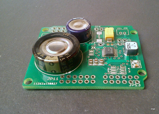
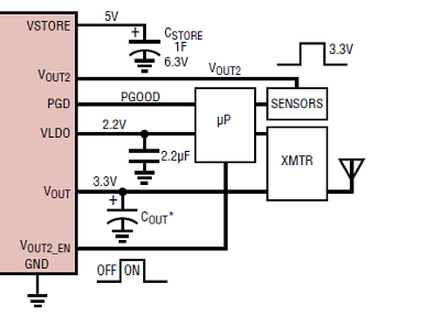
This board uses a transformer to step-up the voltage and works with voltages as low as 20mV. Here is an intended use:
There are three outputs:
Vout
Vout2 and
VLDO
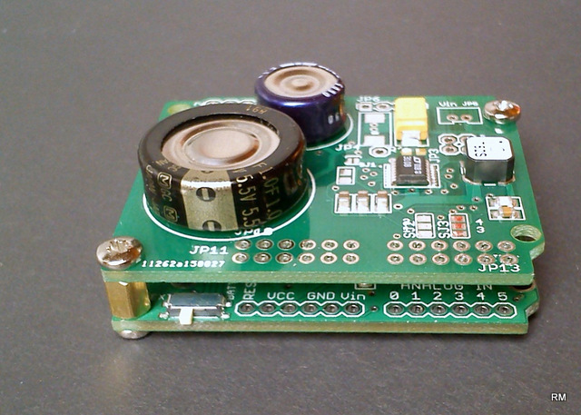
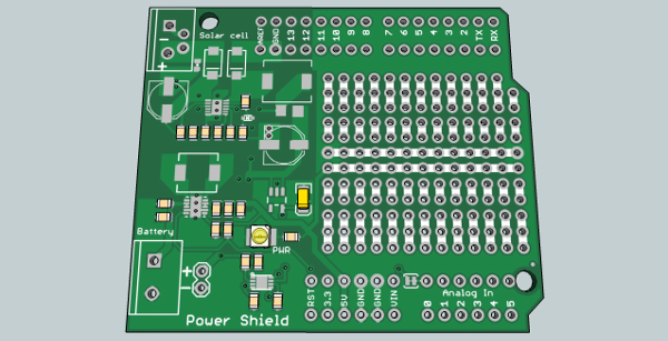
Vout and VLDO turn on as soon as the voltage on those pins is within regulation and Vout2 turns on when the Vout2_EN signal receives a high on its pin from a microcontroller, for example.And the second one is a Solar Energy Harvester which is powered by a small 5 - 20V solar cell:
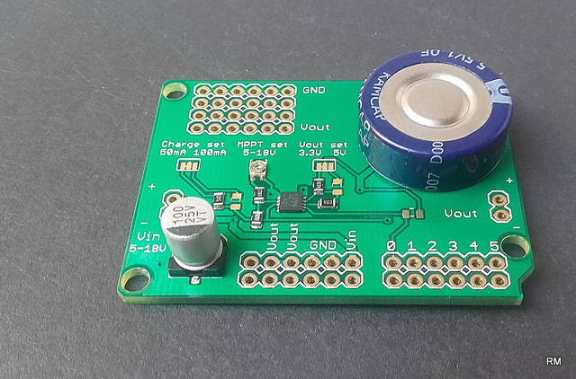
The IC can operate with up to 60V of input voltage and has a built-in CC and CV algorithm.
There are also some settings available for this one:
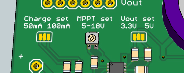
User can choose output voltage and charge current and also MPPT point of solar cell.
This power supply can act as a battery charger as well.Both boards are designed to fit on top of sensor board:
to help with connections -
Hello,
Just an idea, an interresting boardd would be the one to have an efficient management of battery and solar panel for arduino projects, such as the one on the ceech board but for arduini.
I would say it would be most helpful for Particle.io projects too for they propose something to small IMHO.
-
Here is the link to design files: https://github.com/ceech
-
Amazing product. We can have sensors like enocean with mysensors !
With Sensebender, can we send data every minutes with your energy harvester ? -
@ceech said:
@epierre I'm working on it. The board is finished, just needs a test.
Here is a link to the particle one: https://docs.particle.io/datasheets/photon-shields/#power-shield
certainly a solar panel is quite big, but if it would fit in the solar lamp shown elsewhere, it would be very useful to provide an exterior packaging with solar panel.
-
How fast do the capacitors self drain at night? I tried some quick measurements a Maxwell super capacitor, and it seemed to lose a lot of its charge just sitting still with nothing connected to it. Are there any super capacitors that are known to hold on to their charge quite well?
-
Interesting stuff! Under what license do you work? I an only asking because I think energy harvesters would be a good concept for MYSX daughter boards. You are welcome to consider it for your design, or you can let me have a stab at a reshuffled board for MYSX use. I could not find the boards on github, but I don't have eagle installed either, so they are probably inside one of the other boards there.
If you are unfamiliar with MYSX, there is a specification. -
How fast do the capacitors self drain at night? I tried some quick measurements a Maxwell super capacitor, and it seemed to lose a lot of its charge just sitting still with nothing connected to it. Are there any super capacitors that are known to hold on to their charge quite well?
@NeverDie One of the problems is the charge/discharge curve:
As you can see the capacitor loses a lot of its charge in the moments right after it starts discharging. It holds the bottom half of the charge better. They are useful for short pulses of energy. But they are not batteries by any means.Source: http://www3.ncc.edu/faculty/ens/schoenf/ELT115/UCC.html
And the other is an improper measurement. The multimeter draws current from capacitor. Anyway here is a graph of self discharge rates by capacitor type:
Source: http://www.robotroom.com/Capacitor-Self-Discharge-1.html
-
Interesting stuff! Under what license do you work? I an only asking because I think energy harvesters would be a good concept for MYSX daughter boards. You are welcome to consider it for your design, or you can let me have a stab at a reshuffled board for MYSX use. I could not find the boards on github, but I don't have eagle installed either, so they are probably inside one of the other boards there.
If you are unfamiliar with MYSX, there is a specification.@Anticimex I'm familiar with mysensor boards and the thought had crossed my mind. I'll do it, I just haven't come around to take the time, yet.
-
Interesting stuff! Under what license do you work? I an only asking because I think energy harvesters would be a good concept for MYSX daughter boards. You are welcome to consider it for your design, or you can let me have a stab at a reshuffled board for MYSX use. I could not find the boards on github, but I don't have eagle installed either, so they are probably inside one of the other boards there.
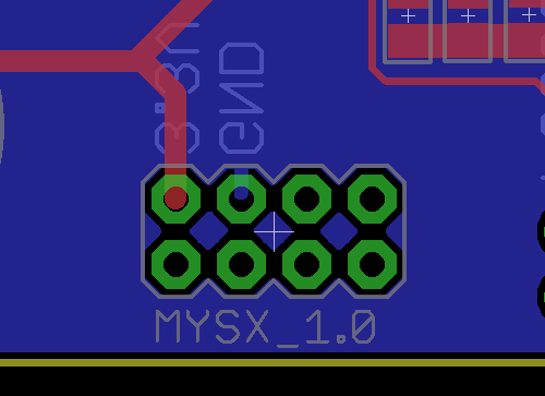
If you are unfamiliar with MYSX, there is a specification.@Anticimex I'm trying to create a harvester board with MYSX_1.0 connector on it. I think I got the position requirements figured out but I'm not sure I understand the connections that are supposed to be present. I got the GND and 3,3V, how about the others? Can you point me in the right direction? Here is what i got so far:
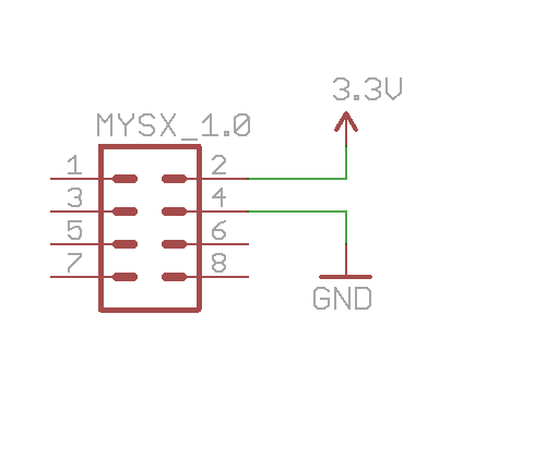
Thanks.
-
@Anticimex I'm trying to create a harvester board with MYSX_1.0 connector on it. I think I got the position requirements figured out but I'm not sure I understand the connections that are supposed to be present. I got the GND and 3,3V, how about the others? Can you point me in the right direction? Here is what i got so far:
Thanks.
@ceech well, if you do a board that supplies power, you should use the Vraw signal, because that would be where "motherboards" expect incoming power. 3.3V are typically supplied by the motherboard. So if your subboard is a supplier, it should feed on Vraw. You can see my schematic for a motherboard reference. Also remember when you mount MYSX on a subboard the connector has to go on the reverse side but with the top side footprint to map the pins correctly with the host.
-
@ceech well, if you do a board that supplies power, you should use the Vraw signal, because that would be where "motherboards" expect incoming power. 3.3V are typically supplied by the motherboard. So if your subboard is a supplier, it should feed on Vraw. You can see my schematic for a motherboard reference. Also remember when you mount MYSX on a subboard the connector has to go on the reverse side but with the top side footprint to map the pins correctly with the host.
@Anticimex After looking at the schematic of the board I think its power consumption exceeds the capabilities of a typical harvester power supply and I'm having second thoughts about it. It is probably not appropriate to be used with it. I might just make it for Sensebender Micro.
-
@Anticimex After looking at the schematic of the board I think its power consumption exceeds the capabilities of a typical harvester power supply and I'm having second thoughts about it. It is probably not appropriate to be used with it. I might just make it for Sensebender Micro.
@ceech I fully understand that your board won't handle that particular board. I only referenced it as an example on how a motherboard would manage the power rails in the MYSX connector. So don't be disencouraged by my specific take on a motherboard :)
-
Here are two new boards. Their purpose is to replace batteries in wireless sensor nodes in places where batteries are not appropriate, available or recommended for use.
The first one is a Thermal Energy Harvester which uses thermopile or thermoelectric generator as a power source:
This board uses a transformer to step-up the voltage and works with voltages as low as 20mV. Here is an intended use:
There are three outputs:
Vout
Vout2 and
VLDO
Vout and VLDO turn on as soon as the voltage on those pins is within regulation and Vout2 turns on when the Vout2_EN signal receives a high on its pin from a microcontroller, for example.And the second one is a Solar Energy Harvester which is powered by a small 5 - 20V solar cell:
The IC can operate with up to 60V of input voltage and has a built-in CC and CV algorithm.
There are also some settings available for this one:
User can choose output voltage and charge current and also MPPT point of solar cell.
This power supply can act as a battery charger as well.Both boards are designed to fit on top of sensor board:
to help with connections@ceech Nice Design, but you use a chip he is to expensive 4-6 Euro. Hmm, you now a alternative for this LTC4709?
Hello! It looks like you're interested in this conversation, but you don't have an account yet.
Getting fed up of having to scroll through the same posts each visit? When you register for an account, you'll always come back to exactly where you were before, and choose to be notified of new replies (either via email, or push notification). You'll also be able to save bookmarks and upvote posts to show your appreciation to other community members.
With your input, this post could be even better 💗
Register Login