My Slim 2AA Battery Node
-
Thanks for the detailed information about this project! I was/am looking for a similar solution to check whether doors are opened or closed.
Have you ever considered drilling a hole in the top of the door, and placing the entire node inside this drilled hole like the video below? Similar to this video?
That was something I planned to do, but your solution seems really nice as well in case drilling a hole in the door doesn't work out as expected.
-
I see u don't use a external 8mhz quarz. Because any technical reasons (=low current?) or for reasons of space?
-
@m26872 Great design, did you share the design on dirtyPcb's?
-
@aproxx I've never thought about it, but I think it's an excellent idea for some situations.
-
@AWI No, but the Eagle files are attached above. I'm new to all this open hw/sw sharing. You're very welcome to tell me how I should do it the right way. PM if you like.
-
@m26872 When you check out your order you can set the "sharing" options:
and even get a small profit (or a donation to MySensors..)
-
@m26872: very nice idea
just a little question, is your cable duct pvc. I think so. Alloy maybe would not be great for radio...
yoyur idea can be very helpful thx for share.
-
@scalz Yes, it's pvc.
-
@Harrdy said:
I see u don't use a external 8mhz quarz. Because any technical reasons (=low current?) or for reasons of space?
Low power, low cost, less space, less work. Stability might be an issue at different ambient temperatures etc.
-
Added a boardhouse link if anyone would like to order the board straight from there (thx @AWI). Couldn't see any cons.
I think it's enough tested, but personally I'd wait for a tested v2.0 or make suggested improvements myself first.
-
Hi,
great job! I think i will use your board to for small window -sensors.
But one question: i cannot upload sketches via arduino-ide when the 1mhz bootloader is flashed. i checked the wires and everything else and i tested a 8mhz/internal bootloader - works fine. but the 1mhz-bootloader just does not accept uploads?
-
@ahhk There's also the precompiled bootloader for 4800 baud in the link above. Did you try that one too? I think 9600 baud was maximum serial speed at 1MHz. Lower should be safer.
Or what do you mean with "does not accept uploads"? Is it locked?
Double checked boards.txt settings?
-
Hi,
i can upload via RX/TX with arduino IDE with the 8mhz/internal bootloader. but if i flash the 1mhz bootloader from the link above (atmega328_1a.hex), i cannot upload the same way...
TX/RX is connected correctly. I can upload a sketch via "Upload with programmer" and receive and transmit characters with 9600baud. tested with the example-sketch "SerialEvent".
IT is a brand new 328P - not locked...
boards.txt shows
############################################################## apm96.name=APM Optiboot internal 1MHz noBOD 9600baud apm96.upload.tool=avrdude apm96.upload.protocol=arduino apm96.upload.maximum_size=32256 apm96.upload.speed=9600 apm96.bootloader.tool=avrdude apm96.bootloader.low_fuses=0x62 apm96.bootloader.high_fuses=0xde apm96.bootloader.extended_fuses=0x07 apm96.bootloader.path=optiboot_v50 apm96.bootloader.file=atmega328_1a.hex apm96.bootloader.unlock_bits=0x3F apm96.bootloader.lock_bits=0x2F apm96.build.mcu=atmega328p apm96.build.f_cpu=1000000L apm96.build.core=arduino apm96.build.variant=standard ##############################################################
i didnt try the 4800baud bootloader until now....i will do now...
-
@ahhk Reset issue? Maybe try other startup times (low fuse 42h or 52h), other usb2serial or adjust reset R and C.
-
For info. I've prototyped and ordered a slightly improved version of the pcb. Note that this is UNTESTED and experimental.
Eagle brd-file and board house link. Use it for inspiration. Don't expect it to be and tested until next month at least.
-
Great work @m26872
Thanks for sharing!
-
Really great idea @m26872 !!
I'm waiting for the V1.2 test and review before ordering some boards on DirtyPcb.
One Tip/question : have you thought on panelizing your slimnode, because we could easily fit 3 board on the 5X5 limitation ? I also think that DirtyPCB would even process the break routing to ease board separation.
-
@frenchclem
AAMOF I ordered a panelized version just a few days ago. I'm completely new to all this, so I leave no guarantees...
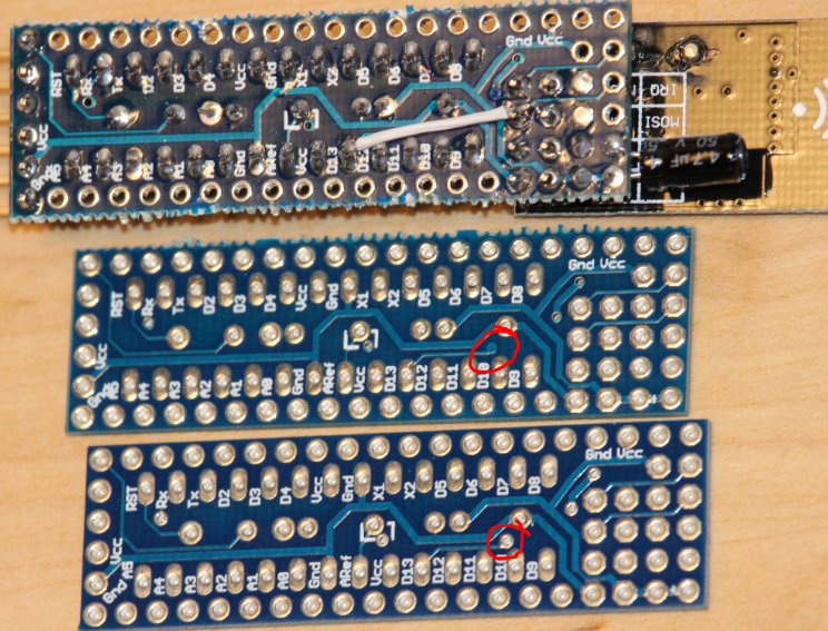
Here's the brd-file.Edit 3/12: Boardhouse link removed (the panelized version of v1.2 contains a faulty via between D13 and SCK.)
-
I guess if you ordered panelized version, you have tested the V1.2 ? Would you mind sharing the schematics also please ?
I'm also very new to this, I've never ordered PCB on Dirtypcb, how long does it takes to arrive in Europe ?
-
Delivery times depend mostly on shipping time. DirtyPCB have their boards made usually within a week after uploading the files. But shipping can take 3-4 weeks to get to Europe.
-
@frenchclem
No I actually ordered before I got the first sample, due to the delivery time. But now (just a day after) I got the first v1.2. Delivery time was 4 weeks (to Sweden). Soon tested...I don't think there are any changes to the already published schematics.
-
@GertSanders @m26872
Thanks guys for the good work I just ordered your boards
Will definitely let you know how things goesGertSanders, did you find a nice box for your board + battery ?
-
@frenchclem Not yet, the height is indeed the limiting factor. I'm now looking for a small box that can hold the sensor on it's side. SO for the moment the sensors are scattered around the house without a box around them (usually in places where the cat does not go or could find them).
-
@GertSanders thats what I was worried about. What is the height of the sensor + battery ?
-
@frenchclem
I can not measure that now (at work), but I guess around 35mm if batteries are mounted on he bottom. By using the extrnal (JST connector) power option, the height of PCB, processor and radio is around 22mm I think.Most boxes have an internal clearance of around 20-25mm.
Some boxes have 40mm internal clearance and are good in height, but those are usually also to long and wide for my taste.@m26872 's board certainly is lower, since batteries are not on the bottom but in the axis of the board. The radio is also directed away from the processor on his board, so it can be mounted lower (directly on PCB instead of on a header). I really like that concept, since it will fit the plastic cableducts made by Legrand:
http://www.ecataleg.be/fr/categorie/3020/moulure-et-goulotte-murale-en-pc-abs-sans-halogene
-
@frenchclem
Just to confirm: 35mm is the height with the small radio.
Using the larger radio (with PA+LNA) you need 41mm height
Without battery holders, and the small radio, the height is 22 mm
Width is 25mm for AAA battery holders mounted, 33mm for AA battery holder, and length is 53mm (AAA batteries) and 58mm (AA batteries)
-
v1.2 tested and working. But the design of crossing R1 and C2 was a horrible choice - it's impossible to fit both nicely under/inside the uC socket. Perhaps possible with a 1/8W R1, but otherwise R1, C2 or both must be placed on bottom side.
Good news is that all versions and orders are OK apart from this little inconvenience.
I'll try to make a better version ASAP.
-
@m26872 I have assembled 6 boards now and am very happy with the design. I use strips as a socket for the Atmega. This leaves enough room for components under it. Also made one with SPI connector. Works perfect! Thank you for sharing the design and instructions.
-
@AWI Great idea with the strips! And thanks for verifying (v1.2?).
-
I've now ordered yet another prototype version (1.4):
http://dirtypcbs.com/view.php?share=13310&accesskey=58c87fe605eb91958938f70b5efc8629Eagle brd-file.
Photo here.
-
I bought a few enclosures... "mini trunking" seems to be the correct term. This time it was ABS and a little more clear white colour and glossy finish. I think I spent around 2hrs cutting them nicely into >200pcs. 50% 23cm and 50% 19cm lengths.
-
You want to make your town mysensors
-
@m26872
200pcs!! What the heck are you up to?
-
@m26872 I think I used version 1.1? Did you change any of the wiring in the newer versions?
-
@hek
hehe, I had a hunch it'd be spectacular. Let's just say that I aim to have a few single sensor/purpose sleeping nodes, but probably not 200. At least not in a while.
-
@AWI Ops sorry, I meant v1.0. I see the larger pads in your pics. The routing is a little different to 1.2 and 1.4. Mostly related components under the uC.
-
Very nice design. Any video on installation of bootloader with various settings described in the original post?.
-
@ar91 Thx. Sorry no. I don't know of any and I'm too shy to do it myself.
-
Great idea using this housing.
Why didn't you use CR batteries to decrease size ?
http://www.digikey.com/product-detail/en/CR1220/P033-ND/269740
-
2AA batteries have approximately 2000mAh capacity. CR1220 has 35mAh. So for the same capacity, more than 50 CR1220 would be needed. That wouldn't save space
But CR1220 has lower self-discharge so they can be a good alternative for things that are really low-power, or don't need long battery life.
-
@ahmedadelhosni I've read a few reports from people with radio module issues after some time on CR "coin cell" batteries. The expected battery life time then doesn't match the result. I think you can find references by searching.
-
m26872, I just wanted to say thank you for your work on this project and for sharing it with everybody.
I've just ordered the ATMEGAs to build 5 nodes.
How confident are you about the V1.4 PCB ? If you don't see any issue with them at this point I think I'll take the whopping $14 risk
-
Aha..now I understood the reason. Thanks
-
@martkrui I'm not confident until I've tested one, but usually errors can be fixed with some ugly mods if necessary.
BTW I added to the info that any/every DirtyPCB money from this share will be donated to MySensors.org.
-
Like the board and ordered it. Can you also post exactly the capacitor types? Keep up the good work.
-
I also ordered the PCBs (at my own risk) and some of "TMK-T20 20mm 17mm"
I'll try to CNC or 3Dprint some endcaps or something.
-
@betonishard There aren't any exact values or types, but good start would be
Near the radio supply: One radial electrolytic >=4.7uF >=10V capacitor together with one ceramic (range 1pF - 1uF. I use different.).
The rest (C1, C2, C3): 0.1uF ceramic, where the value probably matters most for C2 (the Reset capacitor)
-
@m26872
Thanks... Maybe it is answered, but I didn't quite catch it. 3v will be fed to the radio, but isn't the 3.3 important instead of 3v? I don't see any stepup. Is your range acceptible?Thanks...
-
The radio can handle as low as 1.9V (source)
-
I have had a node sending messages as low as 1.65V
-
@mfalkvidd @GertSanders Thanks for your answers!! How about the range, I know it is depending on the quality of Chinese products, however can you give an estimate regarding your setups?
-
Short answer: Expect about the same range as a regular wifi card.
Long answer: Look at these informative and quite entertaining videos:
Ultimate nRF24L01 range comparison
nRF24L01 range test (arduino)
nRF24L01 range test part 2 (arduino)
-
I was about to order the 1.4v of your board before that i wanted to ask you a basic question, do i need to use any step up regulator to connect any 5v sensors? Have you connected any 5v sensors, if yes could you please post some pictures?
Thanks again for the great work.
-
You will indeed need to use a step-up regulator to use 5V sensors, as his board is 2AA battery based (gives maximum 3.2V on fresh batteries). For quite some sensors, you will find 3V3 versions, which can work at even lower voltages. look for sensors which work down to 1.8V-1.9V
Using 5V sensors in a battery based node is not efficient.
-
@GertSanders Thank you so much. Is there a recommended list of low voltage sensors? The Mysensor store only has 5v sensors i believe. I will other search other forum post as well. If anyone know from top of their head please list it.
Temperature sensor - ?
Humidity sensor - ?
Luminosity sensor - ?
PIR - ?
Infrared sensor -?
Soil Moisture sesnor -?
-
I also was about to order the 1.4 board. But are there any list of components that I need to complete the board?
-
@Cliff-Karlsson Sorry for late reply. I've not yet a BOM. I'll try o fix it later.
-
NEWS:
- A "final" version 2.0 redesigned i KiCad (very similar layout), panelized, ordered and tested OK.
- A faulty via was introduced during panelization of v1.2, so the panelized v1.2 (blue board) needs a small fix to work.
More info ASAP.
Edit 4/11: There seems to be no issues with v1.4 (red board) as I thought first. Luckily since it's now been shared a few times.
-
@m26872 I received the boards yesterday. Can you direct me to the fix needed.?
-
@AWI It should be easy the see the via with a missing hole. A connecting wire between Arduino D13 and nRF SCK is needed.
-
@m26872 Tnhx, however my samples seems to be correct...
-
@AWI Mine too. I didn't see the red v1.4 until I got it today. Looks promising, but I've not tested it yet. Interesting to see that they've done a different panelizing.
-
I've now tested v1.4 (red board) and it's working good in my MyS-net.
I can see that it has been shared 12 times at DirtyPCB, but don't know how I can see any money as suggested? As soon as I see any they'll be sent to MySensors.org.
Edit: Seems that I had a missing confirmation of my Paypal account. I'll try to solve this...
-
I decided to start learning KiCad instead of Eagle and that a tidy redesign of the Slim Node board would be a good start. Now when the red v1.4 board turned out to be quite ok (apart from the references R1,R2, R3, etc, as you can see above), I guess one can choose v1.4 or v2.0 by colour or by documentation. The v1.4 wasn't very well documented since I never really learned Eagle very good. I think that's improved now with v2.0. I've tested all the regular attributes (AVR ISP pins excluded) and it's OK.
This is my "final" version since I have a full stock of these boards for a while. If someone else want to pick up the design you're welcome.Here's all the KiCad files: MySlimNode2.0-kicad-design-doc.zip
Gerbers only in the panelized version folder.Here's a BOM (for v2.0): v2_BOM.txt
Purchase link to boardhouse (DirtyPCB). $1/order goes to MySensors.org like before.
This time it's black:
-
@m26872 Maybe you can add your info to this message (it's pinned):
http://forum.mysensors.org/topic/595/pcb-boards-for-mysensors
-
@m26872 There is something that I really can't understand.
Are the pin headers at the borders not connected to the IC pins ?
-
@ahmedadelhosni That's an important feature of this board design and one of the major diffenreces from e.g. Arduino Pro Mini. The rows of unconnected pins is like a prototyping area to mount sensors and/or other supporting components. It's easy to just fold the legs at bottom side and solder to the IC pins you want to connect to. I think you can see an example in the photos of a completed node in the first post above.
I've sized the pads so pin headers can be used there instead if desired, but then you have to connect every pin manually so that's not the primary purpose. The "Slim Node" was not just board project, but I've understood that many people enjoyed the board as a generic one, which is great.
-
@m26872 great idea indeed. You convinced me
Did you think of monitoring the voltage as this type of nodes needs this or did you leave it also as an option for us ?
-
@ahmedadelhosni you don't need additional hardware to monitor the voltage. Look for the "vcc" library. It uses the internal reference.
-
@ahmedadelhosni
... or here.
-
I received my panelized boards as well (guess 1.4). They look great!!.
I do have a question about this. Maybe it was just some silly thinking. I was trying to program the arduino 328p-pu on a regular arduino uno board (default motion sketch). After I did this I hooked it up on to the board.
However I am not receiving anything on the arduino serial monitor. I connected the arduino uno to your board. v to v, rx to rx, tx to tx, ground to ground and reset to reset. Am I just thinking to simple? Can someone please advise me to get this board up and running? I also soldered d13 additional to the nrf.
I soldered all caps, however I did not solder the resistor, is that one mandatory?
Many thanks and keep up the good work.
-
@m26872 @AWI yeah you are right. Thanks a lot.
I really consider buying the latest version. I think it is verified now to be working correctly.
-
@betonishard
If you've got red boards it's v1.4 and should not need the D13 fix. And R1 and C2 are mandatory if you want the 6 pin serial Arduino interface to work.Did you read about the necessary bootloader and fuse settings in the first post? An Atmega328p setup as standard Arduino wont work, because of Internal clock, BOD, etc. Perhaps Arduino Uno as a bootloader is good for you.
If you haven't any experience in bootloader and fuse settings, you should know that it can be a mess. A lot of things can go wrong. Nobody can walk you through it here. Look among all the existing toturials on the internet to find what is working for you and of course ask if you have any more specific questions.
-
I know I have many questions but how about inverting the nrf position by 180 degree so that it can be on top of the atmega and decrease that length. Would it fit in your design ?
Can you do such board for those who are interested like me ?
-
@ahmedadelhosni
I think it's a good idea! And an easy mod, but it's not on priority list atm. Someone else would get a quick start from my already published kicad-files.The thought behind present design is that I didn't want anything to cover the antenna in any direction, but I doubt it would matter much in this suggested case. It'll be worse when it comes to the hight. Look at the photos. The nRF becomes too high for my enclosures if I use a socket, and the 328p with its socket is too high to fit under a nRF without its socket. The solution would be to remove the 328p socket and move the R and Cs to bottom side or somewhere else. And without a 328p socket, the 3x2 AVR ISP pins would become more important to keep. Otherwise the board could have been trimmed even more.
-
@m26872 I guess the nrf above the atmega won't cause problems or interference to the atmega due to rf signals. so that's fine.
I measured the nrf and it will be 13 mm, so I thought it may fit as from the photos, I guess the max height can be 13 or 14. For me increasing the height is not a problem as I am still searching for cheap compact and not so long enclosure with maximum heigh 20 mm to use. I am searching for cheap products which are kept in that size of enclosure which I need but didn't find it yet
I didn't use Kicad before and I guess there is no converters to eagle. Youtube time
Can you please tell me the total length of the board + nrf ?
-
@ahmedadelhosni
It's 74mm with the angled Arduino pins and 69mm without.
-
@m26872 Thanks.
Hopefully this is my last question
Is V1.4 and 2.0 the same ? One is red in Eagle and the other in black in Kicad ?
If yes, could you please guide me to the eagle's project files ? Thanks.
-
@ahmedadelhosni
Yes, v1.4 is Eagle. I'll upload it later today. But it's just a brd-file. And I think I had some broken sch-brd connections even in v1.2. One reason for the KiCad design was to improve this.
-
@m26872 hmm I see. So i will begin learning Kicad today. Thanks for your effort and support
-
@ahmedadelhosni
I uploaded the brd in the v1.4 post above just for completness.
Happy Kicading! Hope you'll enjoy. I liked it a lot better. There were a few nice youtube tutorials.
You're welcome.
-
First Slim Node board donation from the DirtyPCB board share now sent. $12 to MySensors.org. Thanks to everyone that have ordered.
Later credit draw will be in probably linger a bit. DirtyPCB seems to be somewhat of a non-profit community with manual attendance to all share credits. I almost got banned in my attempts to get a reply from them. In order to show my appreciation for their great service, I plan to only request further credits in quantities of 50. If the board not's been shared in a year a so, of course I'll make an exception.
-
@m26872
Thanks for the kind donation to the MySensors project. We'll use it to develop new fun things for the community!
-
I was out of radio's, only a few "smd" types left which I mounted on the board with some patchwork
Now even more space left in the (small) housing.
-
Could u show a screen for the lockbits too? I have never set them before and need some guidance thanks
Dakky
-
@dakky Done.
-
Is this what you used to burn the bootloader?
-
I use this. Maybe not so expensive when I bought it 15 months ago, but still. I remember I was mad after I'd failed a lot with avrdude and cheaper tools (uno).
-
Just received my boards from DirtyPCB
Enough for 10x3=30 sensors... The boards look nice. I think I can even skip the R&C's if I use the internal VCC measuring method but I'll have to scan the thread for that.
-
@martkrui R1 and C2 are mandatory if you intend to use the 6 pin FTDI port (I think you do). C3 (ARef - Gnd) is primarily for when you use Adc external ref, but (if I remember correct) it stabilizes the Adc in general. C1 (Vcc - Gnd) is just the "near chip supply input capacitor" and could probably be left out if there are some other caps near the nRF.
-
@dakky said:
Could u show a screen for the lockbits too? I have never set them before and need some guidance thanks
Dakky
I use ubuntu, and a tiny USB, so after I have flashed my arduino board, I run this avrdude command, that will run until battery is low
avrdude -c usbtiny -p m328p -U efuse:w:0x07:m
I have bought usbtiny from this guy:
http://www.ebay.com/itm/USBtinyISP-V4-AVR-ISP-Programmer-Reliable-Plastic-Enclosure-/330824700564?hash=item4d06b05294
-
@m26872 Hi again. Just a small update regarding rotating the nrf.
I decided that in my designs I'll need the straight and rotated version, thus I'll design a small board to map the pin outputs like the image below. It will be above the ICSP pins but I really don't care about re flashing.
I'll order the board as soon as I finish pcb layout of some other boards and ship all at once.
Thanks.
-
@ahmedadelhosni You know that the nRF pins are not centered? That means if you rotate it like this it will no longer be straight above the "slim node motherboard".
What height do you expect it to be?
-
Another "noobish" question:
When using this bootloader, one cycle takes 8 seconds? What happens, if for example, a switch is pressed between? does this sensor detect this?
-
@dakky Plz correct me... but I guess you're talking about the Avr sleep cycles? I don't know what that's got to do with the bootloader or this thread. I think it's related to interrupt, timers, mysensors and arduino lowpower library. The sleep cycles shouldn't be something to worry about if you're using the "sleep" function as in MySensors API.
-
@m26872 hmm you're right. maybe this is a too generic question to be discussed here. pardon me.
-
I had a bit of an issue getting things going as I've never played with the fuses before. Maybe this can save someone else some time. If I'm doing something silly here please correct me.
[DISCLAIMER] this worked for me. Use at own risk[DISCLAIMER]
Executed these commands from the subfolder \hardware\tools\avr\bin of my local arduino IDE.
Connected the board ICSP using an USBASP with the latest firmware. Change the "-c usbasp" part if you connect using something else.Flash bootloader
avrdude -C ../etc/avrdude.conf -c usbasp -B5 -p ATmega328P -U flash:w:..\..\..\arduino\avr\bootloaders\atmega\atmega328_1a.hex
Set fuses
avrdude -C ../etc/avrdude.conf -c usbasp -B5 -p ATmega328P -U lfuse:w:0x62:m -U hfuse:w:0xDE:m -U efuse:w:0x07:m -U lock:w:0x2F:m
I think the B5 was crucial as it slows things down a bit. The bootloader (atmega328_1a.hex) is the one mentioned in the first post. I also added the part in the boards.txt of the arduino IDE.
Now I can connect the board to the FTDI and upload and run sketches without issues.
On to the next step
-
I am not so really skilled in transferring a wiring diagram to "real live". Is this the correct implementation for battery measuring?
-
@dakky First, the "normal" battery monitoring to this node is to use the internal method by, if you like, using the vcc library. Measuring Vcc with external voltage divider makes not a lot of sense. The external voltage divider is useful when measuring e.g. raw battery voltage to some voltage regulator.
Second, I think you've switched A0 and Gnd in your drawing.
-
hurm did i switch them?
Concerning the method: hmm ok. I just thought, that the one recommenced in the build section of mysensors should be the "correct" one.EDIT: Hrhr @Yveaux vcc lib is cute workd out of the box thx