How To - Doorbell Automation Hack
-
Hi,
Just a quick question. I'm trying the original code for the doorbell, and I have it registering in Domoticz just great,. I have two lights, one to turn off the relay and the other, not sure of (thought it would turn on if doorbell was tripped). Anyways, did I miss something or did domoticz register it as the wrong item?
Thanks,
-
@drock1985 I have mine registered as a motion sensor. So when the button is pressed it shows tripped. It will only show tripped for one second though so maybe the Domoticz UI isn't updating fast enough?
-
Been looking into this, not sure what the problem is. I changed over the motion sensor settings in Domoticz so that it would stay on for 5 seconds after being tripped, but it never registers the change. I can turn the chime itself on and off no problem, just no alert.
This is the output from serial monitor in Arduino with the doorbell sensor. The sensor acknowledges the change in switch state (for muting the chime) but doesn't for the action of the button being pushed. Doesn't appear to be a message being sent out either.
send: 7-7-0-0 s=255,c=0,t=17,pt=0,l=3,sg=0,st=ok:1.5
send: 7-7-0-0 s=255,c=3,t=6,pt=1,l=1,sg=0,st=ok:0
read: 0-0-7 s=255,c=3,t=6,pt=0,l=1,sg=0:M
sensor started, id=7, parent=0, distance=1
send: 7-7-0-0 s=255,c=3,t=11,pt=0,l=16,sg=0,st=ok:Doorbell Monitor
send: 7-7-0-0 s=255,c=3,t=12,pt=0,l=3,sg=0,st=ok:1.0
send: 7-7-0-0 s=1,c=0,t=3,pt=0,l=0,sg=0,st=ok:
send: 7-7-0-0 s=0,c=0,t=1,pt=0,l=0,sg=0,st=ok:
read: 0-0-7 s=1,c=1,t=2,pt=0,l=1,sg=0:0
Incoming change for sensor:1, New status: 0
read: 0-0-7 s=1,c=1,t=2,pt=0,l=1,sg=0:1
Incoming change for sensor:1, New status: 1 -
Well, I got it to work. Had to add a gw.send command to the code. The below is for the original 1 door chime that @petewill has created. I have added the code to make this compatible with Domoticz.
/* * The MySensors Arduino library handles the wireless radio link and protocol * between your home built sensors/actuators and HA controller of choice. * The sensors forms a self healing radio network with optional repeaters. Each * repeater and gateway builds a routing tables in EEPROM which keeps track of the * network topology allowing messages to be routed to nodes. * * Created by Henrik Ekblad <henrik.ekblad@mysensors.org> * Copyright (C) 2013-2015 Sensnology AB * Full contributor list: https://github.com/mysensors/Arduino/graphs/contributors * * Documentation: http://www.mysensors.org * Support Forum: http://forum.mysensors.org * * This program is free software; you can redistribute it and/or * modify it under the terms of the GNU General Public License * version 2 as published by the Free Software Foundation. * ******************************* * * REVISION HISTORY * Version 1.0 - PeteWill * * DESCRIPTION * This sketch is used to control a doorbell ring with a relay as well as send an * alert when the buttons is pressed. Connect the button to ground and digital * pin 3. The relay controlling the doorbell is conntected to pin 4. * * Watch the How To video here: https://youtu.be/nMIcalwpstc * * Version 1.1 - ResentedPoet * * Added gw.send command so that if doorbellDetect variable was active, it would send V_TRIPPED * to the motion sensor controlling the doorbell. Necessary for Domoticz compatibility */ #include <MySensor.h> #include <SPI.h> #include <Bounce2.h> #define NODE_ID AUTO // or set to AUTO if you want gw to assign a NODE_ID for you. #define DOORBELL_PIN 3 // Arduino Digital I/O pin number for the doorbell button #define RELAY_PIN 4 // Arduino Digital I/O pin number for the relay #define DOORBELL_CHILD_ID 0 //ID of the doorbell #define SWITCH_CHILD_ID 1 // Id of the switch that will control doorbell sound #define RELAY_ON 1 #define RELAY_OFF 0 Bounce debouncer = Bounce(); MySensor gw; MyMessage switchMsg(SWITCH_CHILD_ID, V_LIGHT); MyMessage doorbellMsg(DOORBELL_CHILD_ID, V_TRIPPED); unsigned int doorbellDelay = 1000; // interval at which to keep the doorbell button sensor triggered (milliseconds). This is used to stop people (kids) from pressing it too often unsigned int ringTime = 700; //How long the doorbell relay is on (in milliseconds) unsigned long doorbellMillis; //Used to keep track of the last doorbell button press unsigned long doorbellTimer; //Used to keep track of doorbell ring time byte doorbellPreviousVal; //Used to keep track of doorbell button pressed state boolean ringDoorbell; //Used to initiate the ring doorbell if statement boolean doorbellSound; //Used to keep track if the doorbell should sound or be silent. Value recieved from doorbell on/off switch boolean doorbellOff = true; //Used to keep track of doorbell ring state void setup() { gw.begin(incomingMessage, NODE_ID); // Send the sketch version information to the gateway and Controller gw.sendSketchInfo("Doorbell Monitor", "1.0"); // Setup the button and activate internal pull-up pinMode(DOORBELL_PIN, INPUT_PULLUP); // After setting up the button, setup debouncer debouncer.attach(DOORBELL_PIN); debouncer.interval(5); // Register all sensors to gw (they will be created as child devices) gw.present(SWITCH_CHILD_ID, S_LIGHT); gw.present(DOORBELL_CHILD_ID, S_MOTION); // Make sure relays are off when starting up digitalWrite(RELAY_PIN, RELAY_OFF); // Then set relay pins in output mode pinMode(RELAY_PIN, OUTPUT); // Set doorbellSound to last known state (using eeprom storage) doorbellSound = gw.loadState(SWITCH_CHILD_ID); } void loop() { gw.process(); unsigned long currentMillis = millis(); //Check to see if doorbell button was pushed. if (currentMillis - doorbellMillis > doorbellDelay) //used to stop doorbell from being pressed too frequently { debouncer.update(); // Read doorbell button value byte doorbellDetect = !debouncer.read();//read, then reverse the value so it will send correct trigger state to controller if (doorbellDetect != doorbellPreviousVal) { //Serial.print("doorbellDetect Value: "); //Serial.println(doorbellDetect); if (doorbellDetect == 1) { ringDoorbell = true; doorbellTimer = currentMillis; gw.send(doorbellMsg.set(doorbellDetect?"1":"0")); // Send tripped value to gw } doorbellMillis = currentMillis; doorbellPreviousVal = doorbellDetect; } } if (ringDoorbell) { if (doorbellSound) { if (doorbellOff) { digitalWrite(RELAY_PIN, RELAY_ON); //Serial.println("Doorbell sounded."); doorbellOff = false; } else { if (currentMillis - doorbellTimer > ringTime) { ringDoorbell = false; digitalWrite(RELAY_PIN, RELAY_OFF); //Serial.println("Doorbell off."); doorbellOff = true; } } } } } void incomingMessage(const MyMessage & message) { // We only expect one type of message from controller. But we better check anyway. if (message.isAck()) { Serial.println("This is an ack from gateway"); } if (message.type == V_LIGHT) { // Change relay state doorbellSound = message.getBool(); // Store state in eeprom gw.saveState(SWITCH_CHILD_ID, doorbellSound); // Write some debug info Serial.print("Incoming change for sensor:"); Serial.print(message.sensor); Serial.print(", New status: "); Serial.println(message.getBool()); } } -
This is the output from Serial Monitor now on the doorchime controller.
req id
send: 255-255-0-0 s=255,c=3,t=3,pt=0,l=0,sg=0,st=ok:
read: 0-0-255 s=255,c=3,t=4,pt=0,l=1,sg=0:8
send: 8-8-0-0 s=255,c=0,t=17,pt=0,l=3,sg=0,st=ok:1.5
send: 8-8-0-0 s=255,c=3,t=6,pt=1,l=1,sg=0,st=ok:0
read: 0-0-8 s=255,c=3,t=6,pt=0,l=1,sg=0:M
id=8
send: 8-8-0-0 s=255,c=0,t=17,pt=0,l=3,sg=0,st=ok:1.5
send: 8-8-0-0 s=255,c=3,t=6,pt=1,l=1,sg=0,st=ok:0
read: 0-0-8 s=255,c=3,t=6,pt=0,l=1,sg=0:M
sensor started, id=8, parent=0, distance=1
send: 8-8-0-0 s=255,c=3,t=11,pt=0,l=16,sg=0,st=ok:Doorbell Monitor
send: 8-8-0-0 s=255,c=3,t=12,pt=0,l=3,sg=0,st=ok:1.0
send: 8-8-0-0 s=1,c=0,t=3,pt=0,l=0,sg=0,st=ok:
send: 8-8-0-0 s=0,c=0,t=1,pt=0,l=0,sg=0,st=ok:
send: 8-8-0-0 s=0,c=1,t=16,pt=0,l=1,sg=0,st=ok:1
send: 8-8-0-0 s=0,c=1,t=16,pt=0,l=1,sg=0,st=ok:1
read: 0-0-8 s=1,c=1,t=2,pt=0,l=1,sg=0:1
Incoming change for sensor:1, New status: 1
send: 8-8-0-0 s=0,c=1,t=16,pt=0,l=1,sg=0,st=ok:1
send: 8-8-0-0 s=0,c=1,t=16,pt=0,l=1,sg=0,st=ok:1
read: 0-0-8 s=1,c=1,t=2,pt=0,l=1,sg=0:0
Incoming change for sensor:1, New status: 0
send: 8-8-0-0 s=0,c=1,t=16,pt=0,l=1,sg=0,st=ok:1
send: 8-8-0-0 s=0,c=1,t=16,pt=0,l=1,sg=0,st=ok:1
send: 8-8-0-0 s=0,c=1,t=16,pt=0,l=1,sg=0,st=ok:1
send: 8-8-0-0 s=0,c=1,t=16,pt=0,l=1,sg=0,st=ok:1
read: 0-0-8 s=1,c=1,t=2,pt=0,l=1,sg=0:1
Incoming change for sensor:1, New status: 1
send: 8-8-0-0 s=0,c=1,t=16,pt=0,l=1,sg=0,st=ok:1
send: 8-8-0-0 s=0,c=1,t=16,pt=0,l=1,sg=0,st=ok:1 -
So got my doorbell up and working. Here's the details: I used the mini RBoard and it's working out great.
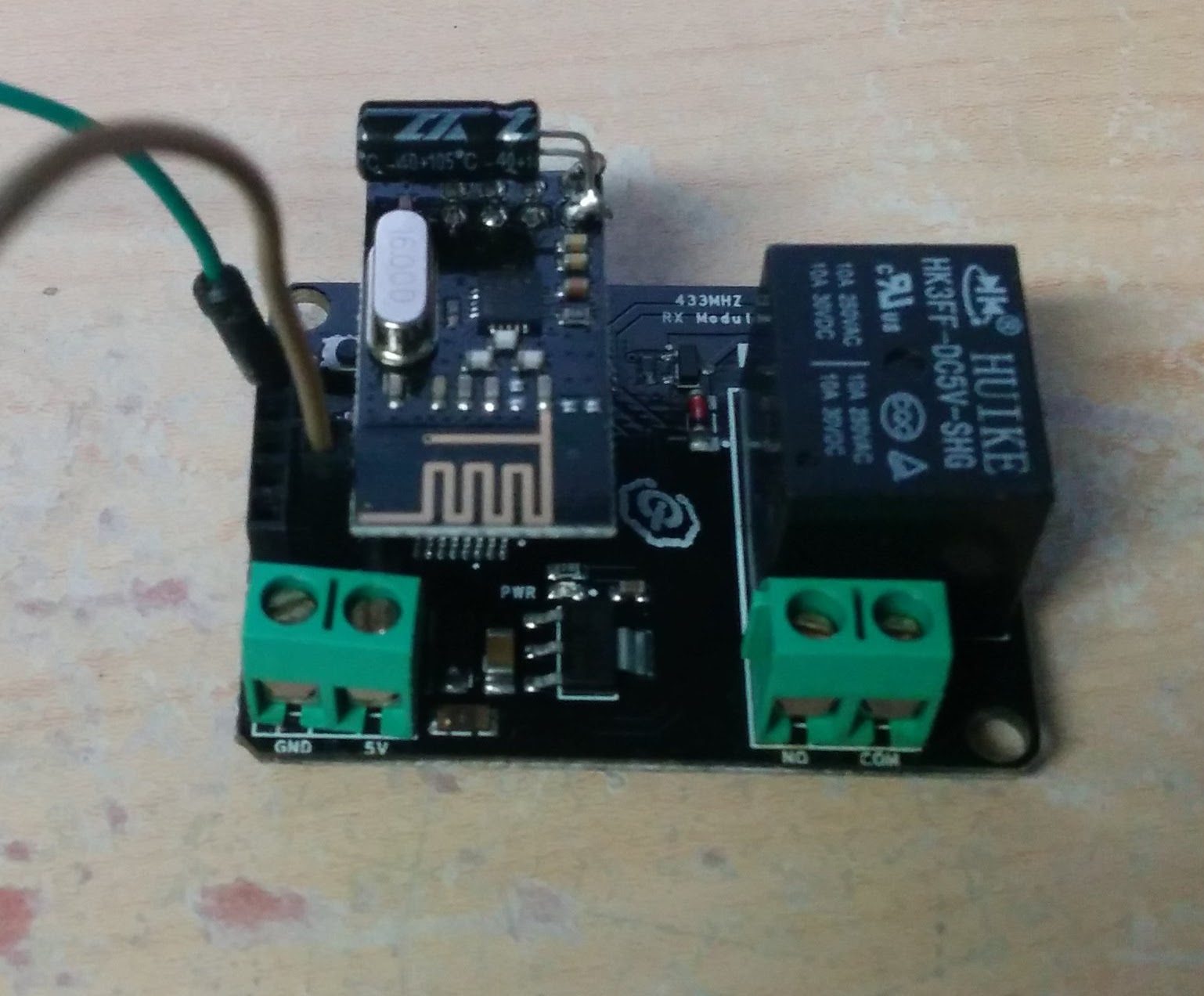
I soldered the cap directly onto the nrf board. Unfortunately, that board overhangs the A0 connections on the rboard (there's 2 pins there, one is the A0 pin and one is a ground). Thankfully, it only ACTUALLY covered the ground, so it was easy to work around. The brown wire in the photo is the wire I have connected to the A0 pin. The green wire is a temp wire I was connecting to the ground in the serial connections.
In the doorbell, I cut away one of the panels over one of the resonant chambers since I saw that the module would fit in there perfectly. I then wired it up and tucked it away. I did lose a little volume since the chamber is filled rather than resonating, but it's worth it to have the doorbell notifying my Vera system. That can flash lights and so forth to notify us other ways - we couldn't usually hear the doorbell when downstairs anyway.
Code wise, I used the original code above with just a couple minor changes. I set the doorbell_pin to A0, the relay_pin to 4, and the node_ID to auto. I also set it to act as a repeater since it's hardwired to power. Now that I have it working, I wish I'd changed the ringTime to a lower value since 7/10 of a second is way longer than the doorbell normally takes between the two notes, but it's not a big deal. Not worth pulling the board out, disconnecting it, reprogramming it, and reinstalling everything :-)
-
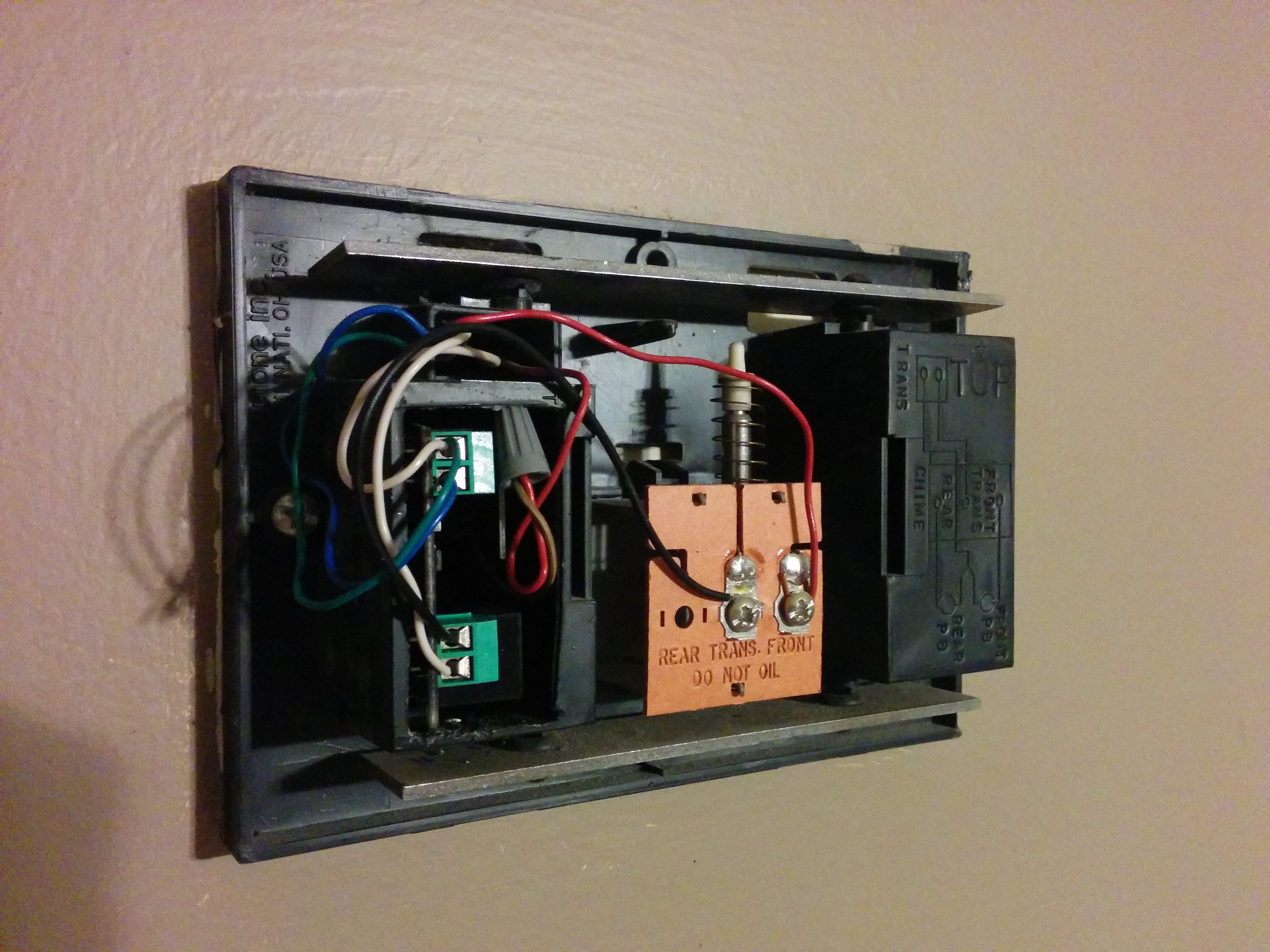
My wiring:
I discovered that they ran 4 conductor wire from the transformer in the basement to this location. So I plugged a phone charger in near the transformer, cut the end off a USB cable, and connected the 5V and gnd wires from that USB cable to the spare 2 wires in the cable. So then there's 6 wires coming into the doorbell as shown here: 2 for 16VAC from the transformer, 2 for 5VDC from the phone charger, and 2 from the doorbell button. I then connected the 5V pair to the top pair of screw terminals in the photo on the rboard. They're the blue and green wires. The white wire in the top terminal is one side of the button, connecting to ground there. The second side of the button is the red wire going into the grey wire nut. The brown wire coming out of the nut connects to the A0 pin on the board. Finally, the 2 16VAC wires are red and white. The red goes over to the right terminal on the plunger mechanism. The white goes to the common terminal on the rboard's relay connections. Finally, a black wire connects the NO from the relay to the other side of the plunger.
Hopefully that was all clear for anyone wanting to wire up their own!
-
Hello all,
I'm trying to hook this doorbell sensor up, what I've found is that when I connect it, I must connect it to NC. The downside is that when I reset the Arduino, the doorbell keeps ringing until pin4 is pulled up. How can I change that in the sketch?
Also I can ring it once, it rings and then it stops working. Connection to the gateway is lost and it won't ring either.
been trying to fix it for 3 days now, but I can't seem to figure out what I've done wrong.
Hooked up pin 4 to the input pin of the relay. The relay is directly powered by 5v coming from a usb hub with 2A.
The Arduino is powered using the same 5V, with a regulator to the radio to give it 3.3V. Connected a 4.7uF cap directly on the radio.
When I reset the arduino this comes to the gateway:0;0;3;0;9;read: 16-16-0 s=255,c=0,t=17,pt=0,l=3,sg=0:1.5 0;0;3;0;9;read: 16-16-0 s=255,c=3,t=11,pt=0,l=16,sg=0:Doorbell Monito 0;0;3;0;9;read: 16-16-0 s=255,c=3,t=12,pt=0,l=3,sg=0:1.0 0;0;3;0;9;read: 16-16-0 s=1,c=0,t=3,pt=0,l=0,sg=0: 0;0;3;0;9;read: 16-16-0 s=0,c=0,t=1,pt=0,l=0,sg=0: 0;0;3;0;9;read: 16-16-255 s=255,c=3,t=7,pt=0,l=0,sg=0: 0;0;3;0;9;send: 0-0-16-16 s=255,c=3,t=8,pt=1,l=1,sg=0,st=fail:0I can connect perfectly to the gateway using MyMQTT on Android so I think it is failing on the side of the doorbell any help would be greatly appreciated!
-
For the NC problem change:
#define RELAY_ON 1
#define RELAY_OFF 0
to:
#define RELAY_ON 0 #define RELAY_OFF 1 -
Hello all,
I'm trying to hook this doorbell sensor up, what I've found is that when I connect it, I must connect it to NC. The downside is that when I reset the Arduino, the doorbell keeps ringing until pin4 is pulled up. How can I change that in the sketch?
Also I can ring it once, it rings and then it stops working. Connection to the gateway is lost and it won't ring either.
been trying to fix it for 3 days now, but I can't seem to figure out what I've done wrong.
Hooked up pin 4 to the input pin of the relay. The relay is directly powered by 5v coming from a usb hub with 2A.
The Arduino is powered using the same 5V, with a regulator to the radio to give it 3.3V. Connected a 4.7uF cap directly on the radio.
When I reset the arduino this comes to the gateway:0;0;3;0;9;read: 16-16-0 s=255,c=0,t=17,pt=0,l=3,sg=0:1.5 0;0;3;0;9;read: 16-16-0 s=255,c=3,t=11,pt=0,l=16,sg=0:Doorbell Monito 0;0;3;0;9;read: 16-16-0 s=255,c=3,t=12,pt=0,l=3,sg=0:1.0 0;0;3;0;9;read: 16-16-0 s=1,c=0,t=3,pt=0,l=0,sg=0: 0;0;3;0;9;read: 16-16-0 s=0,c=0,t=1,pt=0,l=0,sg=0: 0;0;3;0;9;read: 16-16-255 s=255,c=3,t=7,pt=0,l=0,sg=0: 0;0;3;0;9;send: 0-0-16-16 s=255,c=3,t=8,pt=1,l=1,sg=0,st=fail:0I can connect perfectly to the gateway using MyMQTT on Android so I think it is failing on the side of the doorbell any help would be greatly appreciated!
@arjen That's strange. You shouldn't need to connect it to NC. That means you are normally sending power to your doorbell unless it is rung. Are you sure you have the wires from your doorbell correct? You may want to double check them with a multimeter.
-
Just to make sure I've took some photo's.
When I take a multimeter and place it on the bottom two wires of the trafo I get zero rating.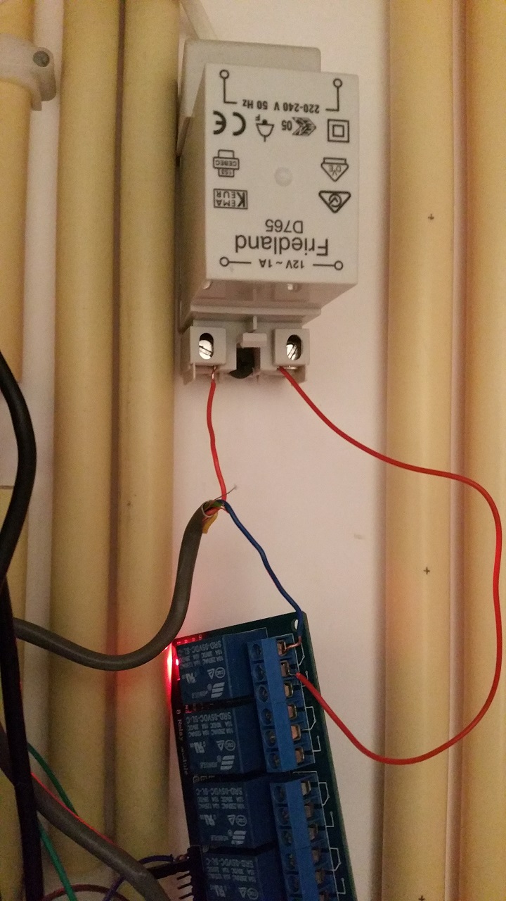
There is no difference between blue and red, neither does it make a difference if I change the wires in what ever way. Tried all possibilities I can think of. -
Yeah i know. Does it matter? It's seperated by the relay from the rest right?
Or am I saying something stupid here.... :confused: -
Sure, no prob.
This is the relay, at the moment a 6 port, didn't had a one port available.
The green wire is connected to IN1 on the relay and pin4 on the arduino.
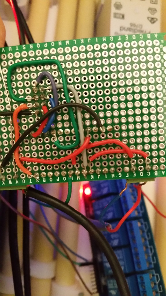
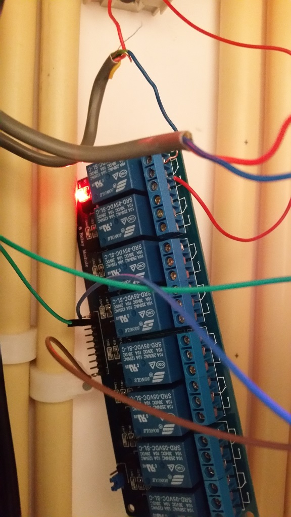
the backside of the print. The bottom row 'S' is pin 9 on the arduino, 'M' and 'K' is pin3 and Ground to doorbellbutton.
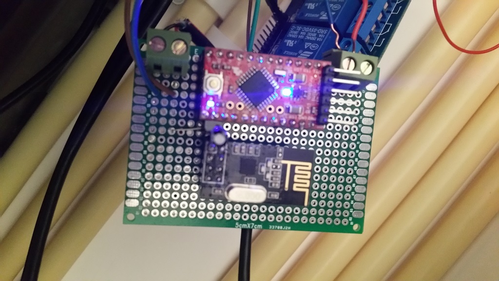
front side. The brown and blue on the left are 5V to the relay, on the right red and blue are input doorbellbutton. -
For the NC problem change:
#define RELAY_ON 1
#define RELAY_OFF 0
to:
#define RELAY_ON 0 #define RELAY_OFF 1 -
Huh, I have the same problem as @arjen is describing too, the only difference is i'm using a 2x raly vs. his 4. I don't have an issue with the relay being on, since my node is always powered on, the pull always goes high. Might just change it in the code/wiring though when I get the Arduino IDE working again.
Quick question: do you have the relay board powered by the Arduino, or another 5V source?
-
Made the changes to the sketch as suggested, and now I can connect it to NO.
Just to make sure I didn't made a mistake while soldering, used a fresh nano and made all connections again. In the sketch the changes still need to be made, however as far as i could test this morning all is working fine now!
Thanks for all the tips!The relay is powered by the same powersource as the arduino (6 port powered usb hub 2A).
Hello! It looks like you're interested in this conversation, but you don't have an account yet.
Getting fed up of having to scroll through the same posts each visit? When you register for an account, you'll always come back to exactly where you were before, and choose to be notified of new replies (either via email, or push notification). You'll also be able to save bookmarks and upvote posts to show your appreciation to other community members.
With your input, this post could be even better 💗
Register Login