How To - Doorbell Automation Hack


  • Admin

    Hi Everyone,

    I put together this quick how to video for hacking your doorbell to work with MySensors. It's pretty basic and the code is based on the Relay Actuator sketch. It has two main features: controlling if the doorbell rings with an on/off switch and sending a triggered state whenever it's pressed. The silence feature can be useful if a child (or you) is taking a nap. The triggered state can be used for many different things like starting a security camera, sending an alert or text message, playing custom sounds via Sonos or other device, etc. Another note, the doorbell will still function even if your home automation the controller is down for some reason.

    Here are the additional details:
    Arduino Doorbell Home Automation Hack with MySensors – 08:18
    — Pete B

    Fritzing Doorbell Wiring_bb.png

    /*
     * The MySensors Arduino library handles the wireless radio link and protocol
     * between your home built sensors/actuators and HA controller of choice.
     * The sensors forms a self healing radio network with optional repeaters. Each
     * repeater and gateway builds a routing tables in EEPROM which keeps track of the
     * network topology allowing messages to be routed to nodes.
     *
     * Created by Henrik Ekblad <henrik.ekblad@mysensors.org>
     * Copyright (C) 2013-2015 Sensnology AB
     * Full contributor list: https://github.com/mysensors/Arduino/graphs/contributors
     *
     * Documentation: http://www.mysensors.org
     * Support Forum: http://forum.mysensors.org
     *
     * This program is free software; you can redistribute it and/or
     * modify it under the terms of the GNU General Public License
     * version 2 as published by the Free Software Foundation.
     *
     *******************************
     *
     * REVISION HISTORY
     * Version 1.0 - PeteWill
     *
     * DESCRIPTION
     * This sketch is used to control a doorbell ring with a relay as well as send an
     * alert when the buttons is pressed.  Connect the button to ground and digital
     * pin 3.  The relay controlling the doorbell is conntected to pin 4.
     * 
     * Watch the How To video here: https://youtu.be/nMIcalwpstc
     */
    
    
    #include <MySensor.h>
    #include <SPI.h>
    #include <Bounce2.h>
    
    #define NODE_ID 16 // or set to AUTO if you want gw to assign a NODE_ID for you.
    
    #define DOORBELL_PIN  3      // Arduino Digital I/O pin number for the doorbell button 
    #define RELAY_PIN  4         // Arduino Digital I/O pin number for the relay 
    #define DOORBELL_CHILD_ID 0  //ID of the doorbell
    #define SWITCH_CHILD_ID 1    // Id of the switch that will control doorbell sound
    #define RELAY_ON 1
    #define RELAY_OFF 0
    
    Bounce debouncer = Bounce();
    
    MySensor gw;
    MyMessage switchMsg(SWITCH_CHILD_ID, V_LIGHT);
    MyMessage doorbellMsg(DOORBELL_CHILD_ID, V_TRIPPED);
    
    unsigned int doorbellDelay = 1000; // interval at which to keep the doorbell button sensor triggered (milliseconds). This is used to stop people (kids) from pressing it too often
    unsigned int ringTime = 700; //How long the doorbell relay is on (in milliseconds)
    unsigned long doorbellMillis;  //Used to keep track of the last doorbell button press
    unsigned long doorbellTimer;  //Used to keep track of doorbell ring time
    byte doorbellPreviousVal;  //Used to keep track of doorbell button pressed state
    boolean ringDoorbell;  //Used to initiate the ring doorbell if statement
    boolean doorbellSound; //Used to keep track if the doorbell should sound or be silent.  Value recieved from doorbell on/off switch
    boolean doorbellOff = true;  //Used to keep track of doorbell ring state
    
    void setup()
    {
      gw.begin(incomingMessage, NODE_ID);
    
      // Send the sketch version information to the gateway and Controller
      gw.sendSketchInfo("Doorbell Monitor", "1.0");
    
      // Setup the button and activate internal pull-up
      pinMode(DOORBELL_PIN, INPUT_PULLUP);
    
      // After setting up the button, setup debouncer
      debouncer.attach(DOORBELL_PIN);
      debouncer.interval(5);
    
      // Register all sensors to gw (they will be created as child devices)
      gw.present(SWITCH_CHILD_ID, S_LIGHT);
      gw.present(DOORBELL_CHILD_ID, S_MOTION);
    
      // Make sure relays are off when starting up
      digitalWrite(RELAY_PIN, RELAY_OFF);
      // Then set relay pins in output mode
      pinMode(RELAY_PIN, OUTPUT);
    
      // Set doorbellSound to last known state (using eeprom storage)
      doorbellSound = gw.loadState(SWITCH_CHILD_ID);
    }
    
    void loop()
    {
      gw.process();
        unsigned long currentMillis = millis();
      //Check to see if doorbell button was pushed.
      if (currentMillis - doorbellMillis > doorbellDelay) //used to stop doorbell from being pressed too frequently
      {
        debouncer.update();
        // Read doorbell button value
        byte doorbellDetect = !debouncer.read();//read, then reverse the value so it will send correct trigger state to controller
    
        if (doorbellDetect != doorbellPreviousVal)
        {
          //Serial.print("doorbellDetect Value: ");
          //Serial.println(doorbellDetect);
          gw.send(doorbellMsg.set(doorbellDetect)); 
          if (doorbellDetect == 1)
          {
            ringDoorbell = true;
            doorbellTimer = currentMillis;
          }
          doorbellMillis = currentMillis;
          doorbellPreviousVal = doorbellDetect;
        }
      }
    
      if (ringDoorbell)
      {
        if (doorbellSound)
        {
          if (doorbellOff)
          {
            digitalWrite(RELAY_PIN, RELAY_ON);
            //Serial.println("Doorbell sounded.");
            doorbellOff = false;
          }
          else
          {
            if (currentMillis - doorbellTimer > ringTime)
            {
              ringDoorbell = false;
              digitalWrite(RELAY_PIN, RELAY_OFF);
              //Serial.println("Doorbell off.");
              doorbellOff = true;
            }
          }
        }
      }
    }
    
      void incomingMessage(const MyMessage & message) {
        // We only expect one type of message from controller. But we better check anyway.
        if (message.isAck()) {
          Serial.println("This is an ack from gateway");
        }
    
        if (message.type == V_LIGHT) {
          // Change relay state
          doorbellSound = message.getBool();
          // Store state in eeprom
          gw.saveState(SWITCH_CHILD_ID, doorbellSound);
    
          // Write some debug info
          Serial.print("Incoming change for sensor:");
          Serial.print(message.sensor);
          Serial.print(", New status: ");
          Serial.println(message.getBool());
        }
      }

  • Contest Winner

    Well done. I was thinking about the same hack. So that I can have my doorbell in silent mode, if one of the neighbor kids is playing ring-my bell and run away 😉

    I like your relay solution, that's something I'm gonna do as well.


  • Admin

    @TheoL Thanks! That's a good use case too. Dang kids. 😉


  • Great hack! A simple and compact board for this would be the Mini RBoard from itead, 37mm x49mm. Just plug in a nRf.


  • That looks like a perfekt board for this Hack


  • Great How To @petewill


  • Admin

    @Dwalt Nice! Thanks for sharing. That looks like a perfect board for something like this.


  • Hardware Contributor

    FYI for anyone who wants to make a more complicated version of this, take a look at LowPowerLabs door bell controller. There is some good docs there (and in the follow up articles) if you want to try and tap the door bell power source to power the arduino. There is also a nice explanation of how to detect when another circuit activates which might be handy for another application.


  • @TD22057 This was the route I was heading with adding the doorbell to my HA, but @petewill is awesome in doing this with the video. Me and my daughter where just trying to decide what would be the best way to hack the bell. We added a Ring.com Doorbell (trial period) and trying to decide if we like it or not. The notifications are 2 way so that is nice with video and audio. But they do not have an API. I think I will try to sniff out the Motion detection or use it from my notifications to tie into my HA.


  • Hardware Contributor

    @DrJeff Very cool. I have 2 HikVision cameras covering the front of my house so I think I'm going to try the DIY version of Ring.com. Both of the cameras have "alarm" input and output wires (12V signal) that you can use to start recording video using an external PIR or do something when the camera detects motion. One camera has an external Bosch PIR sensor that works really well. It's a 12 V NC signal wire connected to the camera and it has eliminated virtually all of the false motion alarms. The other camera is above the door and has a built in PIR sensor.

    Reading this thread made me realize that I should tap into the door bell signal and the alarm output wire on the camera above to the door and send that out as a MySensor message which will send an MQTT message to a script which can grab the camera feed and email me still images (or send me a link to a web page w/ the images) of who is coming up to the house.


  • great! i am going to add this to my home domoticz! Thanks


  • Going to install one of these very soon.

    How hard would it be to modify the sketch for a two door bell system?


  • Admin

    @drock1985 Sorry for the delayed reply! It shouldn't be too hard. You will just have to create another button input and relay output in the sketch. I haven't looked at the code but you should be able to duplicate what's in there just changing the names and pins where appropriate.


  • @petewill

    Awesome, thanks.I have the parts on order, minus the power supply (will power from AA batteries for now until I get in a DC-DC step down regulator).

    Just need to find a half decent chime now. lol


  • Hey @petewill

    Started working on the project this weekend. Didn't get the parts in this week due to the holiday. Did what I could though, and I have a schematic/drawing made up for the system. This is my first drawing in fritzing, so it's a little crude. I couldn't figure out how to add a 'T' section/junction in the wire, but it all lines up for reference anyways.

    I'll start working on the Arduino code next.

    MySensors_2Door_Chime_bb.png


  • Admin

    Why don't you send over the signal wirelessly between the two doorbells?


  • Hi @hek

    I'm not too sure I understand what you are referring to. If you are referring to the buttons themselves outside being wireless, I thought about it but wasn't too sure how long a battery would last and didn't want to be changing batteries. The way I plan to do this now, I can use the existing wiring for the doorbells that are already there, and splice into the power for the door bell to power the MySensors node.

    Plus, both chimes are in the same spot, one relay sets off one set of the three contacts (Wtih a common ground I believe) and the other will chime the second.


  • Admin

    @drock1985

    Ahh. nice. Thought you might have to run some new wires around the house.


  • @hek lol, no. Just hooking up everything to the internet that I can.


  • Admin

    @drock1985 Nice! Does your doorbell use DC so you can steal power from it? I wish mine did. That would have made things easier for me. Mine uses 16VAC... 😞


  • Contest Winner

    @petewill

    Convert it!!!

    you have the power

    you have the technology

    diode bridge


  • Hey @petewill

    They vary. Some of the more expensive ones I've noticed use DC (ex play custom songs/tones), while the cheaper ones use AC.

    I built the project around the idea the wife would want something more elaborate than a simple ding sound, but I was wrong lol. So I picked up one that she looked last night, and I believe it uses AC, so I will be making a slight change to my design.

    I'll end up putting in one of these I figure, just haven't quite figured out what size smoothing capacitor I will need.

    Also, I'm not 100% sure yet (at work, hard to do research) but I may be able to get away with a simple 5v regulator once the power is converted to DC, in lieu of a variable buck converter.

    http://m.wikihow.com/Make-an-AC-DC-Converter


  • Admin

    @BulldogLowell Haha, I just took the easy way out and ran a 5V line 🙂

    @drock1985

    I built the project around the idea the wife would want something more elaborate than a simple ding sound, but I was wrong lol.

    Yeah, that's happened to me as well on other projects 🙂


  • @drock1985 said:

    I'll end up putting in one of these I figure, just haven't quite figured out what size smoothing capacitor I will need.

    Add a cap .1uf input side of the 5V regulator and a 47-220uf on the regulated 5V . High freq and a low freq ripple.

    That should do the trick same thing I was planning on doing. I bought the Ring Doorbell but still want to be notified of the actual ring into HA.


  • Hi @petewill

    I finally got the parts in to do the project. I've been working on the code, but I seem to be running into an issue. I have the four devices show up in Domoticz, but I'm not getting any feedback from the sensor. Would you mind looking at the code for me please? This is the first program I have ever worked on, and not much of a programmer mentality yet.

    /*
     * The MySensors Arduino library handles the wireless radio link and protocol
     * between your home built sensors/actuators and HA controller of choice.
     * The sensors forms a self healing radio network with optional repeaters. Each
     * repeater and gateway builds a routing tables in EEPROM which keeps track of the
     * network topology allowing messages to be routed to nodes.
     *
     * Created by Henrik Ekblad <henrik.ekblad@mysensors.org>
     * Copyright (C) 2013-2015 Sensnology AB
     * Full contributor list: https://github.com/mysensors/Arduino/graphs/contributors
     *
     * Documentation: http://www.mysensors.org
     * Support Forum: http://forum.mysensors.org
     *
     * This program is free software; you can redistribute it and/or
     * modify it under the terms of the GNU General Public License
     * version 2 as published by the Free Software Foundation.
     *
     *******************************
     *
     * REVISION HISTORY
     * 
     * 2 Door Chime
     * Version 1.0 - ResentedPoet
     * DESCRIPTION
     * Original idea/concept by PeteWill. Modified code to add second actuator (relay)
     * door chimes with 2 doors. This will allow your home automation system to differentiate
     * between front and back door. As well, this allows current 2 door chimes to still have
     * their individual chimes. Pins 3 and 4 are used for door bell 1 and relay/chime 1 
     * respectively, and digital pins 5 and 6 for door bell 2 and relay/chime 2.
     */
    
    
    #include <MySensor.h>
    #include <SPI.h>
    #include <Bounce2.h>
    
    #define NODE_ID AUTO // or set a manual ID in place of AUTO
    
    #define DOORBELL1_PIN  3      // Arduino Digital I/O pin number for the doorbell button 
    #define RELAY1_PIN  4         // Arduino Digital I/O pin number for the relay 
    #define DOORBELL1_CHILD_ID 0  //ID of the front doorbell
    #define SWITCH1_CHILD_ID 1    // Id of the switch that will control front doorbell sound
    #define RELAY1_ON 1
    #define RELAY1_OFF 0
    #define DOORBELL2_PIN  5      // Arduino Digital I/O pin number for the doorbell button 
    #define RELAY2_PIN  6         // Arduino Digital I/O pin number for the relay 
    #define DOORBELL2_CHILD_ID 2  //ID of the back doorbell
    #define SWITCH2_CHILD_ID 3    // Id of the switch that will control back doorbell sound
    #define RELAY2_ON 1
    #define RELAY2_OFF 0
    
    Bounce debouncer = Bounce();
    
    MySensor gw;
    MyMessage switchMsg1(SWITCH1_CHILD_ID, V_LIGHT);
    MyMessage switchMsg2(SWITCH2_CHILD_ID, V_LIGHT);
    MyMessage doorbellMsg1(DOORBELL1_CHILD_ID, V_TRIPPED);
    MyMessage doorbellMsg2(DOORBELL2_CHILD_ID, V_TRIPPED);
    
    unsigned int doorbellDelay = 1000; // interval at which to keep the doorbell button sensor triggered (milliseconds). This is used to stop people (kids) from pressing it too often
    unsigned int ringTime = 700; //How long the doorbell relay is on (in milliseconds)
    unsigned long doorbell1Millis;  //Used to keep track of the last front doorbell button press
    unsigned long doorbell1Timer;  //Used to keep track of front doorbell ring time
    unsigned long doorbell2Millis;  //Used to keep track of the last back doorbell button press
    unsigned long doorbell2Timer;  //Used to keep track of back doorbell ring time
    byte doorbell1PreviousVal;  //Used to keep track of front doorbell button pressed state
    byte doorbell2PreviousVal;  //Used to keep track of back doorbell button pressed state
    boolean ringDoorbell1;  //Used to initiate the ring front doorbell if statement
    boolean doorbell1Sound; //Used to keep track if the front doorbell should sound or be silent.  Value recieved from doorbell on/off switch
    boolean doorbell1Off = true;  //Used to keep track of front doorbell ring state
    boolean ringDoorbell2;  //Used to initiate the ring front doorbell if statement
    boolean doorbell2Sound; //Used to keep track if the front doorbell should sound or be silent.  Value recieved from doorbell on/off switch
    boolean doorbell2Off = true;  //Used to keep track of front doorbell ring state
    
    void setup()
    {
      gw.begin(incomingMessage, NODE_ID);
    
      // Send the sketch version information to the gateway and Controller
      gw.sendSketchInfo("2 Doorbell Monitor", "1.0");
    
      // Setup the button and activate internal pull-up
      pinMode(DOORBELL1_PIN, INPUT_PULLUP);
      pinMode(DOORBELL2_PIN, INPUT_PULLUP);
    
      // After setting up the button, setup debouncer
      debouncer.attach(DOORBELL1_PIN);
      debouncer.attach(DOORBELL2_PIN);
      debouncer.interval(5);
    
      // Register all sensors to gw (they will be created as child devices)
      gw.present(SWITCH1_CHILD_ID, S_LIGHT);
      gw.present(DOORBELL1_CHILD_ID, S_MOTION);
      gw.present(SWITCH2_CHILD_ID, S_LIGHT);
      gw.present(DOORBELL2_CHILD_ID, S_MOTION);
    
      // Make sure relays are off when starting up
      digitalWrite(RELAY1_PIN, RELAY1_OFF);
      digitalWrite(RELAY2_PIN, RELAY2_OFF);
      // Then set relay pins in output mode
      pinMode(RELAY1_PIN, OUTPUT);
      pinMode(RELAY2_PIN, OUTPUT);
    
      // Set doorbellSound to last known state (using eeprom storage)
      doorbell1Sound = gw.loadState(SWITCH1_CHILD_ID);
      doorbell2Sound = gw.loadState(SWITCH2_CHILD_ID);
    }
    
    void loop()
    {
      gw.process();
        unsigned long current1Millis = millis();
      //Check to see if front doorbell button was pushed.
      if (current1Millis - doorbell1Millis > doorbellDelay) //used to stop doorbell from being pressed too frequently
      {
        debouncer.update();
        // Read front doorbell button value
        byte doorbell1Detect = !debouncer.read();//read, then reverse the value so it will send correct trigger state to controller
    
        if (doorbell1Detect != doorbell1PreviousVal)
        {
          //Serial.print("doorbell1Detect Value: ");
          //Serial.println(doorbell1Detect);
          if (doorbell1Detect == 1)
          {
            ringDoorbell1 = true;
            doorbell1Timer = current1Millis;
          }
          doorbell1Millis = current1Millis;
          doorbell1PreviousVal = doorbell1Detect;
        }
      }
    
      if (ringDoorbell1)
      {
        if (doorbell1Sound)
        {
          if (doorbell1Off)
          {
            digitalWrite(RELAY1_PIN, RELAY1_ON);
            //Serial.println("Front Doorbell sounded.");
            doorbell1Off = false;
          }
          else
          {
            if (current1Millis - doorbell1Timer > ringTime)
            {
              ringDoorbell1 = false;
              digitalWrite(RELAY1_PIN, RELAY1_OFF);
              //Serial.println("Front Doorbell off.");
              doorbell1Off = true;
            }
          }
        }
      }
    
    //Check to see if back doorbell button was pushed.
    unsigned long current2Millis = millis();
        if (current2Millis - doorbell2Millis > doorbellDelay) //used to stop doorbell from being pressed too frequently
      {
        debouncer.update();
        // Read back doorbell button value
        byte doorbell2Detect = !debouncer.read();//read, then reverse the value so it will send correct trigger state to controller
    
        if (doorbell2Detect != doorbell2PreviousVal)
        {
          //Serial.print("doorbell2Detect Value: ");
          //Serial.println(doorbell2Detect);
          if (doorbell2Detect == 1)
          {
            ringDoorbell2 = true;
            doorbell2Timer = current2Millis;
          }
          doorbell2Millis = current2Millis;
          doorbell2PreviousVal = doorbell2Detect;
        }
      }
    
      if (ringDoorbell2)
      {
        if (doorbell2Sound)
        {
          if (doorbell2Off)
          {
            digitalWrite(RELAY2_PIN, RELAY2_ON);
            //Serial.println("Back Doorbell sounded.");
            doorbell2Off = false;
          }
          else
          {
            if (current2Millis - doorbell2Timer > ringTime)
            {
              ringDoorbell2 = false;
              digitalWrite(RELAY2_PIN, RELAY2_OFF);
              //Serial.println("Back Doorbell off.");
              doorbell2Off = true;
            }
          }
        }
      }
    }
    
      void incomingMessage(const MyMessage & message) {
        // We only expect one type of message from controller. But we better check anyway.
        if (message.isAck()) {
          Serial.println("This is an ack from gateway");
        }
    
        if (message.type == V_LIGHT) {
          // Change relay state
          doorbell1Sound = message.getBool();
          // Store state in eeprom
          gw.saveState(SWITCH1_CHILD_ID, doorbell1Sound);
    
          // Write some debug info
          Serial.print("Incoming change for sensor:");
          Serial.print(message.sensor);
          Serial.print(", New status: ");
          Serial.println(message.getBool());
        }
        
      }```

  • Contest Winner

    Haha, I just took the easy way out and ran a 5V line

    @petewill

    that may be the easy way, but not as fun 😞


  • Contest Winner

    @drock1985

    I think your code is a little hard to get through, but you need two instances of the Bounce library if you want to manage two buttons:

      debouncer.attach(DOORBELL1_PIN);
      debouncer.attach(DOORBELL2_PIN);
    

    do this instead:

    //...
    Bounce debouncePin1 = Bounce();
    Bounce debouncePin2 = Bounce();
    //...
    void setup()
    {
      //...
      debouncePin1.attach(DOORBELL1_PIN);
      debouncePin1.interval(5);
      debouncePin2.attach(DOORBELL2_PIN);
      debouncePin2.interval(5);
      //...
    }
    

    and update the state with:

    debouncerPin1.update();
    

    get it?

    alternatively you could use an array:

    Bounce debouncer[2] = Bounce();
    

    it would make your code a lot easier, but you have to understand arrays and Classes or you will be a little lost.


  • Admin

    @BulldogLowell

    that may be the easy way, but not as fun 😞

    I know huh? It seems my opportunity for fun has been getting less and less these days 😞 I still need to finish the PhoneyTV project...


  • My mini RBoard just arrived yesterday to do this... too bad I won't have any time to mess with it till probably next weekend. I'll definitely share some pics and results once I get it installed!


  • I did take a look at my doorbell last night. I have a transformer down in the basement that's outputting 16VAC. Then the doorbell upstairs, with no convenient place to get power from. The wires from both the doorbell button and the transformer come to the doorbell "box" on the wall.

    At first I was looking for a way to convert the 16VAC to 5VDC. Then as I was looking at the space in the doorbell to mount the board, I saw two more wires not connected to anything. They ran 4 conductor wire from the transformer to the bell! Sweet! So now I'll put a 5V source (probably phone charger to USB cable with the end cut off) in the basement, connect that to the other unused pair of wires, and have my power where I need it.

    Is there any issue with running the 5V DC power and the 16VAC power alongside each other? It's not like either is carrying data, so I don't think there would be...


  • Hero Member

    @timropp , If you are following the circuits posted above, the relays should provide complete isolation between 5VDC and 16VAC, so everything fine .


  • Hi,

    Just a quick question. I'm trying the original code for the doorbell, and I have it registering in Domoticz just great,. I have two lights, one to turn off the relay and the other, not sure of (thought it would turn on if doorbell was tripped). Anyways, did I miss something or did domoticz register it as the wrong item?

    Thanks,


  • Admin

    @drock1985 I have mine registered as a motion sensor. So when the button is pressed it shows tripped. It will only show tripped for one second though so maybe the Domoticz UI isn't updating fast enough?


  • @petewill

    Ah, that very well may be it. I'll investigate that end further. Thanks.


  • @petewill

    Been looking into this, not sure what the problem is. I changed over the motion sensor settings in Domoticz so that it would stay on for 5 seconds after being tripped, but it never registers the change. I can turn the chime itself on and off no problem, just no alert.

    This is the output from serial monitor in Arduino with the doorbell sensor. The sensor acknowledges the change in switch state (for muting the chime) but doesn't for the action of the button being pushed. Doesn't appear to be a message being sent out either.

    send: 7-7-0-0 s=255,c=0,t=17,pt=0,l=3,sg=0,st=ok:1.5
    send: 7-7-0-0 s=255,c=3,t=6,pt=1,l=1,sg=0,st=ok:0
    read: 0-0-7 s=255,c=3,t=6,pt=0,l=1,sg=0:M
    sensor started, id=7, parent=0, distance=1
    send: 7-7-0-0 s=255,c=3,t=11,pt=0,l=16,sg=0,st=ok:Doorbell Monitor
    send: 7-7-0-0 s=255,c=3,t=12,pt=0,l=3,sg=0,st=ok:1.0
    send: 7-7-0-0 s=1,c=0,t=3,pt=0,l=0,sg=0,st=ok:
    send: 7-7-0-0 s=0,c=0,t=1,pt=0,l=0,sg=0,st=ok:
    read: 0-0-7 s=1,c=1,t=2,pt=0,l=1,sg=0:0
    Incoming change for sensor:1, New status: 0
    read: 0-0-7 s=1,c=1,t=2,pt=0,l=1,sg=0:1
    Incoming change for sensor:1, New status: 1


  • This post is deleted!


  • Well, I got it to work. Had to add a gw.send command to the code. The below is for the original 1 door chime that @petewill has created. I have added the code to make this compatible with Domoticz.

    /*
     * The MySensors Arduino library handles the wireless radio link and protocol
     * between your home built sensors/actuators and HA controller of choice.
     * The sensors forms a self healing radio network with optional repeaters. Each
     * repeater and gateway builds a routing tables in EEPROM which keeps track of the
     * network topology allowing messages to be routed to nodes.
     *
     * Created by Henrik Ekblad <henrik.ekblad@mysensors.org>
     * Copyright (C) 2013-2015 Sensnology AB
     * Full contributor list: https://github.com/mysensors/Arduino/graphs/contributors
     *
     * Documentation: http://www.mysensors.org
     * Support Forum: http://forum.mysensors.org
     *
     * This program is free software; you can redistribute it and/or
     * modify it under the terms of the GNU General Public License
     * version 2 as published by the Free Software Foundation.
     *
     *******************************
     *
     * REVISION HISTORY
     * Version 1.0 - PeteWill
     *
     * DESCRIPTION
     * This sketch is used to control a doorbell ring with a relay as well as send an
     * alert when the buttons is pressed.  Connect the button to ground and digital
     * pin 3.  The relay controlling the doorbell is conntected to pin 4.
     * 
     * Watch the How To video here: https://youtu.be/nMIcalwpstc
     * 
     * Version 1.1 - ResentedPoet
     * 
     * Added gw.send command so that if doorbellDetect variable was active, it would send V_TRIPPED
     * to the motion sensor controlling the doorbell. Necessary for Domoticz compatibility
     */
    
    
    #include <MySensor.h>
    #include <SPI.h>
    #include <Bounce2.h>
    
    #define NODE_ID AUTO // or set to AUTO if you want gw to assign a NODE_ID for you.
    
    #define DOORBELL_PIN  3      // Arduino Digital I/O pin number for the doorbell button 
    #define RELAY_PIN  4         // Arduino Digital I/O pin number for the relay 
    #define DOORBELL_CHILD_ID 0  //ID of the doorbell
    #define SWITCH_CHILD_ID 1    // Id of the switch that will control doorbell sound
    #define RELAY_ON 1
    #define RELAY_OFF 0
    
    Bounce debouncer = Bounce();
    
    MySensor gw;
    MyMessage switchMsg(SWITCH_CHILD_ID, V_LIGHT);
    MyMessage doorbellMsg(DOORBELL_CHILD_ID, V_TRIPPED);
    
    unsigned int doorbellDelay = 1000; // interval at which to keep the doorbell button sensor triggered (milliseconds). This is used to stop people (kids) from pressing it too often
    unsigned int ringTime = 700; //How long the doorbell relay is on (in milliseconds)
    unsigned long doorbellMillis;  //Used to keep track of the last doorbell button press
    unsigned long doorbellTimer;  //Used to keep track of doorbell ring time
    byte doorbellPreviousVal;  //Used to keep track of doorbell button pressed state
    boolean ringDoorbell;  //Used to initiate the ring doorbell if statement
    boolean doorbellSound; //Used to keep track if the doorbell should sound or be silent.  Value recieved from doorbell on/off switch
    boolean doorbellOff = true;  //Used to keep track of doorbell ring state
    
    void setup()
    {
      gw.begin(incomingMessage, NODE_ID);
    
      // Send the sketch version information to the gateway and Controller
      gw.sendSketchInfo("Doorbell Monitor", "1.0");
    
      // Setup the button and activate internal pull-up
      pinMode(DOORBELL_PIN, INPUT_PULLUP);
    
      // After setting up the button, setup debouncer
      debouncer.attach(DOORBELL_PIN);
      debouncer.interval(5);
    
      // Register all sensors to gw (they will be created as child devices)
      gw.present(SWITCH_CHILD_ID, S_LIGHT);
      gw.present(DOORBELL_CHILD_ID, S_MOTION);
    
      // Make sure relays are off when starting up
      digitalWrite(RELAY_PIN, RELAY_OFF);
      // Then set relay pins in output mode
      pinMode(RELAY_PIN, OUTPUT);
    
      // Set doorbellSound to last known state (using eeprom storage)
      doorbellSound = gw.loadState(SWITCH_CHILD_ID);
    }
    
    void loop()
    {
      gw.process();
        unsigned long currentMillis = millis();
      //Check to see if doorbell button was pushed.
      if (currentMillis - doorbellMillis > doorbellDelay) //used to stop doorbell from being pressed too frequently
      {
        debouncer.update();
        // Read doorbell button value
        byte doorbellDetect = !debouncer.read();//read, then reverse the value so it will send correct trigger state to controller
    
        if (doorbellDetect != doorbellPreviousVal)
        {
          //Serial.print("doorbellDetect Value: ");
          //Serial.println(doorbellDetect);
          if (doorbellDetect == 1)
          {
            ringDoorbell = true;
            doorbellTimer = currentMillis;
            gw.send(doorbellMsg.set(doorbellDetect?"1":"0"));  // Send tripped value to gw
          }
          doorbellMillis = currentMillis;
          doorbellPreviousVal = doorbellDetect;
        }
      }
    
      if (ringDoorbell)
      {
        if (doorbellSound)
        {
          if (doorbellOff)
          {
            digitalWrite(RELAY_PIN, RELAY_ON);
            //Serial.println("Doorbell sounded.");
            doorbellOff = false;
          }
          else
          {
            if (currentMillis - doorbellTimer > ringTime)
            {
              ringDoorbell = false;
              digitalWrite(RELAY_PIN, RELAY_OFF);
              //Serial.println("Doorbell off.");
              doorbellOff = true;
            }
          }
        }
      }
    }
    
      void incomingMessage(const MyMessage & message) {
        // We only expect one type of message from controller. But we better check anyway.
        if (message.isAck()) {
          Serial.println("This is an ack from gateway");
        }
    
        if (message.type == V_LIGHT) {
          // Change relay state
          doorbellSound = message.getBool();
          // Store state in eeprom
          gw.saveState(SWITCH_CHILD_ID, doorbellSound);
    
          // Write some debug info
          Serial.print("Incoming change for sensor:");
          Serial.print(message.sensor);
          Serial.print(", New status: ");
          Serial.println(message.getBool());
        }
      }


  • This is the output from Serial Monitor now on the doorchime controller.

    req id
    send: 255-255-0-0 s=255,c=3,t=3,pt=0,l=0,sg=0,st=ok:
    read: 0-0-255 s=255,c=3,t=4,pt=0,l=1,sg=0:8
    send: 8-8-0-0 s=255,c=0,t=17,pt=0,l=3,sg=0,st=ok:1.5
    send: 8-8-0-0 s=255,c=3,t=6,pt=1,l=1,sg=0,st=ok:0
    read: 0-0-8 s=255,c=3,t=6,pt=0,l=1,sg=0:M
    id=8
    send: 8-8-0-0 s=255,c=0,t=17,pt=0,l=3,sg=0,st=ok:1.5
    send: 8-8-0-0 s=255,c=3,t=6,pt=1,l=1,sg=0,st=ok:0
    read: 0-0-8 s=255,c=3,t=6,pt=0,l=1,sg=0:M
    sensor started, id=8, parent=0, distance=1
    send: 8-8-0-0 s=255,c=3,t=11,pt=0,l=16,sg=0,st=ok:Doorbell Monitor
    send: 8-8-0-0 s=255,c=3,t=12,pt=0,l=3,sg=0,st=ok:1.0
    send: 8-8-0-0 s=1,c=0,t=3,pt=0,l=0,sg=0,st=ok:
    send: 8-8-0-0 s=0,c=0,t=1,pt=0,l=0,sg=0,st=ok:
    send: 8-8-0-0 s=0,c=1,t=16,pt=0,l=1,sg=0,st=ok:1
    send: 8-8-0-0 s=0,c=1,t=16,pt=0,l=1,sg=0,st=ok:1
    read: 0-0-8 s=1,c=1,t=2,pt=0,l=1,sg=0:1
    Incoming change for sensor:1, New status: 1
    send: 8-8-0-0 s=0,c=1,t=16,pt=0,l=1,sg=0,st=ok:1
    send: 8-8-0-0 s=0,c=1,t=16,pt=0,l=1,sg=0,st=ok:1
    read: 0-0-8 s=1,c=1,t=2,pt=0,l=1,sg=0:0
    Incoming change for sensor:1, New status: 0
    send: 8-8-0-0 s=0,c=1,t=16,pt=0,l=1,sg=0,st=ok:1
    send: 8-8-0-0 s=0,c=1,t=16,pt=0,l=1,sg=0,st=ok:1
    send: 8-8-0-0 s=0,c=1,t=16,pt=0,l=1,sg=0,st=ok:1
    send: 8-8-0-0 s=0,c=1,t=16,pt=0,l=1,sg=0,st=ok:1
    read: 0-0-8 s=1,c=1,t=2,pt=0,l=1,sg=0:1
    Incoming change for sensor:1, New status: 1
    send: 8-8-0-0 s=0,c=1,t=16,pt=0,l=1,sg=0,st=ok:1
    send: 8-8-0-0 s=0,c=1,t=16,pt=0,l=1,sg=0,st=ok:1


  • So got my doorbell up and working. Here's the details: I used the mini RBoard and it's working out great.

    IMG_20151031_173120.jpg

    I soldered the cap directly onto the nrf board. Unfortunately, that board overhangs the A0 connections on the rboard (there's 2 pins there, one is the A0 pin and one is a ground). Thankfully, it only ACTUALLY covered the ground, so it was easy to work around. The brown wire in the photo is the wire I have connected to the A0 pin. The green wire is a temp wire I was connecting to the ground in the serial connections.

    In the doorbell, I cut away one of the panels over one of the resonant chambers since I saw that the module would fit in there perfectly. I then wired it up and tucked it away. I did lose a little volume since the chamber is filled rather than resonating, but it's worth it to have the doorbell notifying my Vera system. That can flash lights and so forth to notify us other ways - we couldn't usually hear the doorbell when downstairs anyway.

    IMG_20151031_183500.jpg

    Code wise, I used the original code above with just a couple minor changes. I set the doorbell_pin to A0, the relay_pin to 4, and the node_ID to auto. I also set it to act as a repeater since it's hardwired to power. Now that I have it working, I wish I'd changed the ringTime to a lower value since 7/10 of a second is way longer than the doorbell normally takes between the two notes, but it's not a big deal. Not worth pulling the board out, disconnecting it, reprogramming it, and reinstalling everything 🙂


  • My wiring:

    I discovered that they ran 4 conductor wire from the transformer in the basement to this location. So I plugged a phone charger in near the transformer, cut the end off a USB cable, and connected the 5V and gnd wires from that USB cable to the spare 2 wires in the cable. So then there's 6 wires coming into the doorbell as shown here: 2 for 16VAC from the transformer, 2 for 5VDC from the phone charger, and 2 from the doorbell button. I then connected the 5V pair to the top pair of screw terminals in the photo on the rboard. They're the blue and green wires. The white wire in the top terminal is one side of the button, connecting to ground there. The second side of the button is the red wire going into the grey wire nut. The brown wire coming out of the nut connects to the A0 pin on the board. Finally, the 2 16VAC wires are red and white. The red goes over to the right terminal on the plunger mechanism. The white goes to the common terminal on the rboard's relay connections. Finally, a black wire connects the NO from the relay to the other side of the plunger.

    Hopefully that was all clear for anyone wanting to wire up their own!


  • Hello all,

    I'm trying to hook this doorbell sensor up, what I've found is that when I connect it, I must connect it to NC. The downside is that when I reset the Arduino, the doorbell keeps ringing until pin4 is pulled up. How can I change that in the sketch?
    Also I can ring it once, it rings and then it stops working. Connection to the gateway is lost and it won't ring either.
    been trying to fix it for 3 days now, but I can't seem to figure out what I've done wrong.
    Hooked up pin 4 to the input pin of the relay. The relay is directly powered by 5v coming from a usb hub with 2A.
    The Arduino is powered using the same 5V, with a regulator to the radio to give it 3.3V. Connected a 4.7uF cap directly on the radio.
    When I reset the arduino this comes to the gateway:

    0;0;3;0;9;read: 16-16-0 s=255,c=0,t=17,pt=0,l=3,sg=0:1.5
    0;0;3;0;9;read: 16-16-0 s=255,c=3,t=11,pt=0,l=16,sg=0:Doorbell Monito
    0;0;3;0;9;read: 16-16-0 s=255,c=3,t=12,pt=0,l=3,sg=0:1.0
    0;0;3;0;9;read: 16-16-0 s=1,c=0,t=3,pt=0,l=0,sg=0:
    0;0;3;0;9;read: 16-16-0 s=0,c=0,t=1,pt=0,l=0,sg=0:
    0;0;3;0;9;read: 16-16-255 s=255,c=3,t=7,pt=0,l=0,sg=0:
    0;0;3;0;9;send: 0-0-16-16 s=255,c=3,t=8,pt=1,l=1,sg=0,st=fail:0
    

    I can connect perfectly to the gateway using MyMQTT on Android so I think it is failing on the side of the doorbell any help would be greatly appreciated!


  • Hero Member

    For the NC problem change:

    #define RELAY_ON 1
    #define RELAY_OFF 0
    

    to:

    #define RELAY_ON 0
    #define RELAY_OFF 1
    

  • Admin

    @arjen That's strange. You shouldn't need to connect it to NC. That means you are normally sending power to your doorbell unless it is rung. Are you sure you have the wires from your doorbell correct? You may want to double check them with a multimeter.


  • Just to make sure I've took some photo's.
    When I take a multimeter and place it on the bottom two wires of the trafo I get zero rating. doorbel.jpg
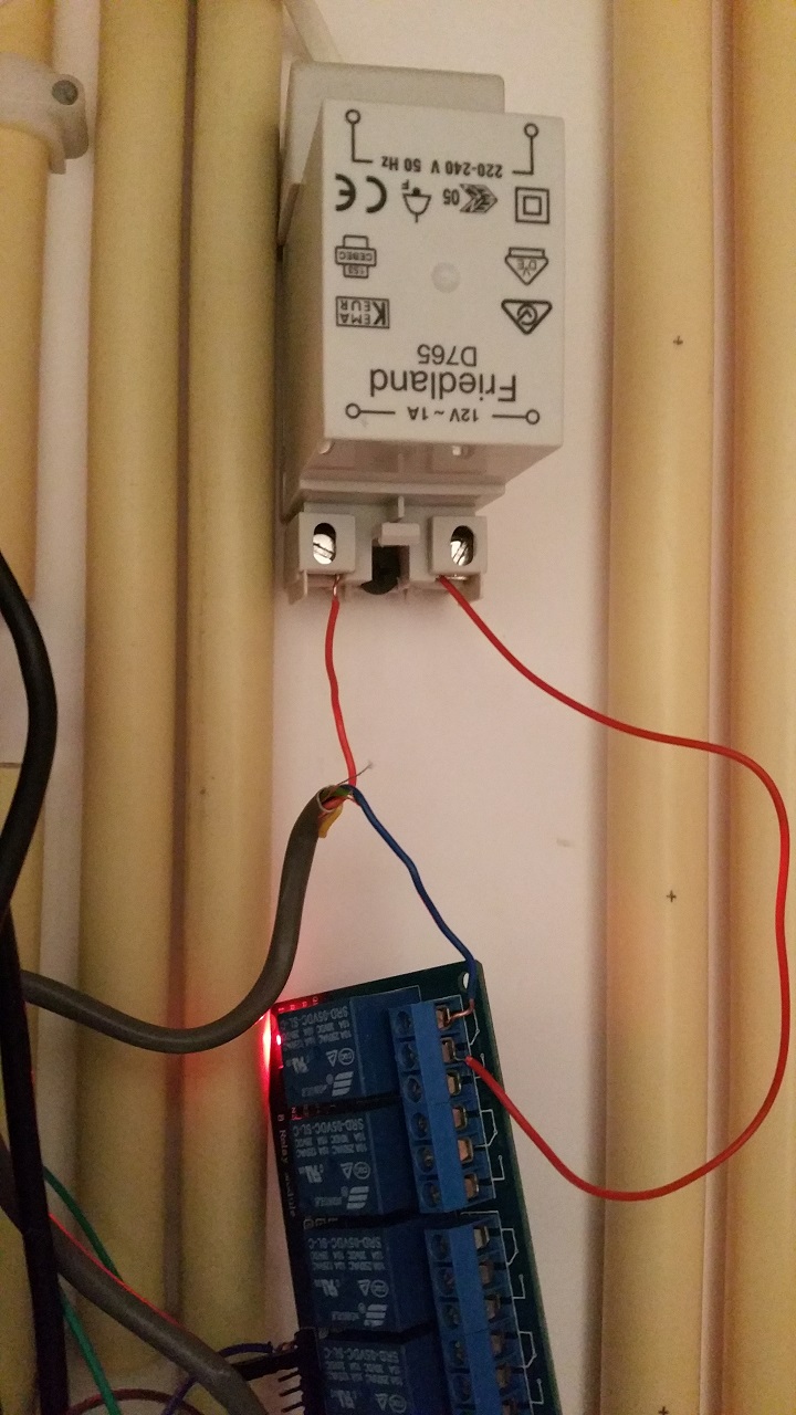
    There is no difference between blue and red, neither does it make a difference if I change the wires in what ever way. Tried all possibilities I can think of.


  • Admin

    You know that it is AC current coming out of that power supply right?


  • Yeah i know. Does it matter? It's seperated by the relay from the rest right?
    Or am I saying something stupid here.... 😕


  • Admin

    @arjen Can you post pictures of the rest of the wiring? It's still strange that you have to have it connected to normally closed. That is most likely why your doorbell is ringing when it's first powered on.


  • Sure, no prob.
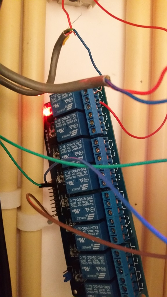
    relay.jpg
    This is the relay, at the moment a 6 port, didn't had a one port available.
    The green wire is connected to IN1 on the relay and pin4 on the arduino.
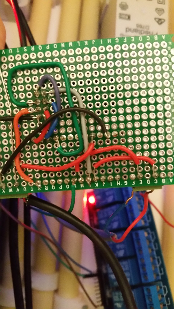
    back_print.jpg
    the backside of the print. The bottom row 'S' is pin 9 on the arduino, 'M' and 'K' is pin3 and Ground to doorbellbutton.
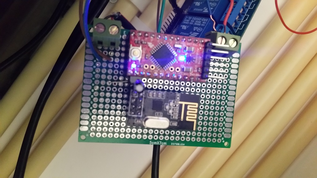
    front_print.jpg
    front side. The brown and blue on the left are 5V to the relay, on the right red and blue are input doorbellbutton.


  • Hero Member

    Did you try my suggestion?

    @korttoma said:

    For the NC problem change:

    #define RELAY_ON 1
    #define RELAY_OFF 0
    

    to:

    #define RELAY_ON 0
    #define RELAY_OFF 1
    

  • Admin

    Yeah, try @korttoma's suggestion. If that doesn't work, can you post a pic of the relay connections (all)?


  • Huh, I have the same problem as @arjen is describing too, the only difference is i'm using a 2x raly vs. his 4. I don't have an issue with the relay being on, since my node is always powered on, the pull always goes high. Might just change it in the code/wiring though when I get the Arduino IDE working again.

    Quick question: do you have the relay board powered by the Arduino, or another 5V source?


  • Made the changes to the sketch as suggested, and now I can connect it to NO.
    Just to make sure I didn't made a mistake while soldering, used a fresh nano and made all connections again. In the sketch the changes still need to be made, however as far as i could test this morning all is working fine now!
    Thanks for all the tips!

    The relay is powered by the same powersource as the arduino (6 port powered usb hub 2A).


  • Admin

    @drock1985 the relay should be powered by the same 5v power source as the Arduino but not from the arduino. It can draw too much power and cause issues when connected to the arduino.

    @arjen Great! I just noticed the selection pin (can't think of the correct name right now) on your relay. I wonder if switching that would allow you to use the original code as well as the NO connections?


  • Excellent project, great work.. So I need to pick your mind.... I have a doorbell that can change music and volume. I hope to be able to fully control it by zwave using this app with Vera...Any ideas.....


  • Admin

    @Newzwaver Hmm. I doubt this would work for you to fully control it but you may still be able to trigger it. How do you control it now? Through an app or something?


  • Hero Member

    Hello all - sorry I have been away for so long...
    This bring back memories http://forum.mysensors.org/topic/1620/mysensored-doorbell
    I wish I found a way of triggering the notification from the ring and not the other way around, as this way when something happen to your arduino the doorbell will not ring. Didn't happen yet - it works perfectly for 6 months but I would feel more relaxed if it was the other way around. Oh well...


  • Admin

    @Moshe-Livne Cool! You can look at it the other way around on the Arduino processing the ring issue you raised. I now have the ability to turn off the ring if I want to. So I guess there is some give and take 🙂


  • Hero Member

    @petewill ummmm you could still cut the ring even if it was the other way around with a relay. Sorry to be a pain 🙂 can't fight my mold hehehe. generally I find the reliability of dorrbells (especially the old wired kind) to be excellent. mine has been working flawlessly for at least 35 years.


  • Admin

    @Moshe-Livne Ok, I must have misunderstood. I thought you wanted the bell to ring no matter what then just detect the signal so you could send it to your gateway. Either way, that's why MySensors is so great, you can do pretty much what ever YOU want, not what someone else wants 🙂


  • Hero Member

    @petewill My original plan was to unintrusively detect the ring and trigger the arduino without effecting the bell circuit. However, it proved to be a bit more complicated and 2 dead arduinos and several other fried components later I gave up.


  • I am new to home automation but curious if this same setup would work by having the arduino centrally located with the transformer in a closet and use the extra connections on the existing 4 conductor wire from the transformer to connect the new relay installed in the chime?

    All this saves is some extra space and having to run 5V to the chime but one could use a larger arduino for additional automation projects rather than dedicated to just the chime.

    Very nice tutorial- very easy to follow. Thanks


  • Hey @mike0913 ,

    You can check out what I did with my Doorbell hack here (http://forum.mysensors.org/topic/2293/how-to-2-door-chime-automation-hack-thanks-petewill), it may help with your situation. Basically, I used the 16VAC input from the doorbell to power my Arduino, relays, and actual doorbell chime itself. Due to confined space, I had to mount mine in an external box below the existing door chime.


  • @petewill, thanks for the reply and sorry it took me so long. I have decided to keep it to a small project starting with the remote on off, then moving to a trigger to my camera. I plan on breaking the doorbell down once the wife is out of the house for a day, lol. Thanks again.


  • @petewill

    Thanks for the code! For some reason it is not functioning on my arduino pro, the relay doesnt do anything when I push the button on pin 3, I do see within the Vera that the button is being pushed I have no clue what is going wrong..

    This is the output from the serial monitor:
    send: 16-16-0-0 s=255,c=3,t=15,pt=2,l=2,sg=0,st=ok:0
    send: 16-16-0-0 s=255,c=0,t=17,pt=0,l=5,sg=0,st=ok:1.5.3
    send: 16-16-0-0 s=255,c=3,t=6,pt=1,l=1,sg=0,st=ok:0
    sensor started, id=16, parent=0, distance=1
    send: 16-16-0-0 s=255,c=3,t=11,pt=0,l=16,sg=0,st=ok:Doorbell Monitor
    send: 16-16-0-0 s=255,c=3,t=12,pt=0,l=3,sg=0,st=ok:1.0
    send: 16-16-0-0 s=1,c=0,t=3,pt=0,l=0,sg=0,st=ok:
    send: 16-16-0-0 s=0,c=0,t=1,pt=0,l=0,sg=0,st=ok:
    Pushing button
    send: 16-16-0-0 s=0,c=1,t=16,pt=1,l=1,sg=0,st=ok:1
    send: 16-16-0-0 s=0,c=1,t=16,pt=1,l=1,sg=0,st=ok:0
    Pushing button
    send: 16-16-0-0 s=0,c=1,t=16,pt=1,l=1,sg=0,st=ok:1
    send: 16-16-0-0 s=0,c=1,t=16,pt=1,l=1,sg=0,st=ok:0

    Anybody that can help me out?

    Thanks!

    Kind regards,

    Richard


  • @riochicken

    Never mind, I didnt know I had to enable both switches within the arduino interface... ahum..

    Thanks anyhoe!

    Kind regards

    Richard


  • Excellent hack, works like a charm! I added two extra activations for my doorbell so it rings two times short and one longer time... Is there a way to create a variable in the Vera options so you can change the number of time the relay activates? Now I added them in the code but that is not really handy when the thing is build in and such... 🙂

    Thanks!


  • Admin

    @riochicken said:

    Is there a way to create a variable in the Vera options so you can change the number of time the relay activates?

    Yeah, that should be possible. Have a look at the Irrigation Controller code. That has some examples of getting variables from the controller.


  • I had my doorbell working fine on Vera for months, but now I'm switching over to Domoticz. I used the updated domoticz version of the code above (by drock1985) but it's still not working right. My only changes were the pin assignments to match my wiring and setting the repeater to true since it's powered.

    My domoticz is version v3.4834. Mysensors ethernet gateway is working fine. When I powered up the doorbell, I got an unknown node with sketch "unknown" show up under mysensors. It has 2 children - a repeater with childID 255, and an unknown with childID 0 and a V_Tripped value.

    Any idea what I need to do to make it work?


  • @timropp

    Try this code and see if it works.

    /*
     * The MySensors Arduino library handles the wireless radio link and protocol
     * between your home built sensors/actuators and HA controller of choice.
     * The sensors forms a self healing radio network with optional repeaters. Each
     * repeater and gateway builds a routing tables in EEPROM which keeps track of the
     * network topology allowing messages to be routed to nodes.
     *
     * Created by Henrik Ekblad <henrik.ekblad@mysensors.org>
     * Copyright (C) 2013-2015 Sensnology AB
     * Full contributor list: https://github.com/mysensors/Arduino/graphs/contributors
     *
     * Documentation: http://www.mysensors.org
     * Support Forum: http://forum.mysensors.org
     *
     * This program is free software; you can redistribute it and/or
     * modify it under the terms of the GNU General Public License
     * version 2 as published by the Free Software Foundation.
     *
     *******************************
     *
     * REVISION HISTORY
     * Version 2.1 - Derrick Rockwell (Drock1985) 
     * - Complete Re-write of code to provide better flow/structure. 
     * Version 2.0 - ResentedPoet
     * 
     * Based on original concept/code by @petewill for 1 Door bell chime. See original thread
     * http://forum.mysensors.org/topic/2064/how-to-doorbell-automation-hack
     * This sketch is used to control a front and back doorbell ring with relays as well as send an
     * alert when the buttons are pressed. For front door, Connect the button to ground and digital
     * pin 3.  The relay controlling the doorbell is conntected to pin 4. For rear door bell
     * connect second button to ground and digital pin 5. The relay controlling that pin goes 
     * to pin 6.
     */
    #include <MySensor.h>
    #include <SPI.h>
    #include <Bounce2.h>
    
    #define NODE_ID 2                   // or set to AUTO if you want gw to assign a NODE_ID for you.
    #define FRONT_DOOR_BUTTON  3        // Arduino Digital I/O pin number for the front doorbell button 
    #define FRONT_CHIME_RELAY  4        // Aduino Digital I/O pin number for the front door chime relay
    #define CHILD_ID_0 0                // Child ID for the front doorbell sensor
    #define BACK_DOOR_BUTTON 5          // Arduino Digital I/O pin number for the back doorbell button
    #define BACK_CHIME_RELAY 6          // Aduino Digital I/O pin number for the back door chime relay
    #define CHILD_ID_1 1                // Child ID for the back doorbell sensor
    #define CHILD_ID_2 2                // Child ID for the mute option
    #define CHIME_MUTE_STATE            // Used to hold value of door chime mute funtion. 
    #define CHIME_OFF 0                 // Variable to define ring the chime
    #define CHIME_ON 1
    #define FRONT_CHIME_RELAY_ON LOW    // Variable for front chime. Reverse low/high if relay pin set different
    #define FRONT_CHIME_RELAY_OFF HIGH  // Variable for front chime. Reverse low/high if relay pin set different
    #define BACK_CHIME_RELAY_ON LOW     // Variable for front chime. Reverse low/high if relay pin set different
    #define BACK_CHIME_RELAY_OFF HIGH   // Variable for front chime. Reverse low/high if relay pin set different
    
    Bounce debouncerF = Bounce();
    Bounce debouncerB = Bounce();
    
    boolean CHIME_MUTE = 1;
    
    MySensor gw;
    MyMessage msg(CHILD_ID_2, CHIME_MUTE);
    
    MyMessage frontDoorbell(CHILD_ID_0, V_TRIPPED);
    MyMessage backDoorbell(CHILD_ID_1, V_TRIPPED);
    MyMessage chimeMute(CHILD_ID_2, V_STATUS);
    int pestTimeout = 4000;               // Delay between registered button presses. Stops button mashers ;) Set to whatever delay you want.
    unsigned long previousMillis=0;       // Tracks time since last door chime button press
    
    void setup() {
    
      gw.begin(incomingMessage, NODE_ID);
    
      // Send the sketch version information to the gateway and Controller
      gw.sendSketchInfo("2 Door bell/chime Monitor", "2.1");
    
      // Setup the button and activate internal pull-up
      pinMode(FRONT_DOOR_BUTTON, INPUT);
      pinMode(BACK_DOOR_BUTTON, INPUT);
      digitalWrite(FRONT_DOOR_BUTTON, HIGH);
      digitalWrite(BACK_DOOR_BUTTON, HIGH);
      
      // After setting up the button, setup debouncer
      debouncerF.attach(FRONT_DOOR_BUTTON);
      debouncerB.attach(BACK_DOOR_BUTTON);
      debouncerF.interval(5);
      debouncerB.interval(5);
    
      // Register all sensors to gw (they will be created as child devices)
      gw.present(CHILD_ID_0, S_MOTION);
      gw.present(CHILD_ID_1, S_MOTION);
      gw.present(CHILD_ID_2, S_LIGHT);
      gw.send(msg.set(CHILD_ID_2, CHIME_MUTE));
      
    
      // Make sure relays are off when starting up
      digitalWrite(FRONT_CHIME_RELAY, FRONT_CHIME_RELAY_OFF);
      digitalWrite(BACK_CHIME_RELAY, BACK_CHIME_RELAY_OFF);
      // Then set relay pins in output mode
      pinMode(FRONT_CHIME_RELAY, OUTPUT);
      pinMode(BACK_CHIME_RELAY, OUTPUT);
    
    }
    
    void loop() {
      gw.process();
      unsigned long currentMillis = millis();
      debouncerF.update();
      debouncerB.update();
      int valueF = debouncerF.read();
      int valueB = debouncerB.read();
    //Front Doorbell
    
    if ( ((unsigned long)(currentMillis - previousMillis) >= pestTimeout) && valueF != HIGH && CHIME_MUTE == 1) {
      digitalWrite(FRONT_CHIME_RELAY, FRONT_CHIME_RELAY_ON);
      gw.send(frontDoorbell.set(1));
      gw.wait(50);
      digitalWrite(FRONT_CHIME_RELAY, FRONT_CHIME_RELAY_OFF);
      gw.send(frontDoorbell.set(0));
      previousMillis = currentMillis;
    }
    
    if ( ((unsigned long)(currentMillis - previousMillis) >= pestTimeout) && valueF != HIGH && CHIME_MUTE == 0) {
      gw.send(frontDoorbell.set(1));
      gw.wait(50);;
      gw.send(frontDoorbell.set(0));
      previousMillis = currentMillis;
    }
    //Back Doorbell
    
    if ( ((unsigned long)(currentMillis - previousMillis) >= pestTimeout) && valueB != HIGH && CHIME_MUTE == 1) {
      digitalWrite(BACK_CHIME_RELAY, BACK_CHIME_RELAY_ON);
      gw.send(backDoorbell.set(1));
      gw.wait(450);
      digitalWrite(BACK_CHIME_RELAY, BACK_CHIME_RELAY_OFF);
      gw.send(backDoorbell.set(0));
      previousMillis = currentMillis;
    }
    
    if ( ((unsigned long)(currentMillis - previousMillis) >= pestTimeout) && valueB != HIGH && CHIME_MUTE == 0) {
      gw.send(backDoorbell.set(1));
      gw.wait(50);
      gw.send(backDoorbell.set(0));
      previousMillis = currentMillis;
    }
    }
    void incomingMessage(const MyMessage &message) {
      // We only expect one type of message from controller. But we better check anyway.
      if (message.isAck()) {
         Serial.println("This is an ack from gateway");
      }
    
      if (message.type == V_STATUS) {
         // Change relay state
         CHIME_MUTE = message.getBool();
         gw.send(msg.set(CHILD_ID_2, CHIME_MUTE?CHIME_ON:CHIME_OFF));
         // Store state in eeprom
         gw.saveState(CHILD_ID_2, CHIME_MUTE);
        
         // Write some debug info
         Serial.print("Incoming change for sensor:");
         Serial.print(message.sensor);
         Serial.print(", New status: ");
         Serial.println(message.getBool());
       } 
    }


  • Thanks, I'll give that a try. I don't have any need for the dual bell functionality, but we can see if it works and if so, then comment out the back bell part to simplify things.


  • Tried that sketch (with just changing pin assignments and flipping the relay high/low settings). As soon as I powered it up, the relay started clicking every 4 seconds and it never appeared in Domoticz. I think it's because after the pin is set to input, there's " digitalWrite(FRONT_DOOR_BUTTON, HIGH);" command that's like someone holding the button down.

    Went back to the original sketch I used. I changed from an auto NODE_ID to a fixed setting in the defines and re-uploaded it. The device appeared in Domoticz correctly! I've got a "doorbell sketch 1.0" with 3 devices - repeater, the doorbell button as a S_Motion, and the doorbell on/off as a S_Lights.

    However, it still doesn't work. My wiring is shown above and it worked great under Vera. Now, I cannot get the doorbell to actually chime. Nor does the outdoor button do anything. I've verified the wiring, but shorting the A0 pin to the ground input doesn't do anything like it should. However, there's ANOTHER ground next to the A0 (under the wireless card), and if I short the A0 to that ground pin, the switch shows on in Domoticz. I can change the wiring since for some reason which ground I use is making a difference.

    No matter what, still no relay action though. I tried turning the doorbell on/off switch both ways and it made no difference. In either setting, shorting the two pins turns the switch in Domoticz on.

    I was comparing the two sketches (the one I'm using, and the dual-bell one). The single bell sketch sets the button pin with pinmode(Doorbell_pin, input_pullup) where the dual uses input without the pullup. Which should be right?


  • @timropp

    The sketch I use doesn't use internal pull ups; external only.

    As for the relay clicking, could be either the jumper on the relay, or not enough current to power it properly.

    Not sure why you are having issues with either of the scripts. What type of gateway do you use?


  • It's an ethernet gateway.

    I don't think it's really a Mysensors issue though as I think about it - the doorbell should ring when you press the button whether you have the gateway running or not. And I'm not even getting that. In fact, I AM getting the signal to the gateway, but it's not activating the relay.

    Is it possible that the doorbell on/off switch isn't working right in the code? I never used that before. I think I'll try tomorrow (kids in bed now, so can't really play around with a doorbell!) removing that switch for now and have it always set to on.

    I looked through comparing the sketch I'm using now (the one drock1985 made that's for domoticz) and the original. The only change is moving the gw.send command and changing it slightly. But again, that shouldn't impact the bell physically working. So there's something else going on.

    Is there a way to check if the code uploaded to the arduino correctly? I'm using the rboard and a FTDI to upload. I'm wondering if something isn't going weird there and it's not uploading correctly and that's why I'm getting different issues every time I try something...


  • Not really. You could try uploading at a slower speed. Slower speed over serial usually equals less chance of missed data.

    Have you tried running this connected to your PC and viewing the data from serial console/window? Copy/paste the output from the serial monitor so we can see what's going on.


  • Yep, both those are on my to do list fo tonight. Thanks for your help troubleshooting!


  • I have installed the doorbell sketch on my testboard. This just to see how it should be working. First sensor with a relay for me basically 🙂

    But I have a question. I have use the sketch, I have two devices coming up in Domiticz, a security sensor and a light switch. But basically I don't get the function of these buttons?
    I think the security sensor responds on the doorbell press?

    Also I think the other button is to activate the physical doorbell which could switch the relay? But I would expect that the security switch button in Domoticz could also activate the relay remotely, but this is not the case? Because, I don't see an option to switch the relay remotely in Domoticz?

    So it is working; but any help is appreciated if somebody could explain the functionallity for me and if this is the expected behavior 🙂


  • @rnollen

    I know when I was playing with Domoticz the Doorbell sketch would show up as a security light and a light for me. The security light I changed to a motion sensor in Domoticz (click edit on your dashboard/switches tab). After that when I pressed the doorbell button, the motion sensor would switch on to show the button was pressed, then immediately back off. Although for it to turn off automatically, I may have had to tell domoticz to do that after xx seconds, can't remember for sure now.

    And yes you are correct, the second switch is a 'mute' for the doorbell. If off, the doorbell won't sound (switch the relay).


  • Hi guys,

    I'm nearly there, but need a little help if anyone can!

    For my setup I've got a diode bridge followed immediately by a buck converter, so the doorbell's 18v AC comes down to 8v DC. My plan was to run the doorbell AND the arduino off this same supply, but I'm guessing now that it may not be possible. The reason for this was down to there only being 2 wires to the doorbell. The doorbell works fine off 8v DC and so does the arduino. The issue however is when i both power the arduino and the doorbell at the same time of the same supply. The relay opens and then the arduino resets. No chime.

    What should I do? Wiring layout is exactly the same as above but the 8v DC loops through the relay to the doorbell as well as going to VIN/GND on the Arduino Nano.

    I can't have the arduino at the power supply end as I need the doorbell button connections, so I'm hoping someone might have some ideas around splitting out the power supplies at the doorbell end? Or smoothing it or something like that.

    Power is red/yellow from the wall. Doorbell button is yellow/yellow from the wall. brown/brown is soldered/heat shrunk to red/red within the housing. NRF is on headers, so it's lifted out in this photo.

    0_1472919335198_IMG_20160903_145835.jpg

    Thanks,

    Patrick


  • Or can i just get away with a better power supply for the both? Essentially I've got a pulse-detecting mysensors node, a doorbell node and a doorbell itself running off a cheap-ass ebay chinese full-bridge rectifier and step-down converter (120v AC > 8v DC). The doorbell takes 8v DC so I'm using that as the common voltage.


  • @pjblink - what are the components you have built in there? I see the Arduino Nano and a relay - are they all attached to a board? Is there a radio in there, too? I clicked on the (old) link above for Mini RBoard, but I get a gateway error when going to the page to purchase...


  • Hi crodgers,

    So yeh, there's a nano on headers, relay, nrf on headers and 3 wire terminals - 1 for the doorbell button, 1 for the bell itself and another for the DC IN. Everything is soldered to a prototyping board which has now been trimmed down to fit in the doorbell housing.

    Thanks,

    Patrick

    0_1472974471673_IMG_20160903_131746~2.jpg


  • Working without the doorbell load attached:
    mysensors enabled doorbell working without load

    Failing when I attach the load:
    mysensors enabled doorbell failing with load


  • I've just tried it with both 1000uF and then a 4700uF cap across VIN/GND on the arduino with only slightly better results. It'll ring, but the relay stays open most of the time and the arduino needs resetting to release it 😞


  • Hardware Contributor

    @pjblink - late into the discussion, but have you tried changing to another power supply or another regulator? It might that its to unstable for your node... atleast temporary to rule things out.


  • @sundberg84 That was definitely on the cards...but it looks like I might have got it working. I did 4 things in one go, which is unlike me, so now I have to break things down to see which one helped (if it wasn't all)...1st thing was a 4700uF cap over the arduino VIN/GND, 2nd was a 1000uF cap over the relay +- 5v,… 3rd was to reflow a few of the GND solders and finally I dropped the voltage regulator from 8v to just under 7v...and hey presto...

    mysensors doorbell node working – 00:22
    — Patrick Blinkhorne


  • Hardware Contributor

    @pjblink - a bad ground connection has been a pain for me alot of times... good you got it working.


  • So it kept failing after 2 or 3 rings...frustrating! I enabled all the debug and noticed it kept failing just before sending out the "off" message. It didn't reset, just stalled. This was the case even when powered by USB. And then I remembered how sensitive the NRFs are to fluctuations in power and I hadn't got round to putting a cap on there yet!!! I put a spare 1000uF (47uF are on order) and so far it hasnt caused me any further issues! So now I've got 3 huge capacitors on there, and it looks ok...touch wood.


  • It still looks to be having issues 😞 looks like the arduino will hang just before sending the command to untrip.


  • Great how-to for a beginner. But now I'm stuck because of my lack of knowledge to rebuild the sketch for MySensors 2.0. Does anyone already rebuild it and willing to share?


  • How are you powering the relay? Are you trying to run it directly from an arduino data line? If so, that could be your problem. I am currently working on a motion sensor light with a PIR, LDR, and a relay. Now the relay I am using is a 12 volt relay, but the concept would be the same for a 5 volt relay. The idea is to use a transistor to trigger the relay from a separate power source. I used an 2N3904 NPN transistor to switch the the negative side of the power to the relay. You simply connect the emitter to your ground, the collector to the negative side of your relay and the base goes to your arduino data pin. You may need to add a pull-down resistor on the transistor base to ground depending on your situation. In my case it worked fine without it. Also, you should still of course put your flyback diode across your relay coil to prevent voltage spikes.

    The above assumes that you are using a relay on it's own and not a relay module like the ones you find on ebay. The relay modules already have the transistor and diode already built in, and some even use an optocoupler for added isolation.


  • My test situation is Nano+Radio with double relay module and push button for the bell. Relay is powered by the 5V by Arduino, and i have tested this with the example sketch (+modification for double relay) and everything was working fine. The issue i am having is the original sketch (1 bell + 1 relay) is made for mysensors 1.x, and i am running 2.x and have no idea how te rewrite this.


  • @Samster here's the link to converting code to 2.0:
    https://forum.mysensors.org/topic/4276/converting-a-sketch-from-1-5-x-to-2-0-x

    I followed this recently (different sketch) and it works just fine as long as you take your time and make sure you do each step properly. Post back on how you get on, if you're still stuck I might be able to give a hand next week but I'm pretty new at this myself.


  • @mrwomble Thank you, that's very helpfull, i will start puzzling around and share the result.


  • Ok, finally worked this again today. Here's the status. I modified the sketch to update it to 2.0, giving me this:

    /*
     * The MySensors Arduino library handles the wireless radio link and protocol
     * between your home built sensors/actuators and HA controller of choice.
     * The sensors forms a self healing radio network with optional repeaters. Each
     * repeater and gateway builds a routing tables in EEPROM which keeps track of the
     * network topology allowing messages to be routed to nodes.
     *
     * Created by Henrik Ekblad <henrik.ekblad@mysensors.org>
     * Copyright (C) 2013-2015 Sensnology AB
     * Full contributor list: https://github.com/mysensors/Arduino/graphs/contributors
     *
     * Documentation: http://www.mysensors.org
     * Support Forum: http://forum.mysensors.org
     *
     * This program is free software; you can redistribute it and/or
     * modify it under the terms of the GNU General Public License
     * version 2 as published by the Free Software Foundation.
     *
     *******************************
     *
     * REVISION HISTORY
     * Version 1.0 - PeteWill
     * Version 2.0 - timropp, updating for MySensors 2.0
     *
     * DESCRIPTION
     * This sketch is used to control a doorbell ring with a relay as well as send an
     * alert when the buttons is pressed.  Connect the button to ground and digital
     * pin 3.  The relay controlling the doorbell is conntected to pin 4.
     * 
     * Watch the How To video here: https://youtu.be/nMIcalwpstc
     */
    
    #define MY_RADIO_NRF24
    #define MY_REPEATER_FEATURE
    
    #include <MySensors.h>
    #include <SPI.h>
    #include <Bounce2.h>
    
    #define NODE_ID AUTO // or set to AUTO if you want gw to assign a NODE_ID for you.
    
    #define DOORBELL_PIN A0      // Arduino Digital I/O pin number for the doorbell button 
    #define RELAY_PIN  4         // Arduino Digital I/O pin number for the relay 
    #define DOORBELL_CHILD_ID 0  //ID of the doorbell
    #define SWITCH_CHILD_ID 1    // Id of the switch that will control doorbell sound
    #define RELAY_ON 1
    #define RELAY_OFF 0
    
    Bounce debouncer = Bounce();
    
    MyMessage switchMsg(SWITCH_CHILD_ID, V_LIGHT);
    MyMessage doorbellMsg(DOORBELL_CHILD_ID, V_TRIPPED);
    
    unsigned int doorbellDelay = 1000; // interval at which to keep the doorbell button sensor triggered (milliseconds). This is used to stop people (kids) from pressing it too often
    unsigned int ringTime = 400; //How long the doorbell relay is on (in milliseconds)
    unsigned long doorbellMillis;  //Used to keep track of the last doorbell button press
    unsigned long doorbellTimer;  //Used to keep track of doorbell ring time
    byte doorbellPreviousVal;  //Used to keep track of doorbell button pressed state
    boolean ringDoorbell;  //Used to initiate the ring doorbell if statement
    boolean doorbellSound; //Used to keep track if the doorbell should sound or be silent.  Value recieved from doorbell on/off switch
    boolean doorbellOff = true;  //Used to keep track of doorbell ring state
    
    void setup()
    {
      // Setup the button and activate internal pull-up
      pinMode(DOORBELL_PIN, INPUT_PULLUP);
    
      // After setting up the button, setup debouncer
      debouncer.attach(DOORBELL_PIN);
      debouncer.interval(5);
    
      // Make sure relays are off when starting up
      digitalWrite(RELAY_PIN, RELAY_OFF);
      // Then set relay pins in output mode
      pinMode(RELAY_PIN, OUTPUT);
    
      // Set doorbellSound to last known state (using eeprom storage)
      doorbellSound = loadState(SWITCH_CHILD_ID);
    }
    
    void loop()
    {
        unsigned long currentMillis = millis();
      //Check to see if doorbell button was pushed.
      if (currentMillis - doorbellMillis > doorbellDelay) //used to stop doorbell from being pressed too frequently
      {
        debouncer.update();
        // Read doorbell button value
        byte doorbellDetect = !debouncer.read();//read, then reverse the value so it will send correct trigger state to controller
    
        if (doorbellDetect != doorbellPreviousVal)
        {
          //Serial.print("doorbellDetect Value: ");
          //Serial.println(doorbellDetect);
          send(doorbellMsg.set(doorbellDetect)); 
          if (doorbellDetect == 1)
          {
            ringDoorbell = true;
            doorbellTimer = currentMillis;
          }
          doorbellMillis = currentMillis;
          doorbellPreviousVal = doorbellDetect;
        }
      }
    
      if (ringDoorbell)
      {
        if (doorbellSound)
        {
          if (doorbellOff)
          {
            digitalWrite(RELAY_PIN, RELAY_ON);
            //Serial.println("Doorbell sounded.");
            doorbellOff = false;
          }
          else
          {
            if (currentMillis - doorbellTimer > ringTime)
            {
              ringDoorbell = false;
              digitalWrite(RELAY_PIN, RELAY_OFF);
              //Serial.println("Doorbell off.");
              doorbellOff = true;
            }
          }
        }
      }
    }
    
      void receive(const MyMessage &message) {
        // We only expect one type of message from controller. But we better check anyway.
        if (message.isAck()) {
          Serial.println("This is an ack from gateway");
        }
    
        if (message.type == V_LIGHT) {
          // Change relay state
          doorbellSound = message.getBool();
          // Store state in eeprom
          saveState(SWITCH_CHILD_ID, doorbellSound);
    
          // Write some debug info
          Serial.print("Incoming change for sensor:");
          Serial.print(message.sensor);
          Serial.print(", New status: ");
          Serial.println(message.getBool());
        }
      }
    
    void presentation()
      {
      // Send the sketch version information to the gateway and Controller
      sendSketchInfo("Doorbell Monitor", "1.0");
        // Register all sensors to gw (they will be created as child devices)
      present(SWITCH_CHILD_ID, S_LIGHT);
      present(DOORBELL_CHILD_ID, S_MOTION);
      }
    

    Sitting on my desk, it works fine. It appears in Home Assistant, clicks the relay when A0 is shorted to ground, and that appears in HASS as a motion event. Seems good, so I installed it in the doorbell. Doesn't work there. I get one ring when I hook up power, and then nothing. I checked again the leads from the physical doorbell button with a multimeter - I get a good continuity buzz when I press the button and silence when not pressed. Then I discovered something - if I physically unhook the wire going to A0 and reconnect it, the doorbell rings and I get that notification in Hass. If I unhook and reconnect the wire again, same thing. So that makes it appear that the A0 is being constantly grounded - is that possible? It acts like my physical doorbell button is stuck in the pressed position, but the multimeter indicates it's fine.

    Further testing - If I connect the board to the doorbell system but leave the physical doorbell button disconnected, then attach a spare piece of wire to A0 and ground it, the system works perfectly. So it's definitely something related to the physical button.

    On thing I've realized - I THINK the outdoor button is an illuminated one, which isn't illuminated with this system. Could that light be the cause? If so, why doesn't the continuity test show it as continuous? I think I'll go buy a basic non-illuminated button and install it and see if that works. Or just pull the button out of the wall, disconnect the wires, and then short them together. Duh, that'd be easier and cheaper. I'll try that this afternoon - have a wedding to get to first.


  • @timropp said:

    I THINK the outdoor button is an illuminated one, which isn't illuminated with this system. Could that light be the cause?

    The button is probably illuminated with LEDs and a resistor (depending how old it is). This could complete the circuit to the digital input on the arduino making it look like the button is pressed. It is probably not seen on a continuity test when the button is not pressed because the resistance is enough where you don't have full continuity. See if reversing the wires into the arduino A0 and ground gets it working. If the doorbell is illuminated with an LED and a resistor that should reverse the current flow of the LED/resistor into A0 on the arduino in effect preventing that problem.


  • It's definitely the illuminated button. I pulled it out and connecting the wires rings the bell correctly. I hadn't thought about swapping the wires... It is pretty new but I wasn't considering the possibility of it being led. I'll give that a try. Worst case, replace it with a non lit button. Just glad to have finally figured it out!

    edit: actually, I'm betting it's not a LED. These buttons are typically on a 16VAC system, so a LED wouldn't work without more components. Whereas a simple incandescent bulb works fine on AC. So I think I probably just need a new button.


  • @timropp said:

    actually, I'm betting it's not a LED. These buttons are typically on a 16VAC system, so a LED wouldn't work without more components. Whereas a simple incandescent bulb works fine on AC. So I think I probably just need a new button.

    Actually an LED WILL work on AC. It will just flicker at 50/60 Hz (Depending on what country you are from) when connected with only a resistor which is only slightly noticeable to the naked eye. The flickering is because it is only lighting the LED on one half of the AC sine wave. An LED is a current controlled device, so all you need to make it work on AC is the correct size resistor to limit the current for whatever voltage you put on it. You can put more complex components in to stop the flickering such as a bridge rectifier, but for very basic operation it is not needed.


  • Final update - no local stores carry a non-illuminated doorbell button. Argh. So I ended up taking the button apart on mine, yanking the incandescent bulb out, and putting it back together. Since it's held together with just some bent over tabs, they broke off and I had to glue it back together. Once I did, everything worked perfectly. The sketch I posted above is working great - doorbell rings and the ring appears in my Home Assistant like it should.


  • Admin

    @timropp Glad you got it working!


  • Thanks, guys! You can't even imagine how much time I spent to find the solution. Currently works perfectly! Hope everything gonna be alright


Log in to reply
 

Suggested Topics

  • 8
  • 1
  • 1
  • 7
  • 5
  • 2

38
Online

11.5k
Users

11.1k
Topics

112.7k
Posts