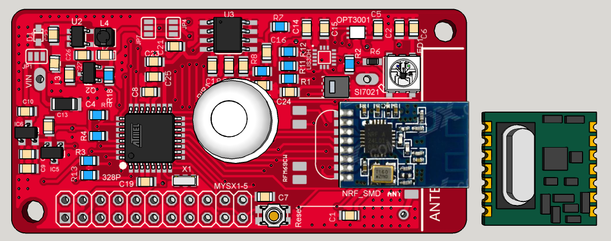
My MYSX Multisensors board
-
impressive! One thing, have you added pullups on CE lines for the radios and external flash? If not, then I would advise you to add it.
During the validation of the sensebender micro, @blacey had trouble programming the 328p with his ISP dongle. Adding pullup on radio / flash CE lines solved his problem (that's also why we have it on the sensebender now :)
Perhaps you should consider to remove any copper near the antenna area (I can see that you have the antenna connector for the RFM module just besides the antenna point on the NRF module.. Could that be moved out of the way, and leave the area without any copper?). Also seems that there is a dotted line in the copper layer surrounding the antenna area.
-
@HenryWhite : lol :smiley: cool. I hope you will enjoy. just for curiosity, which design are you tempted to build?
@tbowmo : that is exactly why I posted some preview, to get feedbacks like that. thx :)
So good to know.
Yes there are pullups for radio and eeprom. we can see on top view, the first row bottom right corner.
The dotted cutoff plane, I need to check you are right, ugly, I need to lower width.
For ground plane near nrf antenna, totally right, I am thinking 1) rearrange a little near the ws2812, but better like you said 2) shift antenna pad. I will look at this.
Other thing I will try tonight, is making passives 0805 and keep 0603 for booster part. But I am not sure for 0805 if there will be enough room. I say this because I prefer to handle 0805, but I want enough space between passives this time. -
Your project is not yet on openhardware.io !! What are you doing ?? ;)
Très belle carte en tout cas ! J'ai hate de voir comment ça fonctionne.
-
@carlierd: merci :)
Last night, I made some change from previous feedback ;)
- 2 versions :
- my preferred stepup version (not friendly because of the tiny stepup like I said)
- a buck version. But an interesting one, and of course it is better to use with lithium than classic lipo&co (sefldischarge...)... But in case, some people would be disappointed by inaccessibility of the stepup rev, I have done this new one. For 3 or 4 primary AA/AAA cells, or other setup... Before, when I was seeing lot of cells in a device, I was thinking "what a battery eater!!". But now I am thinking different, it can be justified in case the device is low power ;) So it is an alternative, why not.
- 0805 passives on two version (but for the stepup passives, I keep 0603 around it, shorter routes)
So which buck I choosed?? I could have choosed some dfn from TI or Linear...there are some great. But dfn is not easy for everyone ! So I found, a not yet released (new) ic, and I am waiting samples from a local distributor.
It's XC9265:
- lot of variant
- 2 to 6V vin
- the 2.9V Vout samples I am waiting for is rated 0.7uA in active mode.
- 90% efficiecny at 10-15uA light load
- and not the least, SOT25 package.
Wow, another crazy nugget! Hum..I think manufacturers should reward me, am I good at advertising ??? ahaha :laughing: And for the fun, preview of the buck rev with 0805 passives.
does it look better now @tbowmo ? your feedbacks are always appreciated :)And free of charge :laughing: Sorry...it just makes me laugh :)
Here an eval board I have designed for this buck.
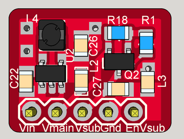
As you can see on it, there still are :- 2x ferrite on Vout and Gnd
- as this buck is only one Vout. I added one mosfet to have a second enable/disable Vout2 . So we have Vmain always active(0.8u Iq), and a switchable Vsub.
Size of this eval board : 12x16mm
-
@tbowmo: thx. So I am happy.
I will post schematic soon, need to clean my notes! it's rather simple.@shabba: thx. I am thinking about it...I don't know for the moment the easier/cheaper way for me and you. China or homemade batch..and there is a fablab near my home, which is able to handle mini batch...
And it is chinese new year so I can't get a quote. I need to do the BOM now to evaluate. But I have tried to keep things cheap vs perf vs quality..It's 2layer (so cheaper, maybe for emi it would be better 4layer, but I will see), radio should not be included in price (we can choose which one so), atmel or passives are cheap, not too much ic. I am much more worried about sensors soldering china price...But I will see, it's planned. -
Really great project. Thanks for giving me ideas and inspiration. This was my next step to go for after my thermostat and dimmer project
-
For the box
Is the battery kept away from the antenna part of the design. My question is is the board longer than an AA battery including battery "connectors" -
If you have space issues i think you should go for 0402 size, its not that hard to solder if you have a magnifing lamp, a good soldering iron, a tweezers and some thin soldering iron :)
-
Yep I have already all these tools ;)
I have already soldered 0402, for sensebender for instance :) I ordered 3 boards at oshpark, couldn't wait! It works well.
But when I can, I prefer 0805, or 0603 min. My way to share. 0402, not everyone will try, nor 805 I know..! And I prefer to minimize mistake source , less small things, less error possibilities at prototyping. I could have choosed atmel vqfn too!
I like when I see someone sharing 0603/0805 files. When I see something 0402 and really need it, I make it 0805/0603 ;)
For this board I think 0603 min is ok. For the moment it's 0805, I will try to add a little bit more clearance before ordering it.
It could be a little bit smaller with 0402, but not much, there are antenna area, and battery connector, components on top... And between a 6 or 6.5cm pcb...hum is it really useful, I am far away of coincell size so! And I don't want to put radio on bottom, between the pcb and battery holder. it would add more thickness.Sensebender is a very special case, a challenge. It is the ultra mini sensor board. but no batt holder. Add it and a box, it's not the same size. There are minimal
Hello! It looks like you're interested in this conversation, but you don't have an account yet.
Getting fed up of having to scroll through the same posts each visit? When you register for an account, you'll always come back to exactly where you were before, and choose to be notified of new replies (either via email, or push notification). You'll also be able to save bookmarks and upvote posts to show your appreciation to other community members.
With your input, this post could be even better 💗
Register Login