My MYSX Multisensors board
-
Hey :)
I am enthousiast to show you my very new project : my low power multisensor for light loads.
My roadtrip in the lowpower jungle world.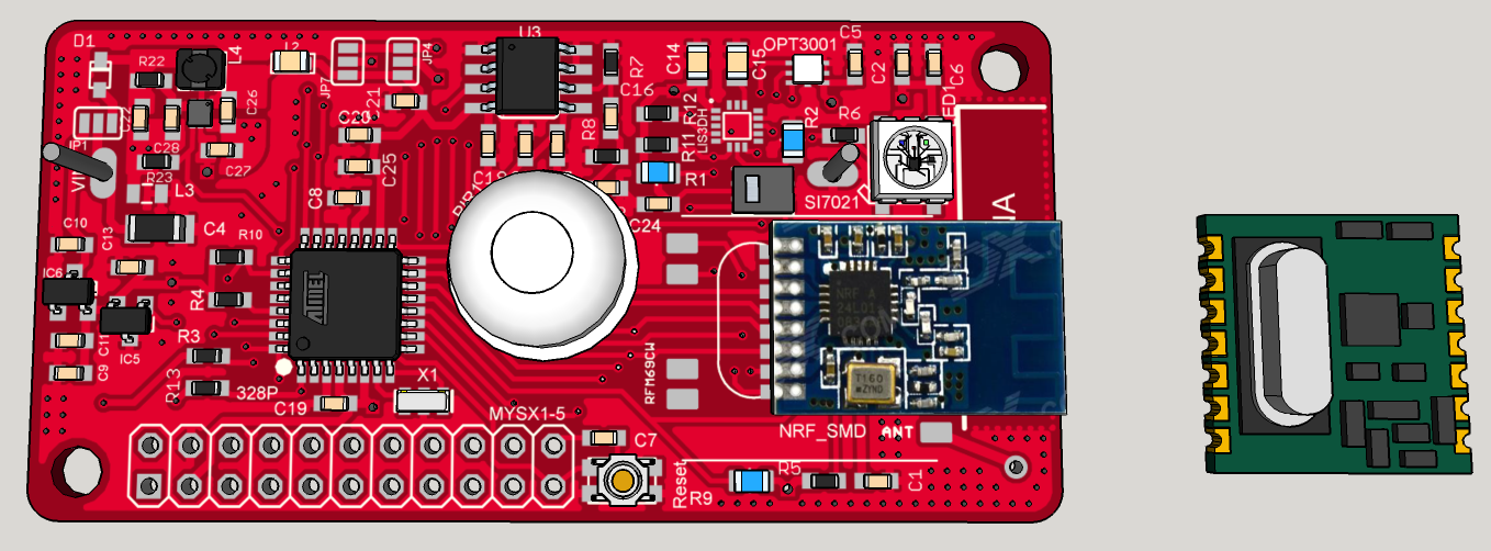
I wanted to make an update on my other "mytinycamel" post, but I would like to explain my way for this board, so...Ah, and I will make it openhardware of course ;)
Why this board as I have already Mytinycamel in the pipeline ???
I want to factorize some of my needs and costs (and that is not a question of me only, I have family, friends..which want my boards too, so why not make it the best I can). I need to have in each room, at least or optionnally, one :
1) We are here for Sensors :
- PIR motion sensor : LHI968 + e931.96 ic (integrated LDO and autocalibration for common PIR sensors)
- temperature/humidity sensor : SI7021
- ambient light sensor : OPT3001
- Accelerometer (why not for antithief) : LIS3DH
- a reed switch for the door
- a buzzer (why not, for fun, optional)
- indication led : for the moment, ws2812b
As you can see, I have choosen all these sensors for their cost/ultra low powermode. You can find better IMU but >6€ (it is for antithief, so I don't need a 9DOF!)
WS2812b, buzzer are on an enable/disable power rail, so in sleepmode I will disconnect it. Ambiant light OPT3001 is interesting too. You can set by i2c, light thresholds and trigger an interrupt on your mcu which is in deepsleep. Could be useful in some scenario.my first problem is about PIR motion sensor ic, it needs 2.6V min. And Mytinycamel concept is based on a 2Vto3V variable vcc.
Humm..That is why I have designed this board. I want something the most low power I can, and 3V constant (2.7V min). Go to switching regulators, not powering it off like with mytinycamel.
2) DC step-up switching regulator : TPS610981(x)
This one rocks, it's a "pépite". French revealed (maybe my bad english too lol), I say this when I like it and compare this to a gold nugget ;) I have digged digged in the river of the lowpower, yeah:) lol I hope your are laughing of my bullsh**, because I can't stop!
Unfortunately, this ic is not handsolderable. I will use reflow process. But I am already making a rev1.1 with a crazy SOT23 buck ;) more friendly, but a buck is not one 1.5V cell, it would need 4x to get same result ;)
Common switching reg (stepup or buck) are not very efficient at lights loads (like 10uA, during sleepmodes..). And they use few or more uA in quiescent current Iq. All uA added, will be increased due to efficiency.
My choice is : for controlled light loads, I go to stepup, and for bigger loads a buck.Shortly, its specs :
- 0.7V min voltage, so you can get every drop of one 1.5V AA/AAA ;)
- Ultra low Iq, 400nA
- 80% efficient even at 10-15uA!
- two power rails (in datasheet lot of interesting variant).
- now crazy thing, first you have bypass mode (if vin>3V for the 3V variant, vin is directly connected to vout), and then 0.7-3V vin -> 3V vout. Now if you want to disable the stepup, it goes in low powermode, which means the power rail n°2 is disconnected, but power rail n°1 still remains at 3V in ultra low Iq of 400nA, 80% efficient! So it's possible to cut off things with vout2, and have low power light load things on vout1.
that's like pizza, I want the complete. ahah, really cool, isn'it ?
now, its cons are it is not friendly to solder, and it is 2x50mA max. But we must do things smart..
3) A little word about batteries, energy harvesting..
I have thought a lot about this, read lot of interesting design notes. I think it's a lot a matter of taste but :- 3V coincell. Interesting, but not enough if I want to use RFM69 (Tx mode is a eater). It could be interesting used in a solar harvesting extender mode. But it would increase my cost, and I think I can last very long time how I will do, and for the use I need; and for the cost... And solar require some placement, which is not really the best usecase for this node.
But it is thin, so I don't forget it, it can be cool too. - 1.5V AAA not bad, thin, 1200mAh. definitely not bad compared to coincell. I like it :)
- 1.5V AA 2500mAh alkaline, 3000mAh. That IS Cool !! You have always an AA or AAA somewhere and here we go!
- 1.5V LR14 : 8000mAh. Wow! If I have place, like at ceiling edge, sure I will use it.
- lipo. definitely not interesting for this node. Too bad selfdischarge rate. can vent.
- Same thing about phone battery. not available everywhere, how long time for a model, can vent too, and self discharge is not the best. maybe 2years with no load. I don't imagine with a load..Compared to primary lithium which is 10years min theoretically...
- rechargeable lisocl2. interesting too, but not available everywhere. Expensive, need a buck, ...
As you can see, I am searching for less maintenance (less battery replacement...), cost and availability. So ok a booster is less efficient than a buck, but with a buck you can't use only one AA/AAA, héhé! A booster is not as efficient as battery powered only, but you can have constant vcc, and use the whole battery.
So it's my analysis, my personal interpretation from gurus of low power...maybe there are better option..Don't hesitate to tell me. I do not argue to be an expert ;)
My favorite config will be :
- 1AA lithium 3000mAh
- when I can, 1LR14 8000mAh
- for ultra thin and I accept worse maintenance: coincell
- try the rfm69 listenmode. one other thing why I wanted something efficient at light loads.
I suggest you to look at oregon battery lifetime calculator on google. and you will understand with one AA of 3000mA, if I have an Iq of says 30uA at 0.7 vin (a circuit Iq of says 15uA at 3V will give us 26-30uA at 0.7v vin batt end of life so the worse case). Lifetime of the system 3years mini with only one AA ;)
4) Other requirements :
-
rfm69 or nrf24 smd for the radio
-
MYSX 1.5 Connector. That was really not easy at all to fit it!!! Lot of time, I was near to give up! But, even if I don't need it, it could be very helpful for debug. So I follow you on this @Anticimex ;)
-
LDO SOT footprint in case I don't want to use the stepup reg.
-
ATSHA204A ic footprint : authentication (for PIR, reed switch...)
-
Eeprom for OTA. Same thing, eeprom needs to be in low power mode.
-
optional pullup for reedswitch...
-
battery measurement
-
smd jumper to choose if I want SPI bus Vcc on vout1 or vout2
-
smd jumper to choose if I want I2C sensors on vout1 or vout2
-
all component on top to boost production, or decrease cost if externally produced (we can dream!). I was not able! there was not enough space, so there is only eeprom on bottom. not bad!
-
Make the best I can for improve overall quality and reliability like
shielded ferrite for booster
ferrite and emi bead for booster Vout, and another one between gnd_Booster/GND
Optional capacitor near battery
optional capacitor near ferrite to improve emi filter
vias on board edge and near antenna pad to improve ground
no ground plane on one edge of the board for antenna
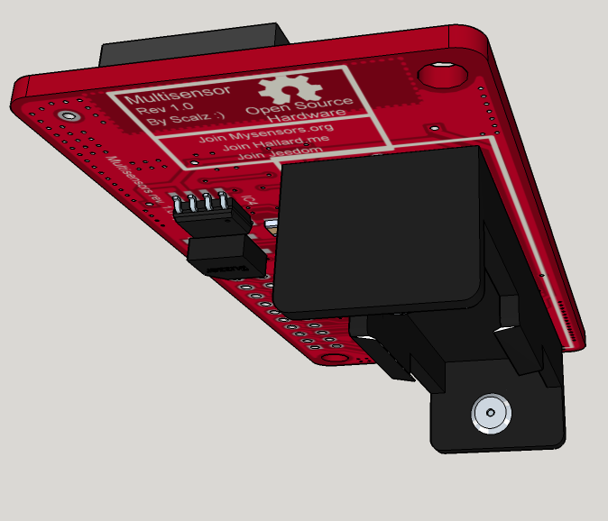
PCB : Size 65mmx32mm
Height of the box depends on coincell, or AA. For AA it's 22mm, compact.Last notes : I put this here in case you have feedbacks, or there are some infos that could help you...but It is not a noob board, sorry. Much more for reflow oven owner. How could we do to make things like this available for others??? I am thinking maybe of a simple eval board for the booster. Don't know if chinese would be interested in?
I have not ordered yet, I am making the last decisions, but my drc are ok. cool. just a matter of time, and chinese new year now... -
@hek: thx, I'm very proud you like it guys :)
My dream was to have something commercial looking, one stencil, one side, choose what you want and go to reflow. But I would like the community can benefit of it, if it works well of course! I need to think the best way, if you have ideas....
I'm a little bit disappointed that chinese new year coming, but I wish happy new year to chinese guys ;)
That will let me some time to finish some work in progress like my rollershutter node, 3d printer... -
@hek: thx, I'm very proud you like it guys :)
My dream was to have something commercial looking, one stencil, one side, choose what you want and go to reflow. But I would like the community can benefit of it, if it works well of course! I need to think the best way, if you have ideas....
I'm a little bit disappointed that chinese new year coming, but I wish happy new year to chinese guys ;)
That will let me some time to finish some work in progress like my rollershutter node, 3d printer...@scalz said:
3d printer...
OT: btw I decided to build my own 3D printer too, since you put that idea into my head and i can't wait until i can afford an ultimaker.. :smile:
-
impressive! One thing, have you added pullups on CE lines for the radios and external flash? If not, then I would advise you to add it.
During the validation of the sensebender micro, @blacey had trouble programming the 328p with his ISP dongle. Adding pullup on radio / flash CE lines solved his problem (that's also why we have it on the sensebender now :)
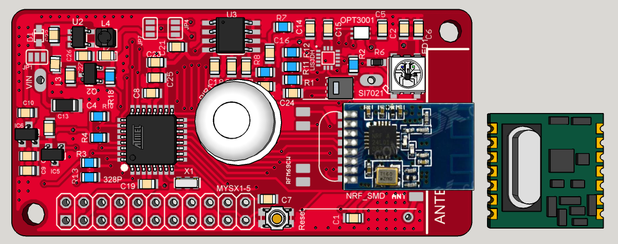
Perhaps you should consider to remove any copper near the antenna area (I can see that you have the antenna connector for the RFM module just besides the antenna point on the NRF module.. Could that be moved out of the way, and leave the area without any copper?). Also seems that there is a dotted line in the copper layer surrounding the antenna area.
-
@HenryWhite : lol :smiley: cool. I hope you will enjoy. just for curiosity, which design are you tempted to build?
@tbowmo : that is exactly why I posted some preview, to get feedbacks like that. thx :)
So good to know.
Yes there are pullups for radio and eeprom. we can see on top view, the first row bottom right corner.
The dotted cutoff plane, I need to check you are right, ugly, I need to lower width.
For ground plane near nrf antenna, totally right, I am thinking 1) rearrange a little near the ws2812, but better like you said 2) shift antenna pad. I will look at this.
Other thing I will try tonight, is making passives 0805 and keep 0603 for booster part. But I am not sure for 0805 if there will be enough room. I say this because I prefer to handle 0805, but I want enough space between passives this time. -
Your project is not yet on openhardware.io !! What are you doing ?? ;)
Très belle carte en tout cas ! J'ai hate de voir comment ça fonctionne.
-
@carlierd: merci :)
Last night, I made some change from previous feedback ;)
- 2 versions :
- my preferred stepup version (not friendly because of the tiny stepup like I said)
- a buck version. But an interesting one, and of course it is better to use with lithium than classic lipo&co (sefldischarge...)... But in case, some people would be disappointed by inaccessibility of the stepup rev, I have done this new one. For 3 or 4 primary AA/AAA cells, or other setup... Before, when I was seeing lot of cells in a device, I was thinking "what a battery eater!!". But now I am thinking different, it can be justified in case the device is low power ;) So it is an alternative, why not.
- 0805 passives on two version (but for the stepup passives, I keep 0603 around it, shorter routes)
So which buck I choosed?? I could have choosed some dfn from TI or Linear...there are some great. But dfn is not easy for everyone ! So I found, a not yet released (new) ic, and I am waiting samples from a local distributor.
It's XC9265:
- lot of variant
- 2 to 6V vin
- the 2.9V Vout samples I am waiting for is rated 0.7uA in active mode.
- 90% efficiecny at 10-15uA light load
- and not the least, SOT25 package.
Wow, another crazy nugget! Hum..I think manufacturers should reward me, am I good at advertising ??? ahaha :laughing: And for the fun, preview of the buck rev with 0805 passives.
does it look better now @tbowmo ? your feedbacks are always appreciated :)And free of charge :laughing: Sorry...it just makes me laugh :)
Here an eval board I have designed for this buck.
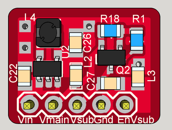
As you can see on it, there still are :- 2x ferrite on Vout and Gnd
- as this buck is only one Vout. I added one mosfet to have a second enable/disable Vout2 . So we have Vmain always active(0.8u Iq), and a switchable Vsub.
Size of this eval board : 12x16mm
-
@tbowmo: thx. So I am happy.
I will post schematic soon, need to clean my notes! it's rather simple.@shabba: thx. I am thinking about it...I don't know for the moment the easier/cheaper way for me and you. China or homemade batch..and there is a fablab near my home, which is able to handle mini batch...
And it is chinese new year so I can't get a quote. I need to do the BOM now to evaluate. But I have tried to keep things cheap vs perf vs quality..It's 2layer (so cheaper, maybe for emi it would be better 4layer, but I will see), radio should not be included in price (we can choose which one so), atmel or passives are cheap, not too much ic. I am much more worried about sensors soldering china price...But I will see, it's planned. -
Really great project. Thanks for giving me ideas and inspiration. This was my next step to go for after my thermostat and dimmer project
-
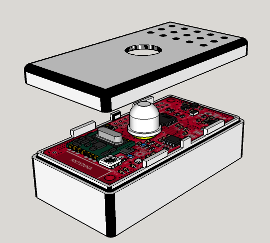
For the box
Is the battery kept away from the antenna part of the design. My question is is the board longer than an AA battery including battery "connectors" -
If you have space issues i think you should go for 0402 size, its not that hard to solder if you have a magnifing lamp, a good soldering iron, a tweezers and some thin soldering iron :)
-
Yep I have already all these tools ;)
I have already soldered 0402, for sensebender for instance :) I ordered 3 boards at oshpark, couldn't wait! It works well.
But when I can, I prefer 0805, or 0603 min. My way to share. 0402, not everyone will try, nor 805 I know..! And I prefer to minimize mistake source , less small things, less error possibilities at prototyping. I could have choosed atmel vqfn too!
I like when I see someone sharing 0603/0805 files. When I see something 0402 and really need it, I make it 0805/0603 ;)
For this board I think 0603 min is ok. For the moment it's 0805, I will try to add a little bit more clearance before ordering it.
It could be a little bit smaller with 0402, but not much, there are antenna area, and battery connector, components on top... And between a 6 or 6.5cm pcb...hum is it really useful, I am far away of coincell size so! And I don't want to put radio on bottom, between the pcb and battery holder. it would add more thickness.Sensebender is a very special case, a challenge. It is the ultra mini sensor board. but no batt holder. Add it and a box, it's not the same size. There are minimal
Hello! It looks like you're interested in this conversation, but you don't have an account yet.
Getting fed up of having to scroll through the same posts each visit? When you register for an account, you'll always come back to exactly where you were before, and choose to be notified of new replies (either via email, or push notification). You'll also be able to save bookmarks and upvote posts to show your appreciation to other community members.
With your input, this post could be even better 💗
Register Login