Skip to content
  • MySensors
  • OpenHardware.io
  • Categories
  • Recent
  • Tags
  • Popular
Skins
  • Light
  • Brite
  • Cerulean
  • Cosmo
  • Flatly
  • Journal
  • Litera
  • Lumen
  • Lux
  • Materia
  • Minty
  • Morph
  • Pulse
  • Sandstone
  • Simplex
  • Sketchy
  • Spacelab
  • United
  • Yeti
  • Zephyr
  • Dark
  • Cyborg
  • Darkly
  • Quartz
  • Slate
  • Solar
  • Superhero
  • Vapor

  • Default (No Skin)
  • No Skin
Collapse
Brand Logo
  1. Home
  2. Hardware
  3. Removing pro mini led bricked the board

Removing pro mini led bricked the board

Scheduled Pinned Locked Moved Hardware
atmega328pbattery poweredpower ledpro mini
15 Posts 8 Posters 7.5k Views 7 Watching
  • Oldest to Newest
  • Newest to Oldest
  • Most Votes
Reply
  • Reply as topic
Log in to reply
This topic has been deleted. Only users with topic management privileges can see it.
  • tripyT Offline
    tripyT Offline
    tripy
    wrote on last edited by
    #1

    Hello,

    following the "General Tips for Battery Operation", I tried to remove the power led in 2 of my pro mini 3.3V.
    One by removing the led (using a small screwdriver as lever) and another by cutting the mark leading to it.
    In both cases, this resulted in a board that didn't react anymore to my FTDI programmer.
    Both boards where able to be uploaded a simple DHT mysensors sketch prior to the operation.
    Evidently, they where not the boards linked from the mysensors pages, I had them from a previous project.
    If anyone wonder, this is where I got them: http://www.aliexpress.com/item/Free-Shipping-new-version-5pcs-lot-QFN-Pro-Mini-328-Mini-ATMEGA328-ATMEGA328P-MU-3-3V/32264277091.html

    They are obviously clones, and maybe this one doesn't support it, but I still am trying to find a way to get rid of this led.
    This got me thinking that I have a few ATmega328P-PU in a drawer.
    I'm pretty sure I did burn a bootloader on those, and they seem to be a perfect candidate to have 3.3V low power nodes in my network.
    Although, I barely see any occurrences of this solution on the web site or in the forums.
    Is there a reason for that, apart being maybe considered too advanced/complicated?
    I remember having issue in the past with DHT22 and those on breadboard, giving unreliable results, but I think it was linked to non stabilized power getting below 3V.

    I currently am wondering if I should continue with the pro mini boards, or switch to a simpler "boarduino" setup.
    And if anyone had a similar issue with removing the led, and could revive the board, I' all hears too.

    Thanks.
    Tripy.

    1 Reply Last reply
    0
    • sundberg84S Offline
      sundberg84S Offline
      sundberg84
      Hardware Contributor
      wrote on last edited by
      #2

      I have boards looking similar.
      I just use my solder iron and de-solder the led and voltage reg.
      When i tried to cut it ended with me destroying something because same result as you.

      Controller: Proxmox VM - Home Assistant
      MySensors GW: Arduino Uno - W5100 Ethernet, Gw Shield Nrf24l01+ 2,4Ghz
      MySensors GW: Arduino Uno - Gw Shield RFM69, 433mhz
      RFLink GW - Arduino Mega + RFLink Shield, 433mhz

      1 Reply Last reply
      1
      • tripyT Offline
        tripyT Offline
        tripy
        wrote on last edited by
        #3

        Thanks for the reply.
        I still have 2 units left, so I'll try one this evening.

        1 Reply Last reply
        0
        • sundberg84S Offline
          sundberg84S Offline
          sundberg84
          Hardware Contributor
          wrote on last edited by
          #4

          @tripy Good luck!

          Controller: Proxmox VM - Home Assistant
          MySensors GW: Arduino Uno - W5100 Ethernet, Gw Shield Nrf24l01+ 2,4Ghz
          MySensors GW: Arduino Uno - Gw Shield RFM69, 433mhz
          RFLink GW - Arduino Mega + RFLink Shield, 433mhz

          1 Reply Last reply
          0
          • dark-nicoD Offline
            dark-nicoD Offline
            dark-nico
            wrote on last edited by
            #5

            I've the same model, and I used the same method as @sundberg84 (de-soldering led and reg).
            It works fine.
            I've never tested to cut the tracks.

            1 Reply Last reply
            0
            • bjacobseB Offline
              bjacobseB Offline
              bjacobse
              wrote on last edited by
              #6

              I use similar clones with success.
              BUT do NOT cut the wires, un-solder or just wipe off the electrical component. The PCB is routing a wire below the voltage regulator so cutting the wires with a knife will kill it. The cutting trick is ONLY valid on genuine Arduino Pro MIni boards

              1 Reply Last reply
              1
              • mfalkviddM Offline
                mfalkviddM Offline
                mfalkvidd
                Mod
                wrote on last edited by
                #7

                I have also tried to cut the tracks which bricked my board. I now remove the led instead, which has worked for 10+ Arduino clones.

                1 Reply Last reply
                0
                • carlierdC Offline
                  carlierdC Offline
                  carlierd
                  wrote on last edited by
                  #8

                  Hello,

                  I usually desolder the regulator as it's not too difficult but now I did not desolder the LED. I prefer desolder the resistor before the LED. It's really easier !
                  At the beginning I was used to desolder the LED and damaged one card ...

                  David.

                  1 Reply Last reply
                  0
                  • tripyT Offline
                    tripyT Offline
                    tripy
                    wrote on last edited by tripy
                    #9

                    Thank you all for chippin in.
                    I just desoldered the led on one of my last units, and it still boots afterward.
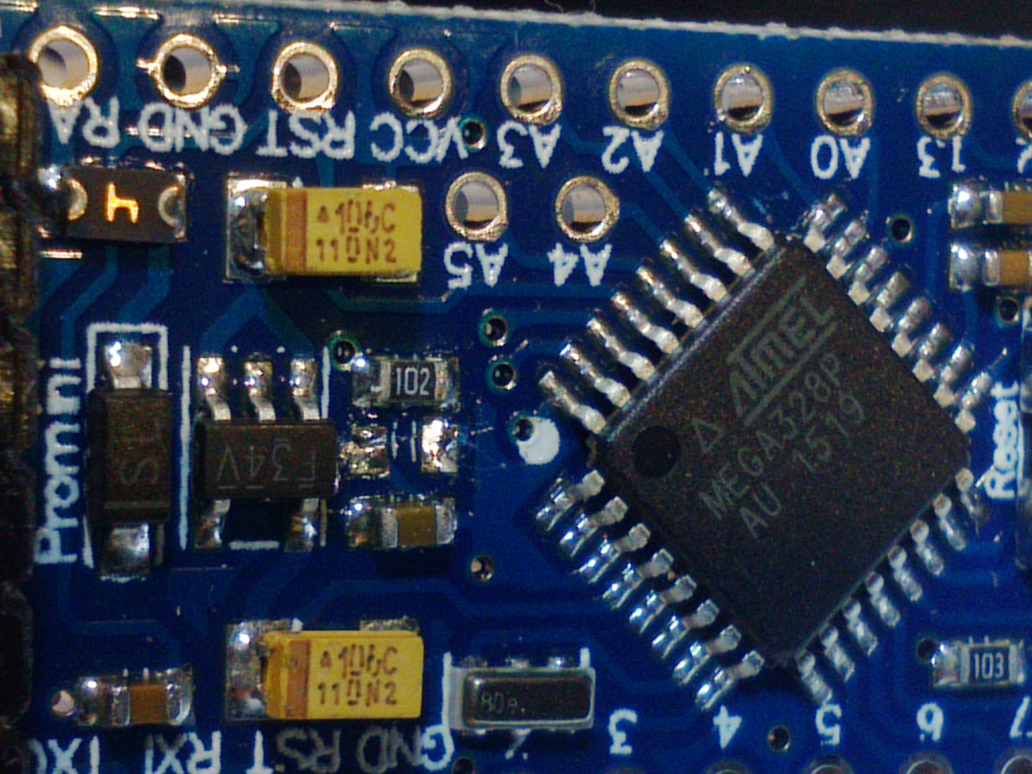
                    My sight and big fingers are sadly the biggest obstacle in this operation, but now at least I know it can be done.

                    I was able to take a macro shot, and effectively, I can see a track underneath the led.0_1456860485400_IMG_20160301_202411.jpg

                    I think I'll let the voltage stabilizer untouched, and continue to feed stabilized 3.3V through the VCC pin.
                    The led was my biggest concern for running the node on battery.

                    Thanks again everyone!

                    1 Reply Last reply
                    0
                    • carlierdC Offline
                      carlierdC Offline
                      carlierd
                      wrote on last edited by
                      #10

                      My advice: leave the LED and remove the resistor ! Really easier !

                      tripyT Igor KatkovI 2 Replies Last reply
                      0
                      • carlierdC carlierd

                        My advice: leave the LED and remove the resistor ! Really easier !

                        tripyT Offline
                        tripyT Offline
                        tripy
                        wrote on last edited by
                        #11

                        @carlierd Is the resistore the element marqued 102 above the led? And I don't see how this is easier.
                        My biggest issue was to put my pliers between the led and the adjacent element and not have the magnifying glass move too much while applying the iron tip on the side of the led.

                        1 Reply Last reply
                        0
                        • carlierdC Offline
                          carlierdC Offline
                          carlierd
                          wrote on last edited by
                          #12

                          Yes it is the resistor.
                          I don't why it's easier but it is ;) Probably because heat propagation is better.

                          tripyT 1 Reply Last reply
                          0
                          • carlierdC carlierd

                            Yes it is the resistor.
                            I don't why it's easier but it is ;) Probably because heat propagation is better.

                            tripyT Offline
                            tripyT Offline
                            tripy
                            wrote on last edited by tripy
                            #13

                            @carlierd Ok, I have a couple more in the mail, I'll try this for the next batch. Thanks.

                            1 Reply Last reply
                            0
                            • carlierdC carlierd

                              My advice: leave the LED and remove the resistor ! Really easier !

                              Igor KatkovI Offline
                              Igor KatkovI Offline
                              Igor Katkov
                              wrote on last edited by
                              #14

                              I think @carlierd means that resistor '102' (1kOmh) is serially connected with led. It's also on the side so removing it much easier - you just heat one side and push then another side and push away. In the reference design I think this 102 is actually R11.
                              Correct me if I'm wrong.

                              1 Reply Last reply
                              0
                              • Thomas NordquistT Offline
                                Thomas NordquistT Offline
                                Thomas Nordquist
                                wrote on last edited by
                                #15

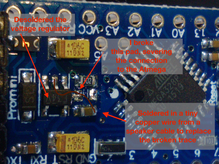
                                I decided to fix the broken trace I so naively destroyed while breaking the power LED out with a screwdriver. The image from @tripy really helped to figure out which trace I actually broke. It helped a lot to desolder the voltage regulator as well, leaving me with pads I can solder to. I left the regulator out after the repair since I am running the thing from 5V USB.

                                With the regulator out of the way the correct pad was easily identified.

                                Maybe someone else finds this useful, definitly saved my kitchen lighting project today :blush:

                                0_1509309184338_1456860488412-img_20160301_202411.jpg

                                1 Reply Last reply
                                2
                                Reply
                                • Reply as topic
                                Log in to reply
                                • Oldest to Newest
                                • Newest to Oldest
                                • Most Votes


                                24

                                Online

                                11.7k

                                Users

                                11.2k

                                Topics

                                113.0k

                                Posts


                                Copyright 2019 TBD   |   Forum Guidelines   |   Privacy Policy   |   Terms of Service
                                • Login

                                • Don't have an account? Register

                                • Login or register to search.
                                • First post
                                  Last post
                                0
                                • MySensors
                                • OpenHardware.io
                                • Categories
                                • Recent
                                • Tags
                                • Popular