'MySensoring' an Intermatic EH40 (Project Completed!)
-
I was going to try and build a control for my water heater from the ground up, but then it occurred to me why not try and 'MySensor' an existing EH40 control?
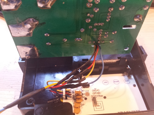
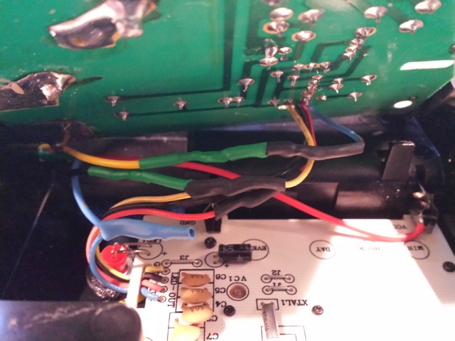
So I tore mine apart and this is what I observed.
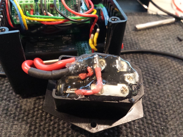
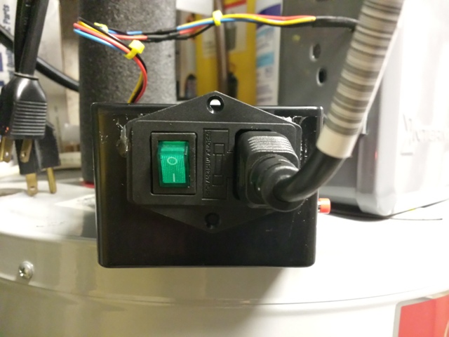
There are 2 control boards, One appears to be the 'high voltage' board, the other the 'logic' board. 4 control Wires connect them both.
High Voltage Board:
- 2 Relays, both with 43vdc coil voltage. (No other relays)
- Power for the front panel LED seems to come from this board.
- The control circuit that drives those relays is VERY sensitive. Simply touching the blue wire with my finger causes the relays to activate.
Logic Board:
- The logic board is powered by a single AA battery.
- This single battery also supplies the voltage to trip the relay drive circuit on the HV Board.
- The control circuit current draw for driving the relay circuit. is 1.9uA.
- This battery has powered the control for 2 years, so the circuit seems to be VERY efficient.
Logic Board Wires:
- Blue wire provides the power to trip the relay circuit.
- Red and Black wires appears to power the front panel LED (LED is part of this board, but power seems to come from the HV Board)
- Yellow wire is GND
I want to 'control' the blue wire with the most efficient means so I can power MySensors with it's normal power.
Questions:
- How do I accomplish this efficient switching?
- How do I monitor the power signal coming FROM my switching circuit to feed that back to Vera (For status)?
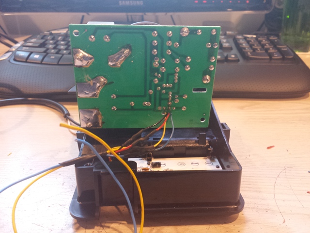
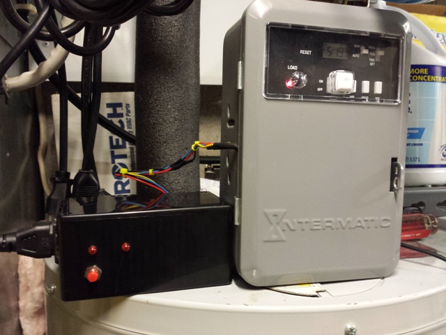
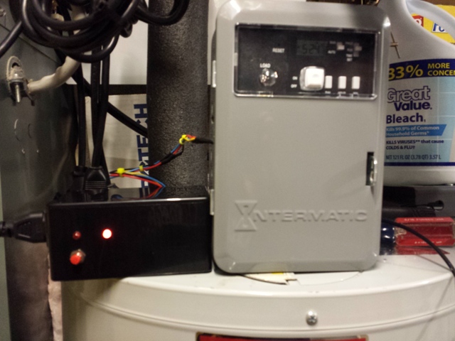
Pictures:
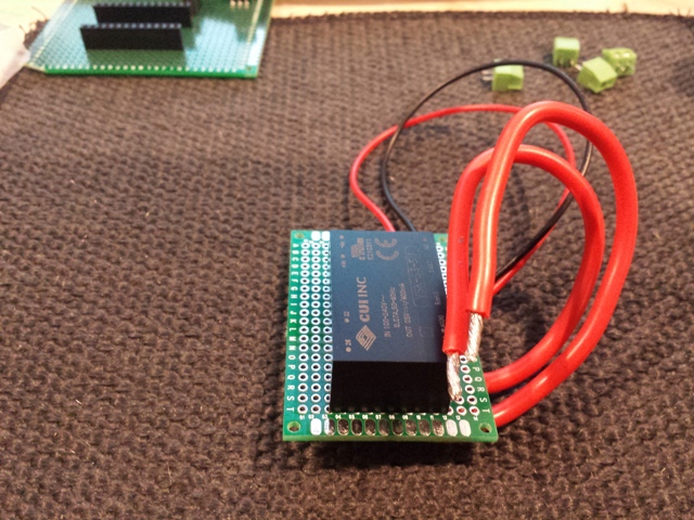
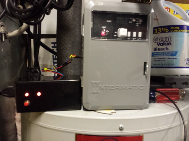
I split the blue wire after the first 3 pics (You will see the red wire (3rd wire) in the last pic)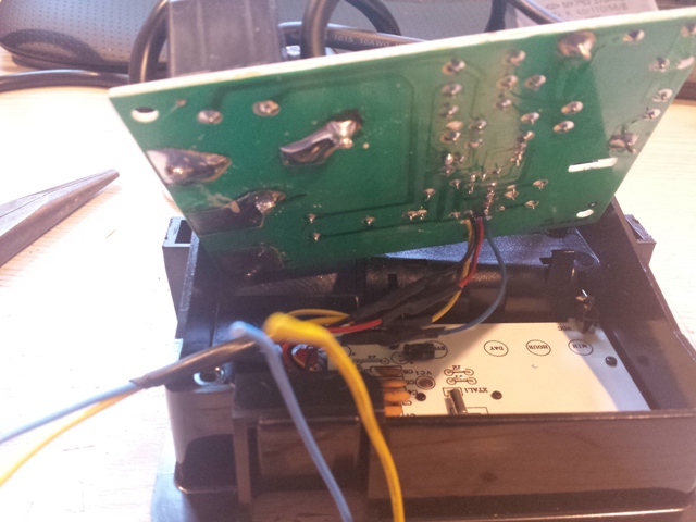
-
A relay actuator would work, I cant help so much with your question. But I want you to think some about safety also. Do not skip over safety components like over temperature and such. This could lead to a disaster. So basically 3 safety-steps:
Software at controller to regulate and send start / stop and read temperatures.
Software at relay-node to verify sane operating temperatures
and third - The absolutely most important - Hardwired safety temperature thermostat in case everything fails. (could be the relay fried stuck on i.e)write a principal scheme for better explanation!
-
Thinking out loud...... , Do I really need to use a transistor or relay to do the switching?
With only needing a 1.5vdc @ 1.9uA signal to cause the EH40 to turn the relays on, can I do this solely using the Arduino board?
Example:
Analog input to sense when the EH40 makes it's own call to turn the water heater on.
AND IF Vera says OFF then do nothing, otherwise allow ON..... (Not sure how any of that would work)
Analog output to send the 1.5vdc @ 1.9uA signal to turn the water heater ON.
Hmmmm......
@ServiceXp Hmm, I don't really know but you might be able to use the out-pin on the arduino and a resistor, but its not really safe in case there are some leakage. I would get isolation with a optocoupler. they are really cheap to buy! Often found in broken electronics too. only to salvage! :)
-
Ok optocoupler would be pretty cool from what I've learned about them. However, it seems that most will wind up consuming more power (x8) then the 1.9uA for the relay trigger.
I think to start off I'm going to try a voltage divider (2x 10M ohms resisters) which I believe will take my ~3.3vdc to 1.65vdc with consumption @ 165 nA which seems very low.
-
Ok,
Working on the code for this Water Heater CNT, and I've run into a problem. I have a temp sensor in the loop which is causing problems with the relays activating. Any time a the temp changes, while I try to activate a relay it fails to activate. (because it's tied up with sending the temps???)
How do I code around this?
Here is V1 of the code.
// Example sketch showing how to control physical relays. // This example will remember relay state even after power failure. #include <MySensor.h> #include <SPI.h> #include <DallasTemperature.h> #include <OneWire.h> #include <Bounce2.h> //Standard #define BUTTON_PIN 3 // Arduino Digital I/O pin number for button #define RELAY_1 4 // Arduino Digital I/O pin number for first relay (second on pin+1 etc) #define NUMBER_OF_RELAYS 2 // Total number of attached relays #define RELAY_ON 0 // GPIO value to write to turn on attached relay #define RELAY_OFF 1 // GPIO value to write to turn off attached relay //EH40 #define BUTTON_RELAY_PIN 5 // Relay Attached to Button Control #define BUTTON_RELAY_LED_PIN 8 // On while in Super Control #define LOCKOUT_RELAY_LED_PIN 7 // On while EH40 Program is locked out #define BUTTON_RELAY_ID 2 // Child Attached to Button Control #define EH40_LOCK_OUT_RELAY_ID 1 // Child Attached to EH40 Lock out relay //Temperature #define ONE_WIRE_BUS 6 // Pin where dallas sensor is connected #define MAX_ATTACHED_DS18B20 16 Bounce debouncer = Bounce(); int BATTERY_SENSE_PIN = A0; // select the input pin for the EH40 battery sense point int oldBatteryPcnt = 0; int oldValue=0; bool state; //Temperature OneWire oneWire(ONE_WIRE_BUS); DallasTemperature sensors(&oneWire); float lastTemperature[MAX_ATTACHED_DS18B20]; int numSensors=0; boolean receivedConfig = false; boolean metric = false; MySensor gw; // Initialize Button message MyMessage msg(BUTTON_RELAY_ID,V_LIGHT); // Initialize temperature message MyMessage msgTEMP(0,V_TEMP); void setup() { // use the 1.1 V internal reference analogReference(INTERNAL); // Startup OneWire sensors.begin(); // Initialize library and add callback for incoming messages gw.begin(incomingMessage, AUTO, true); // Send the sketch version information to the gateway and Controller gw.sendSketchInfo("Water Heater CNT", "1.0"); // Fetch the number of attached temperature sensors numSensors = sensors.getDeviceCount(); // Setup the button pinMode(BUTTON_PIN,INPUT); // Activate internal pull-up digitalWrite(BUTTON_PIN,HIGH); // Then set LED relay pin in output mode pinMode(BUTTON_RELAY_LED_PIN, OUTPUT); // Then set LED Lockout relay pin in output mode pinMode(LOCKOUT_RELAY_LED_PIN, OUTPUT); //Set LED to off digitalWrite(BUTTON_RELAY_LED_PIN,HIGH); digitalWrite(LOCKOUT_RELAY_LED_PIN,HIGH); // After setting up the button, setup debouncer debouncer.attach(BUTTON_PIN); debouncer.interval(5); // Present all Temperature sensors to controller for (int i=0; i<numSensors && i<MAX_ATTACHED_DS18B20; i++) { gw.present(i, S_TEMP); } // Fetch relay status for (int sensor=1, pin=RELAY_1; sensor<=NUMBER_OF_RELAYS;sensor++, pin++) { // Register all sensors to gw (they will be created as child devices) gw.present(sensor, S_LIGHT); // Make sure relay is off when starting up digitalWrite(pin, RELAY_OFF); // Then set relay pins in output mode pinMode(pin, OUTPUT); // Set relay to last known state (using eeprom storage) digitalWrite(pin, gw.loadState(sensor)?RELAY_ON:RELAY_OFF); } } void loop() { // Alway process incoming messages whenever possible gw.process(); debouncer.update(); // Get the update value int value = debouncer.read(); if (value != oldValue && value==0) { //(value != oldValue && value==0) { gw.send(msg.set(msg.getBool()?false:true), true); // Store state in eeprom gw.saveState(msg.sensor, msg.getBool()); } oldValue = value; delay(1); //Send Temperatures to Controller sendTemperatureToController(); } void incomingMessage(const MyMessage &message) { // We only expect one type of message from controller. But we better check anyway. if (message.type==V_LIGHT) { // Change relay state digitalWrite(message.sensor-1+RELAY_1, message.getBool()?RELAY_ON:RELAY_OFF); // Store state in eeprom gw.saveState(message.sensor, message.getBool()); // Write some debug info Serial.print("Incoming change for sensor:"); Serial.print(message.sensor); Serial.print(", New status: "); Serial.println(message.getBool()); //Handle LED's ledControl(message.sensor); // Check EH40 Battery, but only when we receive work runBATTFuntion(); } } void ledControl(int isensor){ switch (isensor) { case BUTTON_RELAY_ID: if (gw.loadState(BUTTON_RELAY_ID) == RELAY_ON) { digitalWrite(BUTTON_RELAY_LED_PIN,HIGH); } else { digitalWrite(BUTTON_RELAY_LED_PIN,LOW); } break; case EH40_LOCK_OUT_RELAY_ID: if (gw.loadState(EH40_LOCK_OUT_RELAY_ID) == RELAY_ON) { digitalWrite(LOCKOUT_RELAY_LED_PIN,HIGH); } else { digitalWrite(LOCKOUT_RELAY_LED_PIN,LOW); } break; //Set to off digitalWrite(BUTTON_RELAY_LED_PIN,HIGH); digitalWrite(LOCKOUT_RELAY_LED_PIN,HIGH); } } void runBATTFuntion(){ // get the battery Voltage int sensorValue = analogRead(BATTERY_SENSE_PIN); Serial.println(sensorValue); // 1M, 470K divider across battery and using internal ADC ref of 1.1V // Sense point is bypassed with 0.1 uF cap to reduce noise at that point // ((1e6+470e3)/470e3)*1.1 = Vmax = 3.44 Volts // 3.44/1023 = Volts per bit = 0.003363075 float batteryV = sensorValue * 0.003363075; int batteryPcnt = sensorValue / 10; Serial.print("Battery Voltage: "); Serial.print(batteryV); Serial.println(" V"); Serial.print("Battery percent: "); Serial.print(batteryPcnt); Serial.println(" %"); if (oldBatteryPcnt != batteryPcnt) { // Power up radio after sleep gw.sendBatteryLevel(batteryPcnt); oldBatteryPcnt = batteryPcnt; } } void sendTemperatureToController(){ // Fetch temperatures from Dallas sensors sensors.requestTemperatures(); // Read temperatures and send them to controller for (int i=0; i<numSensors && i<MAX_ATTACHED_DS18B20; i++) { // Fetch and round temperature to one decimal //float temperature = static_cast<float>(static_cast<int>((sensors.getTempFByIndex(i)) * 10.)) / 10.; float temperature = static_cast<float>(static_cast<int>((gw.getConfig().isMetric?sensors.getTempCByIndex(i):sensors.getTempFByIndex(i)) * 10.)) / 10.; // Only send data if temperature has changed and no error if (lastTemperature[i] != temperature && temperature != -127.00) { // Send in the new temperature gw.send(msgTEMP.setSensor(i).set(temperature,1)); lastTemperature[i]=temperature; } } } -
Solved the 'asynchronous' issue thanks Google and a gazillion other having the same question... :-)
So here is version 2.
Here is the framework for the code below.
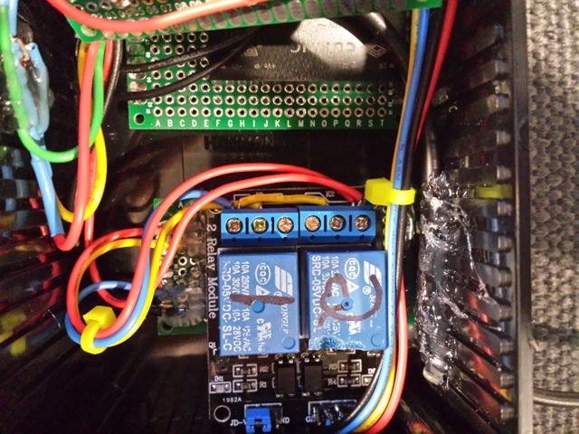
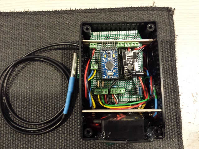
Current Hardware:
It incorporates a dual relay , Intermatic EH40 220v Timer, Temperature Sensor, 1 LED for visual indication of power ON state for each of the relays, and a simple momentary push button. (outside of the 5v Mini Pro)Waiting on Items:
Transformer, fused rocker switch
Need to Decide:
An appropriate enclosure, and if I'm going to add an enclosure temp sensor. I was thinking since I'm going to have a transformer and relay assm., possibly inside a plastic enclosure It might be a good ideal to protect against heat..Schema:
-
The EH40_LOCK_OUT_RELAY_ID locks out the EH40 relay drive circuit and is wired to the NC contacts of relay 1. (So if there is a Arduino failure, the timer will still run it's schedule)
-
The BUTTON_RELAY_ID is a Master Control Relay and will allow 1) overriding of the EH40 relay drive circuit and is wired to the NO contacts of relay 2.
-
Power for the EH40 relay circuit is routed out of the EH40, through the relays and back to the EH40. So all drive power is coming from the EH40 single AA battery. The hardware and code supports monitoring the EH40 battery supply. This will keep the 2 power supplies completely isolated.
-
Added the DS18B20 temperature sensor to report back tank temp. for controller logic (VERA) I have some idea's on what I may want to do with this.
-
Push button that controls the Master Control Relay. This allows us to manually turn on the water heater when near the unit.
I'm sure I've forgot stuff, but I'll follow up on this project as it progresses.
// Example sketch showing how to control physical relays. // This example will remember relay state even after power failure. #include <MySensor.h> #include <SPI.h> #include <DallasTemperature.h> #include <OneWire.h> #include <Bounce2.h> //Standard #define BUTTON_PIN 3 // Arduino Digital I/O pin number for button #define RELAY_1 4 // Arduino Digital I/O pin number for first relay (second on pin+1 etc) #define NUMBER_OF_RELAYS 2 // Total number of attached relays #define RELAY_ON 0 // GPIO value to write to turn on attached relay #define RELAY_OFF 1 // GPIO value to write to turn off attached relay //EH40 #define BUTTON_RELAY_PIN 5 // Relay Attached to Button Control #define BUTTON_RELAY_LED_PIN 8 // On while in Super Control #define LOCKOUT_RELAY_LED_PIN 7 // On while EH40 Program is locked out #define BUTTON_RELAY_ID 2 // Child Attached to Button Control #define EH40_LOCK_OUT_RELAY_ID 1 // Child Attached to EH40 Lock out relay //Temperature #define ONE_WIRE_BUS 6 // Pin where dallas sensor is connected #define MAX_ATTACHED_DS18B20 16 Bounce debouncer = Bounce(); int BATTERY_SENSE_PIN = A0; // select the input pin for the EH40 battery sense point int oldBatteryPcnt = 0; int oldValue=0; //Temperature OneWire oneWire(ONE_WIRE_BUS); DallasTemperature sensors(&oneWire); float lastTemperature[MAX_ATTACHED_DS18B20]; unsigned long TemperatureTimeing; const unsigned long Temperatureinterval = 30000; //30 sec int numSensors=0; boolean receivedConfig = false; boolean metric = false; MySensor gw; // Initialize Button message MyMessage msg(BUTTON_RELAY_ID,V_LIGHT); // Initialize temperature message MyMessage msgTEMP(0,V_TEMP); void setup() { //Initialize Temperature Timer TemperatureTimeing = millis (); // use the 1.1 V internal reference analogReference(INTERNAL); // Startup OneWire sensors.begin(); // Initialize library and add callback for incoming messages gw.begin(incomingMessage, AUTO, true); // Send the sketch version information to the gateway and Controller gw.sendSketchInfo("Water Heater CNT", "1.0"); // Fetch the number of attached temperature sensors numSensors = sensors.getDeviceCount(); // Setup the button pinMode(BUTTON_PIN,INPUT); // Activate internal pull-up digitalWrite(BUTTON_PIN,HIGH); // Then set LED relay pin in output mode pinMode(BUTTON_RELAY_LED_PIN, OUTPUT); // Then set LED Lockout relay pin in output mode pinMode(LOCKOUT_RELAY_LED_PIN, OUTPUT); //Set LED to off digitalWrite(BUTTON_RELAY_LED_PIN,HIGH); digitalWrite(LOCKOUT_RELAY_LED_PIN,HIGH); // After setting up the button, setup debouncer debouncer.attach(BUTTON_PIN); debouncer.interval(5); // Present all Temperature sensors to controller for (int i=0; i<numSensors && i<MAX_ATTACHED_DS18B20; i++) { gw.present(i, S_TEMP); } // Fetch relay status for (int sensor=1, pin=RELAY_1; sensor<=NUMBER_OF_RELAYS;sensor++, pin++) { // Register all sensors to gw (they will be created as child devices) gw.present(sensor, S_LIGHT); // Make sure relay is off when starting up digitalWrite(pin, RELAY_OFF); // Then set relay pins in output mode pinMode(pin, OUTPUT); // Set relay to last known state (using eeprom storage) digitalWrite(pin, gw.loadState(sensor)?RELAY_ON:RELAY_OFF); } } void loop() { // Alway process incoming messages whenever possible gw.process(); debouncer.update(); // Did the button get pushed? ButtonPushed(); if ( (millis () - TemperatureTimeing) >= Temperatureinterval) //Send Temperatures to Controller sendTemperatureToController(); } void incomingMessage(const MyMessage &message) { // We only expect one type of message from controller. But we better check anyway. if (message.type==V_LIGHT) { // Change relay state digitalWrite(message.sensor-1+RELAY_1, message.getBool()?RELAY_ON:RELAY_OFF); // Store state in eeprom gw.saveState(message.sensor, message.getBool()); // Write some debug info Serial.print("Incoming change for sensor:"); Serial.print(message.sensor); Serial.print(", New status: "); Serial.println(message.getBool()); //Handle LED's ledControl(message.sensor); // Check EH40 Battery, but only when we have received work runBATTFuntion(); } } void ButtonPushed(){ debouncer.update(); // Get the update value int value = debouncer.read(); if (value != oldValue && value==0) { //(value != oldValue && value==0) { gw.send(msg.set(msg.getBool()?false:true), true); // Store state in eeprom gw.saveState(msg.sensor, msg.getBool()); } oldValue = value; } void ledControl(int isensor){ switch (isensor) { case BUTTON_RELAY_ID: if (gw.loadState(BUTTON_RELAY_ID) == RELAY_ON) { digitalWrite(BUTTON_RELAY_LED_PIN,HIGH); } else { digitalWrite(BUTTON_RELAY_LED_PIN,LOW); } break; case EH40_LOCK_OUT_RELAY_ID: if (gw.loadState(EH40_LOCK_OUT_RELAY_ID) == RELAY_ON) { digitalWrite(LOCKOUT_RELAY_LED_PIN,HIGH); } else { digitalWrite(LOCKOUT_RELAY_LED_PIN,LOW); } break; //Set to off digitalWrite(BUTTON_RELAY_LED_PIN,HIGH); digitalWrite(LOCKOUT_RELAY_LED_PIN,HIGH); } } void runBATTFuntion(){ // get the battery Voltage of the EH40 int sensorValue = analogRead(BATTERY_SENSE_PIN); Serial.println(sensorValue); // 1M, 470K divider across battery and using internal ADC ref of 1.1V // Sense point is bypassed with 0.1 uF cap to reduce noise at that point // ((1e6+470e3)/470e3)*1.1 = Vmax = 3.44 Volts // 3.44/1023 = Volts per bit = 0.003363075 1.5v 0.001466276 float batteryV = sensorValue * 0.001466276; int batteryPcnt = sensorValue / 10; Serial.print("Battery Voltage: "); Serial.print(batteryV); Serial.println(" V"); Serial.print("Battery percent: "); Serial.print(batteryPcnt); Serial.println(" %"); if (oldBatteryPcnt != batteryPcnt) { // Power up radio after sleep gw.sendBatteryLevel(batteryPcnt); oldBatteryPcnt = batteryPcnt; } } void sendTemperatureToController(){ //Start time for Temperature readings TemperatureTimeing = millis (); // Fetch temperatures from Dallas sensors sensors.requestTemperatures(); // Read temperatures and send them to controller for (int i=0; i<numSensors && i<MAX_ATTACHED_DS18B20; i++) { // Fetch and round temperature to one decimal //float temperature = static_cast<float>(static_cast<int>((sensors.getTempFByIndex(i)) * 10.)) / 10.; float temperature = static_cast<float>(static_cast<int>((gw.getConfig().isMetric?sensors.getTempCByIndex(i):sensors.getTempFByIndex(i)) * 10.)) / 10.; // Only send data if temperature has changed and no error if (lastTemperature[i] != temperature && temperature != -127.00) { // Send in the new temperature gw.send(msgTEMP.setSensor(i).set(temperature,1)); lastTemperature[i]=temperature; } } } -
-
So you incorporated a delay between sending your temp values to resolve the issue? Were you spamming the GW with messages without the delay?
Yes during temperature changes..
In the first iteration I was using delays of various times (the one posted in v1 of the code was setting the delay to 1 ms to basically shut it off instead of deleting the function), in an effort to resolve the asynchronous nature of this language.
The larger I made the delay the worse the problem became and that made sense because as I understand it, the delay function stops code execution. So in v2 I just incorporated a time component. So now it will only check temps every Temperatureinterval.
Not being a C programmer..... this stuff is like trying to pick up a greased watermelon seed while being chased by a hornet.. ;-)
but for now this works... for now.....
-
Project Complete! My EH40 has now been 'MySensored'
This was a fun project, and I learned quite a bit during the process and I was able to accomplish all my goals.
Goal Recap
- Remotely lockout the EH40's schedule.
- Remotely Activate the EH40 Relay.
- Locally override_to_On, Both Vera and the EH40 schedule (Button)
- Remotely acquire water heater's tank temperature.
Final Components Used:
- Arduino mini 5V
- Dual Relay 5V
- Couple of pcb's
- Screw Connectors
- Push Button
- Temperature Sensor
- Radio
8.) Step Down Module - Fused Rocker Switch
- Transformer I wound up going with one of these over the Ebay China option. Just felt more comfortable with this.
- Project Box
Misa: Resisters, 47uF cap for the radio, wires and lots of solder and hot glue.
**Final EH40 Wire Configuration **
- Red - 1.5vdc directly from EH40 Batt.
- Black (Yellow) GND
- Blue (Blue) Input
- Yellow (Blue) Output
Transformer Assm: Board
The output seem stable enough (using a volt meter) I didn't use any post filtering.
All connection under pcb is covered in a thick layer of hot glue to help prevent any shorts.EH40 Connection Board
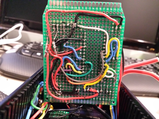
Main Control Board
I forgot to get pictures of the top, but here is the messy bottom..
EH40 Connection Board Mounted In Box
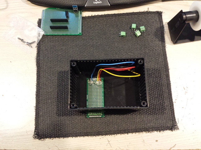
Using a Dremel; cut a slot out, then hot gluing to bottom of box.
Dual Relay Mounted

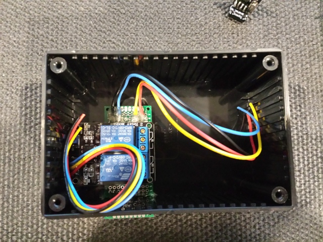
It was a perfect fit.
Push Button and LED (Wired Relay Contacts)
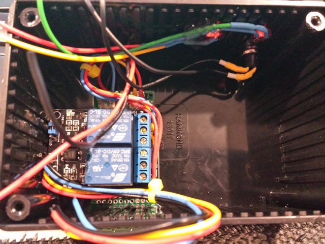
Top relay is #1 (Lockout); 2nd is #2 (Override)
1)Relay #1 -- Blue Wire -- Output to NC
2)Relay #1 -- Yellow Wire -- input to COM3)Relay #1 -- Blue Wire -- Output NC JUMPED to COM of Relay #2
4)Relay #2 -- 2 Red Wires (One from EH40 and the other for battery monitoring on Main Control Board) -- Output to NO
5)Relay #2 -- COM JUMPED to Relay #1 NCFused Power Switch and Socket
500ma Fuse with all exposed connection covered in hot glue.
Transformer; Relay; EH40 Connection and Main Board
I tried to keep the High Voltage section isolated from any of the low voltage section as best as possible.
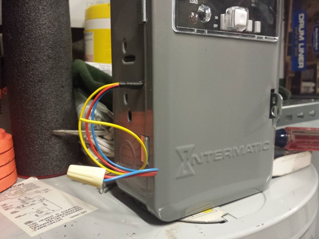
Completed Project Connected to EH40
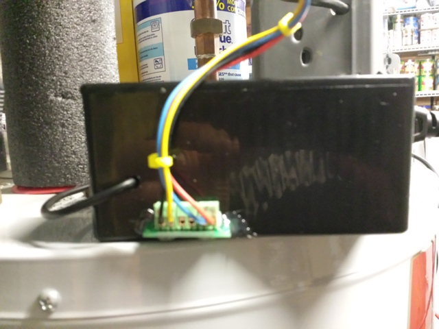
EH40 Connection
115vac Connection
EH40 Has Control and running it's schedule
Vera (Remote) has EH40 Schedule Locked Out (Water Heater Off)
Vera (Remote) has EH40 Schedule Locked Out but Override button is active (Water Heater On)
-
Update:
Wind up having to buy a oscilloscope to try and diagnose a problem I was having and wound up reworking the transformer board a little. I installed 5 caps in an attempt to clean up the output.
4.7uF/400V Cap between pins 22 and 26 on transformer. electrolytic
470uF/50v Between 5vd Output (electrolytic)
47uF/50v Between 5vd Output (electrolytic)
10uF/50v Between 5vd Output (electrolytic).1uF/ (ceramic) Installed at the screw connector on the main board (for best results)
Hello! It looks like you're interested in this conversation, but you don't have an account yet.
Getting fed up of having to scroll through the same posts each visit? When you register for an account, you'll always come back to exactly where you were before, and choose to be notified of new replies (either via email, or push notification). You'll also be able to save bookmarks and upvote posts to show your appreciation to other community members.
With your input, this post could be even better 💗
Register Login