💬 Sensebender Gateway
-
Depends on if they are active high, or active low.. In this case they where active low, so it actually was an error in the schematics, as it will writeprotect the flash chip.
@tekka please be aware of this, when you try to use the external flash in the bootloader on the dev board that I sent you..
@tbowmo
Thanks, in my case they are also active low, so I pull them to VCC. -
@tbowmo: thx for reply. Yes I have understood the same thing, so it should work... I will try with my stlink (st brand) asap I will receive my pcb.
Talking about stlink, I have just ordered this, very curious.. http://www.aliexpress.com/item/Free-shipping-1pcs-mini-ST-LINK-V2-ST-LINK-STLINK-STM8-STM32-emulator-download-super-protection/32600512506.html?spm=2114.01010208.3.1.1O5urT&ws_ab_test=searchweb201556_9,searchweb201602_1_505_506_503_504_10034_10020_502_10001_10002_10017_10010_10005_10006_10011_10003_10021_10004_10022_10009_10008_10018_10019,searchweb201603_3&btsid=0dfc1060-5064-466c-8071-ac0bab24a988
seriously??so cheap compared to some tools..if it can do the job, could be interesting!
There is also the nice IBDAP, cheap alternative to ice :
https://www.adafruit.com/products/2764
maybe you already know, I have not tested this yet, but seems very simple/useful tool:https://github.com/ataradov/edbg -
I've been using those cheap $3 ST-Link adapters for flashing ARM cortex chips with OpenOCD, using SWD pins. They're fantastic and work very well.
-
i really like this idea, i'm getting a bit tierd of having the mysensors gateway connected through a breadboard.
how far is it? i saw your comment that it is almost ready for last prototype, is this board fully functional?
Plus, will it be able to act as a Serial/Ethernet/MQTT gateway? or only 1 of these?And if it is ready, is there a place to order them, or just send the files to a PCB company?
-
I'm still waiting for the last prototype pcb's to arrive.
Depending on the sketch you load it with, it can be a serial, ethernet or MQTT gateway. It has native USB in the atsam, and a connector for a w5100 module.
Besides that it will have SD card for local storage of sensor data, so it could in theory operate without a controller at all..
@tbowmo Can you give some details about the final dimensions on the board? I want to start the woodworking on the casing for my current gateway. But I'll make sure your prototype fits in as well.
I can't wait 'till this one goes to production. Great work, I'm impressed.
-
The base board is 5x5 cm, but if you use nrf modules they will protrude over the edge of the PCB. Rfm69 is soldered to the bottom so they won't add to the dimensions. W5100 will probably make the base a few mm wider and longer (depending on the module..).
Design files are available at GH, so you can check the dimensions yourself -
The base board is 5x5 cm, but if you use nrf modules they will protrude over the edge of the PCB. Rfm69 is soldered to the bottom so they won't add to the dimensions. W5100 will probably make the base a few mm wider and longer (depending on the module..).
Design files are available at GH, so you can check the dimensions yourself@tbowmo Thanx for your fast reply. It's a great size. I'll create a mockup of it with cardboard. It'll give me a better visualization when I make the housing. Just a final question. I'm guessing I won't be able to stick an Arduino ethernet shield on it right?
-
-
Received a new prototype from dirtypcbs the other day
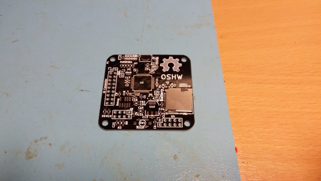
I have only come to the point where the SD Card reader is mounted, as I wanted to try the mechanics out :)
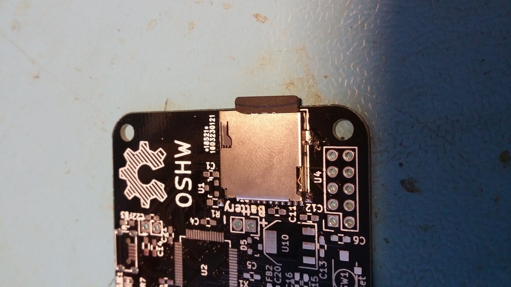
Currently I'm lacking time for finishing it within the next 2-3 weeks.. If someone knows how to slow down time around you, without being slowed down yourself, please tell me how to achieve it :) (Too many high priority tasks at the moment..)
-
Received a new prototype from dirtypcbs the other day
I have only come to the point where the SD Card reader is mounted, as I wanted to try the mechanics out :)
Currently I'm lacking time for finishing it within the next 2-3 weeks.. If someone knows how to slow down time around you, without being slowed down yourself, please tell me how to achieve it :) (Too many high priority tasks at the moment..)
Great design @tbowmo. Very interesting indeed.
I have some questions and suggestions if you don't mind.Will this support the use of the amplified version of the nrf24l01+ (NRF24L01* + PA + LNA). It uses a little more power than the non aplified version so It's even more sensirtive to power supply noise.
EDIT: In the schematic, upper left corner, in the ATSHA204 module it seems you have forgotten to add the SDA pin conection.
EDIT2: Haven't you thought in adding a battery charger module such as the TP4056. It would be nice to have this board woarking as its own UPS. Having the battery connected in the battery connector without something keeping the battery charged doesn't have much sense to me.
Regards!
-
It should have enough juice in the regulator to support an pa/lna enabled nrf24l01. I havent got one myself, so it's not "validated" yet.
The idea with the battery, is that it is only to keep the rtc alive in the atsam, and if you look at the schematics, then it's only the cpu that can be powered by battery. A coin cell battery should be enough. (I couldn't make room for a battery holder so that's why it just became a 2 pin header
The atsha204 is validated on the board, so it's working ;) If you look at the schematic, SDA pin on the atsha204 is labeled "SECURITY", pin 20 on the cpu is also labeled SECURITY, so these are connected.
-
Thanks @tbowmo. Now it's all clear.
What tests do you think are remaining in order to have the board fully tested and ready to production environement?
Regards! -
The only thing missing is the Ethernet module at the moment, it has been working on an earlier board, but can't get it working right now.
I'm almost at point where I will let our partner in China do their initial prototype spin, to evaluate production.
-
Received a new prototype from dirtypcbs the other day
I have only come to the point where the SD Card reader is mounted, as I wanted to try the mechanics out :)
Currently I'm lacking time for finishing it within the next 2-3 weeks.. If someone knows how to slow down time around you, without being slowed down yourself, please tell me how to achieve it :) (Too many high priority tasks at the moment..)
@tbowmo
In the series 12 Monkeys a scientist developed injections to slow down time at the quantum level, which allows you to be impervious to time shift. Not sure if it slows down time perception itself though. -
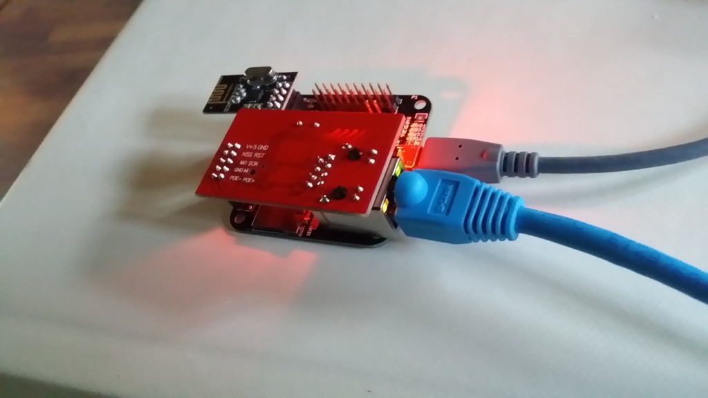
And ethernet is up!
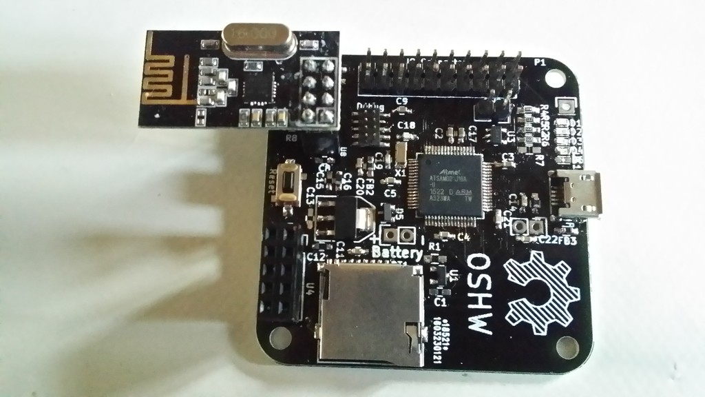
I think this calls for a couple of pictures of the "thing" :)
first with ethernet / usb (power) connected.
and without ethernet shield
Hi @tbowmo. Congratulations.
Have you identified what caused the trouble?
Regards!
Hello! It looks like you're interested in this conversation, but you don't have an account yet.
Getting fed up of having to scroll through the same posts each visit? When you register for an account, you'll always come back to exactly where you were before, and choose to be notified of new replies (either via email, or push notification). You'll also be able to save bookmarks and upvote posts to show your appreciation to other community members.
With your input, this post could be even better 💗
Register Login