Homini Complete Room Sensor Module?
-
Due to the electrochemical sensors being so hard to get my hands on it would seem i have very little choice but to order off of AliExpress.
I have found a decent price for the ME2-CO here: AliExpress.
I'm very tempted to get some normal MQ-7's just to try them out or even the high quality Figaro TGS2442's, but i just don't like the 24-48 Hour warm up period on those, that coupled with the power consumption is just putting me off of the 'normal' Semiconductor types. However, they are pretty cheap compared to the Electrochemicals.
Datasheets:
Questions
- Could i get some of your opinions on this, do you feel i'm being a little over the top with the power consumption issue?
- Whats your thoughts on the warm-up times? Don't forget they do apply when it comes to calibrating the sensor, you would have to make the calibration alterations, then wait another 2 days for it to warm and settle before testing again....
-
I've nearly compiled the full list of sensors for this module as follows:
- Carbon Monoxide Sensor - ME2-CO
- Smoke Sensor - 1 IR emitter & 1 Receiver to create a photoelectric sensor
- Humidity & Temp Sensor - SHT21
- Motion - HC-SR501 Module
- Light - APDS-9300-020
I'm now left with sourcing a low cost buzzer for this module and some LED's for status updates for debugging and notifications of working states. I'm tempted to have the device sleep with the smoke and carbon monoxide sensors connected to interrupt pins if possible and only have the motion sensor detecting in certain situations such as night time and alarm enabled status maybe. Its not something i want on permanently if not needed due to the current usage in busy areas such as hallways and main rooms, it will draw power consistently and the idea is to keep the power consumption down as low as possible.
As usual I appreciate all thoughts and suggestions for this and welcome them to the comments. I'm not the best at software/coding so if anyone would like to help in that aspect, i wouldn't say no when the time comes to do such a task. It will be a few weeks before that happens though as i'm yet to design the hardware. I need to purchase a few tools before this can go a head, including a hot air reflow station and a 3D printer for the custom case.
-
With all the parts for this module on order now, just for a discussion;
-
What would you hardware guys rather have in terms of ambient light sensors? Digital (I2C device) or Analogue that performs like a NPN transistor? What is easier to configure/setup? (APDS-9300-020 OR TEMT6000X01)
-
Low power motion detector daughter board or HC-SR501 Module?
-
I'm yet to make my voltage supply schematic, i'm looking at a few topics around here regarding this, does anyone have any information to educate me further in this area, power supply is not my most confident area ;)
-
-
Smoke Detector
I do plan on having footprints for both of the smoke detection methods, but this all depends on the space allowed on the PCB. If I can't have the footprint for both I will be making designs for both variations. On both of the designs, they will use the temperature sensor to create a 'hybrid' type of smoke detector so it isn't just smoke that it has to detect to trigger the fire warning.
Optical/Photoelectrical Method
I'm going down the route of creating my own optical sensor simply because I can not source a enclosed solution to put into my module. The only way around this would be to purchase cheap optical smoke detectors and remove the module and apply it to mine. Rather than doing this I would rather attempt to create my own solution using a IR Emitter LED and a IR Receiver.
However, to do this I need to have the IR LED pulsing at 38KHz. So this is where I'm feeling a 555 timer to come into play. Now I haven't done my research on a 555 timer but from what i understand the capacitor in the 555 circuit instructs the timer on the length of time the LED needs to be enabled, so this is what creates the 38KHz pulse. Please instruct me if I have this wrong. I'm then thinking that I could just monitor for smoke every 10 seconds or so to try and lower the consumption again. To do this would I just need to switch the trigger pin from low to high to make the output turn off therefor turning the LED off and then pull the trigger pin low to then turn the LED back on?
Ionisation Method
I'm very tempted to just use a MQ2 sensor with its circuit on my board rather than a separate board.
-
Motion Detection
Would you guys rather the motion detection be connected via a transistor so we can send messages to the node to enable and disable the motion side of the module rather than having motion being detected at all times? This isn't to save power (like a few of you that know me would assume) but more to enable us to only have it enabled at night in 'night time' mode to stop it from being triggered and sending messages back to the gateway constantly through every day life, in the main rooms of the house.
Look forward to hearing your inputs.
@Samuel235 said:
Motion Detection
Would you guys rather the motion detection be connected via a transistor so we can send messages to the node to enable and disable the motion side of the module rather than having motion being detected at all times?.
If not to save power, would not a software solution be easier and less complicated solution?
-
@Samuel235 said:
Motion Detection
Would you guys rather the motion detection be connected via a transistor so we can send messages to the node to enable and disable the motion side of the module rather than having motion being detected at all times?.
If not to save power, would not a software solution be easier and less complicated solution?
@Dwalt said:
@Samuel235 said:
Motion Detection
Would you guys rather the motion detection be connected via a transistor so we can send messages to the node to enable and disable the motion side of the module rather than having motion being detected at all times?.
If not to save power, would not a software solution be easier and less complicated solution?
You're correct in this scenario, however i've since decided to brong the power consumption as low as i can physically for two reasons; to bring the running costs of the module down as low as possible snd to allow me to adapt this board for use with batteries if ever it needed to.
-
@Dwalt said:
@Samuel235 said:
Motion Detection
Would you guys rather the motion detection be connected via a transistor so we can send messages to the node to enable and disable the motion side of the module rather than having motion being detected at all times?.
If not to save power, would not a software solution be easier and less complicated solution?
You're correct in this scenario, however i've since decided to brong the power consumption as low as i can physically for two reasons; to bring the running costs of the module down as low as possible snd to allow me to adapt this board for use with batteries if ever it needed to.
@Samuel235
I was under the assumption you intended this module to be always 'listening' to allow a controller to set it to night mode or 'disarm'. If so, battery power will be tricky. In addition, PIRs require a period of stabilization when powered on, often up to 30 seconds to calibrate sensor field of view background. -
@Samuel235
I was under the assumption you intended this module to be always 'listening' to allow a controller to set it to night mode or 'disarm'. If so, battery power will be tricky. In addition, PIRs require a period of stabilization when powered on, often up to 30 seconds to calibrate sensor field of view background.@Dwalt, you're right with the intention is to be listening all the time, and then therefor it would mean that sleeping the node for battery power is not going to work. However, i was planning to do this as a backup solution and then for incase i needed the feature. If this was needed to go to battery power it was able to switch off the motionI probably wont ever have a need for it, but its there if needed.
To go a step futher i could find a PIR Control IC, i remember reading somewhere that a fee controllers allow a PIR Sensor to be active when not even powered up. I might be wrong here but either way i understand your information regarding a warm up time on the motion module.
Thank you.
-
UPDATE
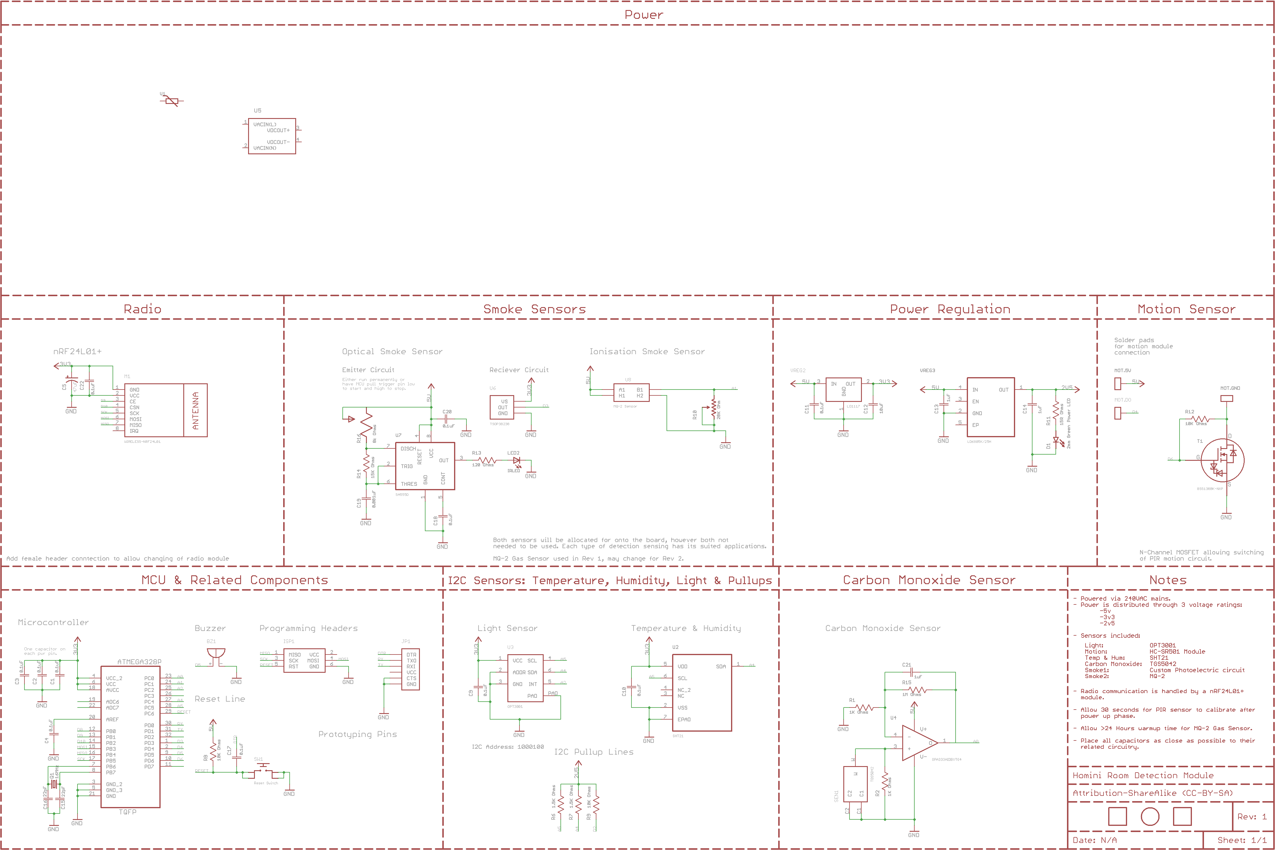
So then guys. I feel I have the sensing side of the board all designed out, I will include a schematic here for you to see. Just due to my inexperience of electronics still, i'm sure there will be a few faults/things you guys would like me to change around. Please point anything of any concern out to my attention and i will amend accordingly.
Sensors
Light: OPT3001
Motion: HC-SR501 Module
Temperature & Humidity: SHT21
Carbon Monoxide: TGS5042
Smoke1: Custom Photoelectric Circuit
Smoke2: MQ-2.The smoke sensors can both be fitted or one or the other. They will differ in applications, what area the module is being used in. They both detect different types of smoke/fires. I will included more detailed information on this for the release of the product.
Powering
I'm still yet to design the powering side of this, it will be 240VAC converted to 5VDC then regulated as and when needed. I Will include some way to externally power this module while we're programming it since it will draw more than i'm comfortable providing through a PC USB Socket. So there will be no VCC lines coming onto the board from the USB programmers, this way we can't cause any damage to your PC USB sockets/serial lines. I'm yet to work out the overall typical power consumption, which i do plan on calculating today so i can get the powering converters specified for the current needed.
Prototyping
If there is any pins left, currently have 5 pins (3 Analog and 2 Digital) left over, however i'm very tempted to have status LEDs on this module so therefor that will be 3 gone and will only leave possibly 2 empty analog pins. These will have VIAs located so we can use them for prototyping.
By no means is this schematic anywhere near completion, there may be floating connections or missing components. Please point them out if so.
Excuse the unfinished power circuit at the top of the schematic, this is where i've got to so far before i ran out of time. Currently just placed the varistor and the AC/DC Converter. Will keep updating as and when time allows.
-
This post is deleted!
-
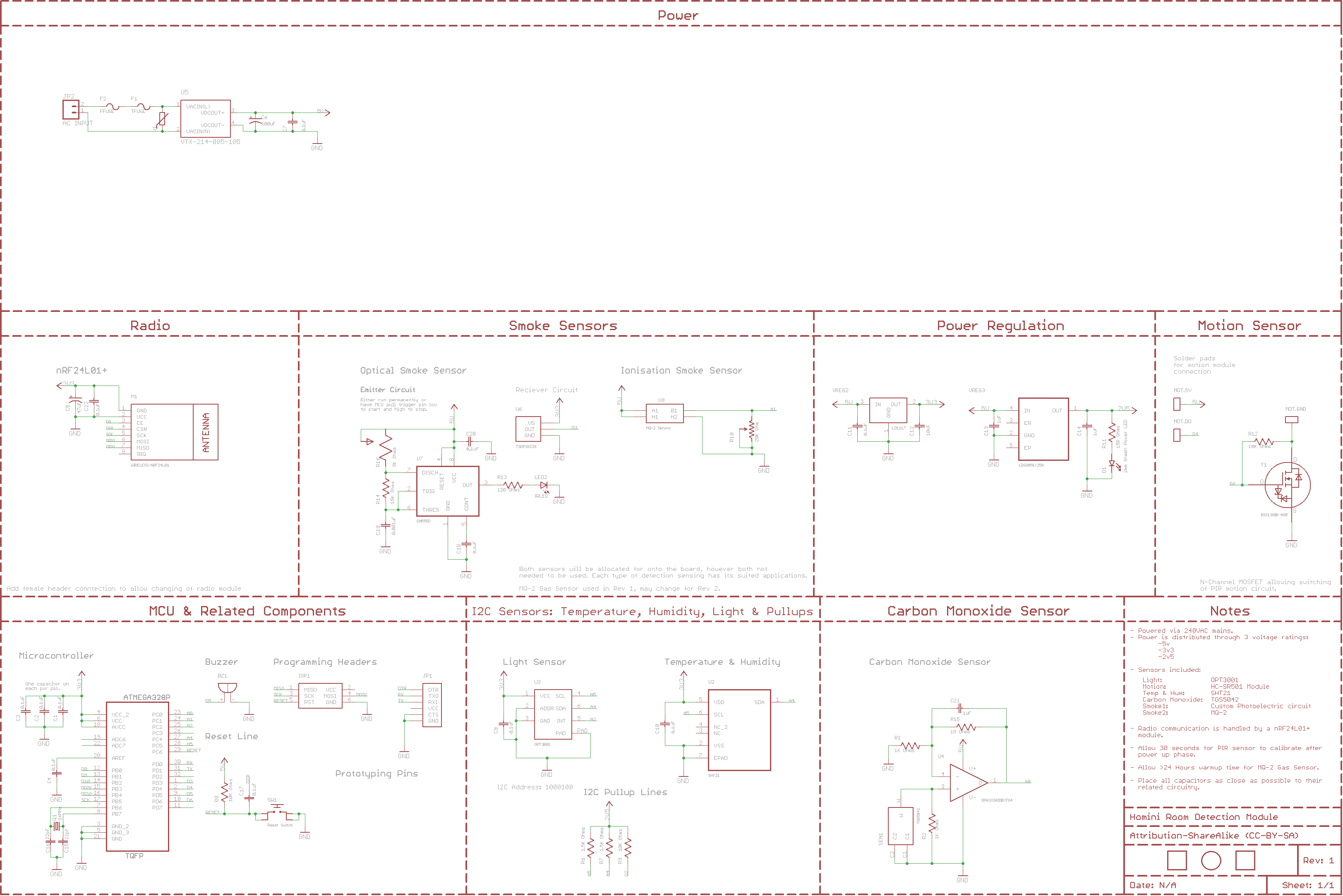
Updated the schematic in the post above. Please read the notes in bold above the image. Thanks.
-
Could i get some opinions regarding atmels signing IC's that we use for mysensor signing. Would you guys like this module to use that feature?
I may need some external flash for OTA firmware updates but i'm not sure if i want to include this on Rev1, maybe this is a Rev2 upgrade.
I doubt i will need any extra eeprom external from the amount built into the 328p mcu, we shall see about that when the software is made.
Lastly, is there any additional features that you guys would like to see implimented onto this module that you feel is missing? Any errors so far with the schematic you can see?
-
Another little bit of progress. I'm really struggling with time at the moment, had another 15 minutes to get some schematics done today. The power circuitry is coming along now, just the external programming power to sort out.
-
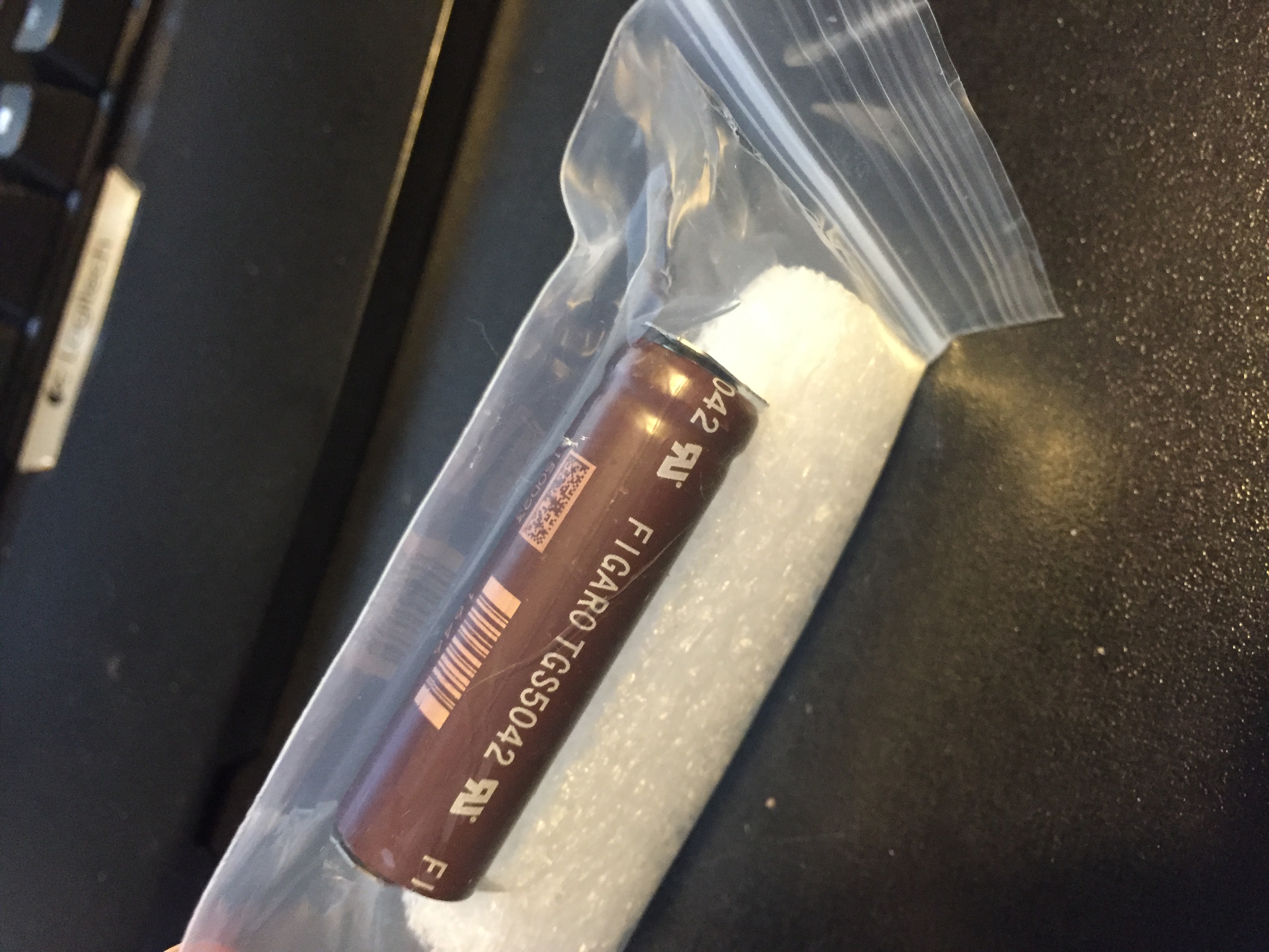
And the first of many to arrive is the Figaro Carbon Monoxide sensor.
-
There is a topic (here) being discussed regarding the use of IR LEDs and receivers to determine the circuit needed before i get some hardware. I will be ordering parts before the end of this week so if there is no suggestions i will be purchasing materials to trial and test the best setup for this.
Another subject to be discussed is powering while programming. I do propose to have the module fully powered up while programming and debugging to allow the monitoring of the sensor readings to allow debugging methods to be carried out with the best precision possible. However, this means that we need to have some sort of external connector on board to provide power while we're plugged into our programming systems. There would be two ways to go around this, one will allow full powered up mode for the board and the other will just allow power to the MCU and Radio while programming.
- Add external connector (I'm feeling maybe a USB Mini-B simply due to its popularity). This would then power up the board completely while programming is completed, allowing full debug viewing through serial monitor.
- Add a jumper on the power line of the MCU and Radio module to allow the programmer to provide enough power for the MCU and Radio while programming. This would mean that the only debugging we can do through the serial monitor would be MCU and Radio related.
Any input would be greatly appreciated.
-
The remaining parts have been ordered to get the prototyping under way. Plan of attack will be:
- Prototype each circuit on breadboards separately to make sure each is working as intended and giving the correct results.
- Combine all of the circuitry apart from the powering options onto breadboard as one working module, get some software written up with the help of a few guides, tutorials and a fellow member of our community being interested in joining me on this module.
- Generate PCB designs and have them manufactured.
- Test the AC/DC conversion circuitry for a few weeks while the PCB is on order.
- Receive the PCBs and populate with the breadboarded circuit.
- Fashion some sort of enclosure, hoping to have purchased a 3d printer by then.
Does anyone have any experience with a prusa I3 3d printer?
-
Infrared smoke detection circuitry has changed now. It is now going to running as a single IR LED coming from the MCU pin since we do not need any sort of frequency for a newly implemented photo transistor rather than the IR receiver. However, I may have it coming through the 555 time to just turn the LED on for 1 second every 10 seconds or so to stop excessive power draw for no reason. If it detects smoke 10 seconds later than it was first present inside of the chamber, that is fine for the needs of a smoke detector. In my opinion. If you feel otherwise please state so!
I have chosen to do this outside of software to save having to do multitasking in software. This way all that the MCU needs to know is if the photo transistor has detected any smoke, which we can monitor on every loop of the MCU.
I'm still not sure whether to go down the 555 timer route for the siren to sound or to use some soft of PWM function on the MCU. The way i'm thinking is that if we go down the timer route it releaves the MCU of another job and therefor it doesn't have to stall in the loop while its powering the buzzer. However, I personally feel that if the module detects smoke, the last thing that we will be worried about is if its taking readings from the other sensors. But then that would be a cool feature to be able to look back at the measurements on.
-
I would like to separate the 3v3 to the MCU and the radio from the rest of the components, this way i can safely power the MCU and Radio with the programmer when uploading software with just the programmer attached. But i want it so if it is powered externally i would like the board to use that power.
I'm proposing the use of diode(s) on the power lines in between the MCU and radio to stop the flow going out to the rest of the circuit. I'm hoping that by using the diode(s) to stop the 3v3 from the programming feeding to the whole 3v3 circuit it will not draw enough current to damage the programmer and the PC. By using this diode i believe that the MCU and Radio will draw the strongest voltage of whatever is connected, if nothing is connected other than the FTDI or ISP programmer then it will only power on the MCU and Radio. A quick hand drawn sketch below:
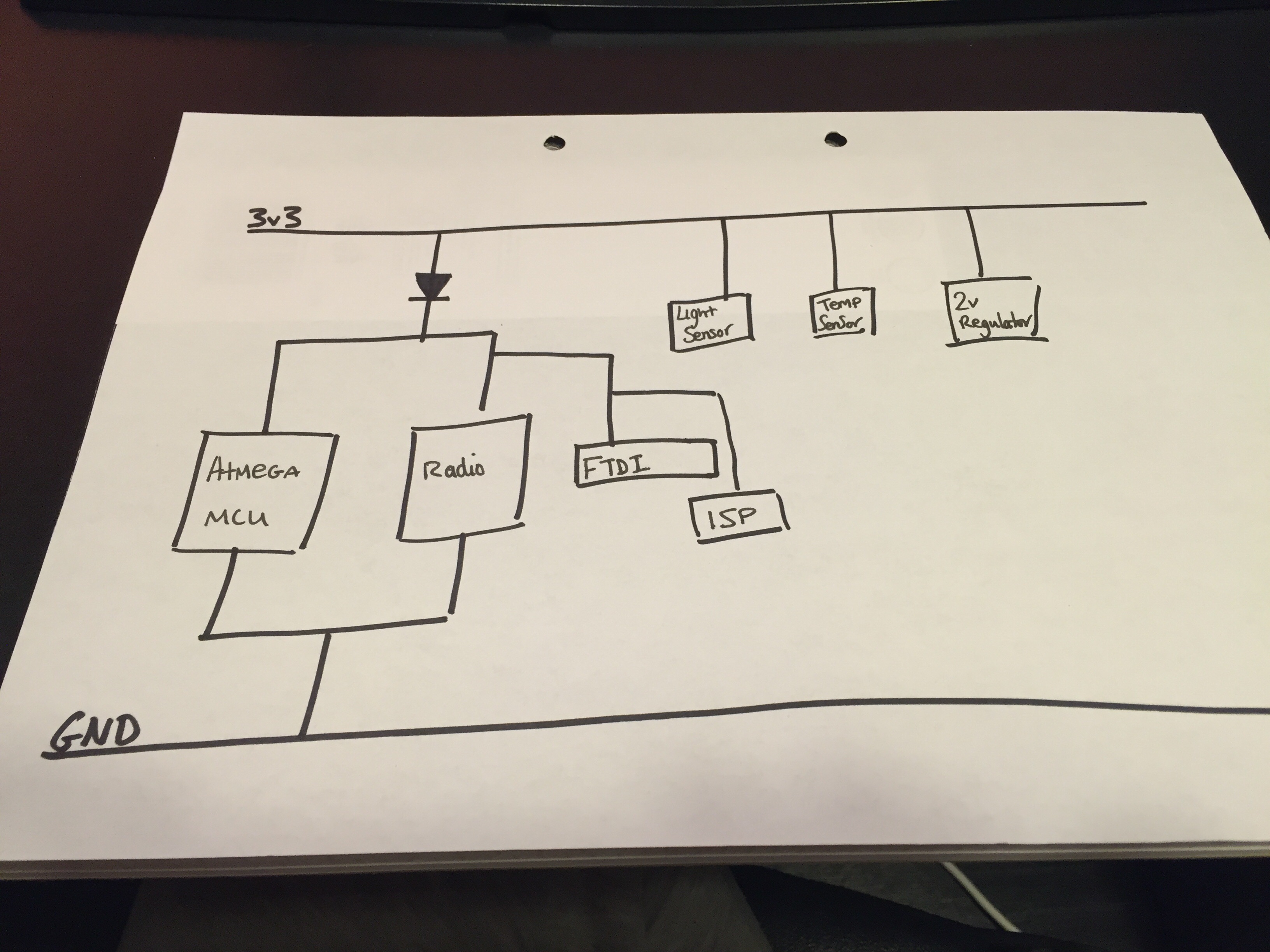
Do you feel i'm going about this the correct way rather than separating the MCU and radio with a hardware jumper? One less thing to care about while programming in my opinion.
-
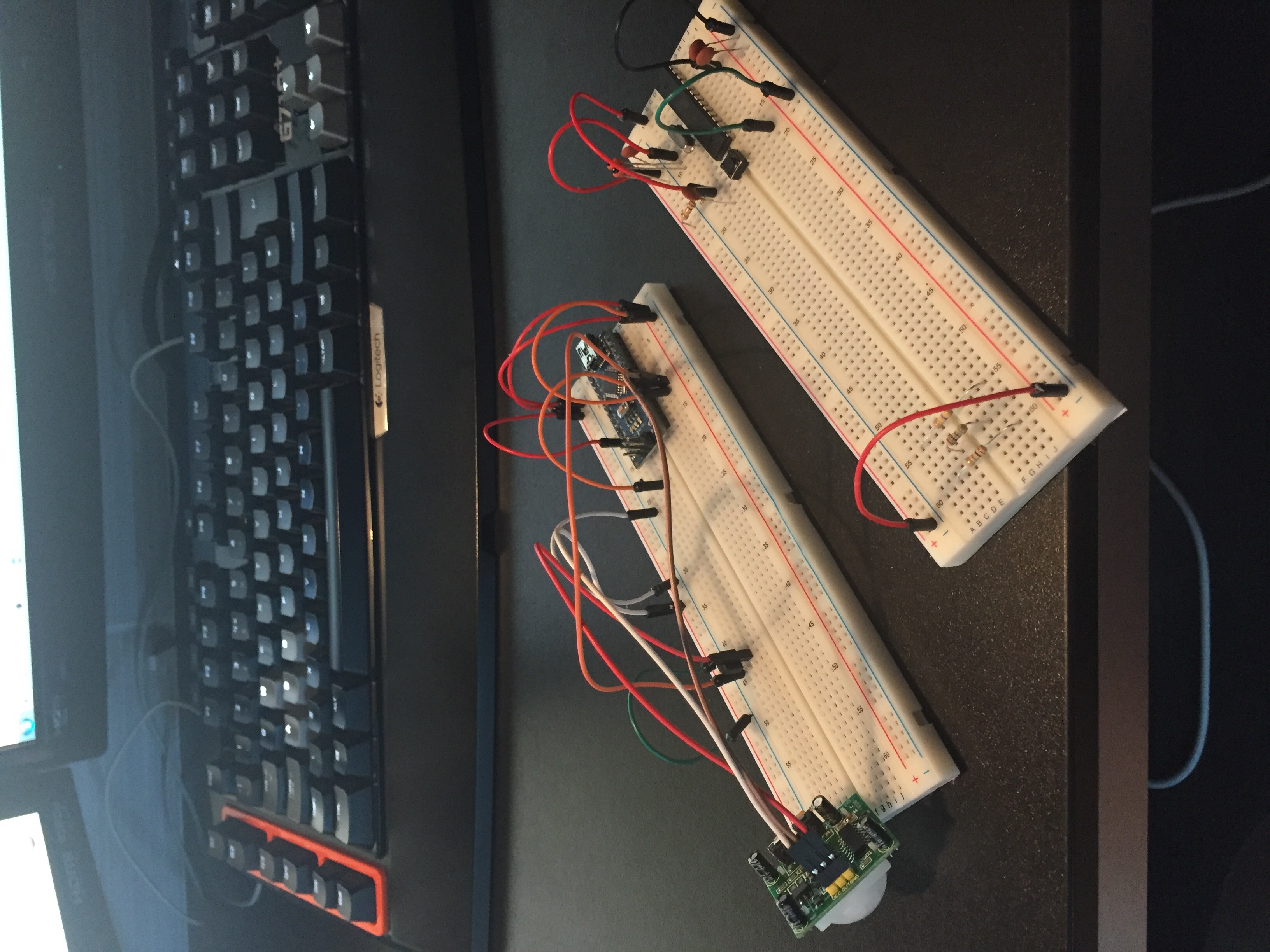
And the prototyping begins! Pretty much all of the breadboard versions of parts have arrived and i will be prototyping each circuit individually then wrapping it all together. A few mods need to be done to the light sensor to make it breadboard friendly but its doable!
Hello! It looks like you're interested in this conversation, but you don't have an account yet.
Getting fed up of having to scroll through the same posts each visit? When you register for an account, you'll always come back to exactly where you were before, and choose to be notified of new replies (either via email, or push notification). You'll also be able to save bookmarks and upvote posts to show your appreciation to other community members.
With your input, this post could be even better 💗
Register Login