Might have bricked 60 WS2811 RGB leds
-
@mfalkvidd You are using a 12V strip? If the supply voltage has not been above the rating chances are that the strip can still (partly) function. Have you read the überguide?
-
I was already using a capacitor between +12V and GND (I'm using 300uF and the überguide recommends 1000uF though)
I already had a resistor between the Arduino data pin and Din on the led strip.
can't seem to find anything else useful.I measured the voltage on Din on the first section. It is 1.3-1.7V depending on the brightness level. When measuring Dout on the first section, I get no voltage. So the data signal is not forwarded to the next section.
I am able to faintly light up the leds in the sections when using the diode tester mode on my cheap multimeter. From this my guess is that the logic chips are busted but the leds are still intact. Controlling them without the logic chips is a mess though.
@mfalkvidd I am a little confused... the WS2811 chip is a logic chip that does pass a digital code signal not PWM.. or am I missing the point here..:confused:
-
@mfalkvidd I am a little confused... the WS2811 chip is a logic chip that does pass a digital code signal not PWM.. or am I missing the point here..:confused:
@AWI are you referring to "I have added a PWM-driven led to the same Arduino"?
If so, this has nothing to do with the led strip. It is only used to show that the Arduino updates the brightness when I turn the potentiometer (since I'm no longer able to see the led strip). It uses a different output pin. -
I realized you might refer to my way of measuring the data signal. Just measuring the DC voltage is a crude way of measuring the signal, but that Dout of the first section has 0V all the time probably means that the signal is not getting through.
-
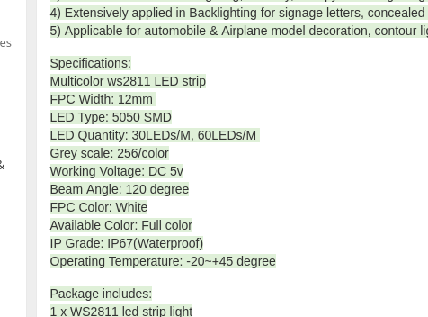
Are you absolutely sure that the LED strip is 12V? ws2811 chips are 5V only.. If you need higher supply voltage on the LED's you need to add FET's / Transistors to the ws2811.
If you read the specifications on the link, that you provided in the first post, then it also says 5V
-
I am pretty sure but one can never be really sure when buying electronics from China :). I ran the strips at 12V för 10+ minutes before I decided to switch the Arduino power from 5V through the usb connector to 12V on the raw pin. I doubt 5V leds would survive 10+ minutes on 12V.
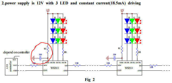
Also, the datasheet says 12V on page 5, application circuit 2.
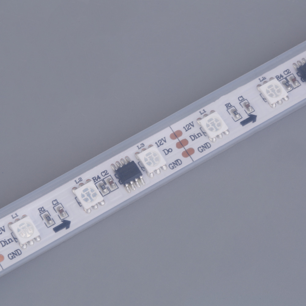 the text on the strip also says 12V
 -
I am pretty sure but one can never be really sure when buying electronics from China :). I ran the strips at 12V för 10+ minutes before I decided to switch the Arduino power from 5V through the usb connector to 12V on the raw pin. I doubt 5V leds would survive 10+ minutes on 12V.
Also, the datasheet says 12V on page 5, application circuit 2.
the text on the strip also says 12V@mfalkvidd 12V on the a WS2811 is normal the Led's are connected in series. The chip cannot handle 12V itself but has a 'stabilivolt' feature which lets you run the chip upto 24V if you put a resistor in series.
The data input (DIN) however is not very tolerant but is not connected to the output internally (some signal reshaping circuitry and logic in between). I would think that a peak voltage on the input would not be able to burn the whole chain.
Back to the resque: Do you have another proven setup where can connect the strip after removing the first 2 to 3 WS2811 (3 Led) segments from the strip?
-
@mfalkvidd 12V on the a WS2811 is normal the Led's are connected in series. The chip cannot handle 12V itself but has a 'stabilivolt' feature which lets you run the chip upto 24V if you put a resistor in series.
The data input (DIN) however is not very tolerant but is not connected to the output internally (some signal reshaping circuitry and logic in between). I would think that a peak voltage on the input would not be able to burn the whole chain.
Back to the resque: Do you have another proven setup where can connect the strip after removing the first 2 to 3 WS2811 (3 Led) segments from the strip?
@AWI said:
if you put a resistor in series.
by "you", do you mean me, mfalkvidd? Or the designer of the rgb strip? I think the rgb strip already has the necessary components built-in (especially since I got it working before frying the Arduino), but it could also be that the first Arduino happened to deliver a signal that got the strip working.
I cut off the last section of the strip and connected only that section to the Arduino. Nothing happens. So my guess is that the ICs of the entire strip are broken.
-
@AWI said:
if you put a resistor in series.
by "you", do you mean me, mfalkvidd? Or the designer of the rgb strip? I think the rgb strip already has the necessary components built-in (especially since I got it working before frying the Arduino), but it could also be that the first Arduino happened to deliver a signal that got the strip working.
I cut off the last section of the strip and connected only that section to the Arduino. Nothing happens. So my guess is that the ICs of the entire strip are broken.
@mfalkvidd you != @mfalkvidd (the resistor should be in the strip) ;-) I'll guess you are right that they died :cry: Destructive testing is a pain...
-
I fried up a ProMini when I provided 12V. Even though the specs says that it can handle 12V. Luckily I can stell power the Arduino through the FDTI power supply.
I still feed the arduino from the 12V power adaptor, that came with the LED strip. I'm doing it in two steps from 12V to 8V and from 8V to 3.3V. The LD33V can handle 12V but it get's really hot even with heat sink. By stepping down in two Phases both regulators get warm but not hot. After running this setup for a couple of weeks, I would dare to put that in a wall mount.
The schematics can be found at https://www.openhardware.io/view/50/Gesture-controlled-MySensors-Floor-lamp
-
Perhaps when the arduino died , the full 12v was put down the data pin to your led strip.... subsequently killing all ws2811 chips....
🤔What voltage do you see on the data pin on the arduino now if you connect it back to the 12v raw??
As you said, good thing these are cheap....
-
Perhaps when the arduino died , the full 12v was put down the data pin to your led strip.... subsequently killing all ws2811 chips....
🤔What voltage do you see on the data pin on the arduino now if you connect it back to the 12v raw??
As you said, good thing these are cheap....
Hello! It looks like you're interested in this conversation, but you don't have an account yet.
Getting fed up of having to scroll through the same posts each visit? When you register for an account, you'll always come back to exactly where you were before, and choose to be notified of new replies (either via email, or push notification). You'll also be able to save bookmarks and upvote posts to show your appreciation to other community members.
With your input, this post could be even better 💗
Register Login