Problems with first sensors
-
This is the code for my serial gateway to domoticz (arduino nano, NRF24L01+PA+ANTENNA) I am actually using...
 * The MySensors Arduino library handles the wireless radio link and protocol
 * between your home built sensors/actuators and HA controller of choice.
 * The sensors forms a self healing radio network with optional repeaters. Each
 * repeater and gateway builds a routing tables in EEPROM which keeps track of the
 * network topology allowing messages to be routed to nodes.
 *
 * Created by Henrik Ekblad <henrik.ekblad@mysensors.org>
 * Copyright (C) 2013-2015 Sensnology AB
 * Full contributor list: https://github.com/mysensors/Arduino/graphs/contributors
 *
 * Documentation: http://www.mysensors.org
 * Support Forum: http://forum.mysensors.org
 *
 * This program is free software; you can redistribute it and/or
 * modify it under the terms of the GNU General Public License
 * version 2 as published by the Free Software Foundation.
 *
 *******************************
 *
 * DESCRIPTION
 * The ArduinoGateway prints data received from sensors on the serial link.
 * The gateway accepts input on seral which will be sent out on radio network.
 *
 * The GW code is designed for Arduino Nano 328p / 16MHz
 *
 * Wire connections (OPTIONAL):
 * - Inclusion button should be connected between digital pin 3 and GND
 * - RX/TX/ERR leds need to be connected between +5V (anode) and digital pin 6/5/4 with resistor 270-330R in a series
 *
 * LEDs (OPTIONAL):
 * - To use the feature, uncomment MY_LEDS_BLINKING_FEATURE in MyConfig.h
 * - RX (green) - blink fast on radio message recieved. In inclusion mode will blink fast only on presentation recieved
 * - TX (yellow) - blink fast on radio message transmitted. In inclusion mode will blink slowly
 * - ERR (red) - fast blink on error during transmission error or recieve crc error
 *
 */

// Enable debug prints to serial monitor
#define MY_DEBUG


// Enable and select radio type attached
#define MY_RADIO_NRF24
//#define MY_RADIO_RFM69

// Set LOW transmit power level as default, if you have an amplified NRF-module and
// power your radio separately with a good regulator you can turn up PA level.
#define MY_RF24_PA_LEVEL RF24_PA_LOW

// Enable serial gateway
#define MY_GATEWAY_SERIAL

// Define a lower baud rate for Arduino's running on 8 MHz (Arduino Pro Mini 3.3V & SenseBender)
#if F_CPU == 8000000L
#define MY_BAUD_RATE 115200
#endif

// Flash leds on rx/tx/err
#define MY_LEDS_BLINKING_FEATURE
// Set blinking period
#define MY_DEFAULT_LED_BLINK_PERIOD 300

// Inverses the behavior of leds
//#define MY_WITH_LEDS_BLINKING_INVERSE

// Enable inclusion mode
#define MY_INCLUSION_MODE_FEATURE
// Enable Inclusion mode button on gateway
#define MY_INCLUSION_BUTTON_FEATURE

// Inverses behavior of inclusion button (if using external pullup)
//#define MY_INCLUSION_BUTTON_EXTERNAL_PULLUP

// Set inclusion mode duration (in seconds)
#define MY_INCLUSION_MODE_DURATION 60
// Digital pin used for inclusion mode button
#define MY_INCLUSION_MODE_BUTTON_PIN  3

// Uncomment to override default HW configurations
//#define MY_DEFAULT_ERR_LED_PIN 4  // Error led pin
//#define MY_DEFAULT_RX_LED_PIN  6  // Receive led pin
//#define MY_DEFAULT_TX_LED_PIN  5  // the PCB, on board LED

#include <SPI.h>
#include <MySensors.h>

void setup() {
  // Setup locally attached sensors
}

void presentation() {
 // Present locally attached sensors
}

void loop() {
  // Send locally attached sensor data here
}
And this sketch is for the motion sensor (arduino nano, HC-SR501 and NRF24L01+PA+ANTENNA)...
 * The MySensors Arduino library handles the wireless radio link and protocol
 * between your home built sensors/actuators and HA controller of choice.
 * The sensors forms a self healing radio network with optional repeaters. Each
 * repeater and gateway builds a routing tables in EEPROM which keeps track of the
 * network topology allowing messages to be routed to nodes.
 *
 * Created by Henrik Ekblad <henrik.ekblad@mysensors.org>
 * Copyright (C) 2013-2015 Sensnology AB
 * Full contributor list: https://github.com/mysensors/Arduino/graphs/contributors
 *
 * Documentation: http://www.mysensors.org
 * Support Forum: http://forum.mysensors.org
 *
 * This program is free software; you can redistribute it and/or
 * modify it under the terms of the GNU General Public License
 * version 2 as published by the Free Software Foundation.
 *
 *******************************
 *
 * REVISION HISTORY
 * Version 1.0 - Henrik Ekblad
 *
 * DESCRIPTION
 * Motion Sensor example using HC-SR501
 * http://www.mysensors.org/build/motion
 *
 */

// Enable debug prints
// #define MY_DEBUG

// Enable and select radio type attached
#define MY_RADIO_NRF24
//#define MY_RADIO_RFM69

#include <SPI.h>
#include <MySensors.h>

unsigned long SLEEP_TIME = 120000; // Sleep time between reports (in milliseconds)
#define DIGITAL_INPUT_SENSOR 3   // The digital input you attached your motion sensor.  (Only 2 and 3 generates interrupt!)
#define CHILD_ID 1   // Id of the sensor child

// Initialize motion message
MyMessage msg(CHILD_ID, V_TRIPPED);

void setup()
{
  pinMode(DIGITAL_INPUT_SENSOR, INPUT);      // sets the motion sensor digital pin as input
}

void presentation()  {
  // Send the sketch version information to the gateway and Controller
  sendSketchInfo("Motion Sensor", "1.0");

  // Register all sensors to gw (they will be created as child devices)
  present(CHILD_ID, S_MOTION);
}

void loop()
{
  // Read digital motion value
  boolean tripped = digitalRead(DIGITAL_INPUT_SENSOR) == HIGH;

  Serial.println(tripped);
  send(msg.set(tripped?"1":"0"));  // Send tripped value to gw

  // Sleep until interrupt comes in on motion sensor. Send update every two minute.
  sleep(digitalPinToInterrupt(DIGITAL_INPUT_SENSOR), CHANGE, SLEEP_TIME);
}
Domoticz still recognizes the motion sensor as "unknown" and S_ARDUINO_REPEATER.
And, the debug seriell monitor tells me:
Starting sensor (RNNNA-, 2.0.0)
TSM:INIT
TSM:RADIO:OK
TSM:FPAR
TSP:MSG:SEND 255-255-255-255 s=255,c=3,t=7,pt=0,l=0,sg=0,ft=0,st=bc:
TSM:FPAR
TSP:MSG:SEND 255-255-255-255 s=255,c=3,t=7,pt=0,l=0,sg=0,ft=0,st=bc:
TSM:FPAR
TSP:MSG:SEND 255-255-255-255 s=255,c=3,t=7,pt=0,l=0,sg=0,ft=0,st=bc:
TSM:FPAR
TSP:MSG:SEND 255-255-255-255 s=255,c=3,t=7,pt=0,l=0,sg=0,ft=0,st=bc:
!TSM:FPAR:FAIL
!TSM:FAILURE
TSM:PDT
Hope, someone can help - it is very frustrating.
-
Okay, could you please tell me how to do that.
At the moment I do not know where to find it.@blebbens connect the gateway to your computer usb port and look at the serial to see the debug log.
In addition where does domoticz show the "unknown" sensor? In the hardware log there is always one with id 255 for the node.
From you log I read a lot of "failed" messages. This indicates transmission errors which could result from your amplified radio's. These a more error prone than the non amplified ones. For testing you better use the non amplified.
-
I don't know about domoticz but perhaps you can get the logs. Or use MYSController.
Otherwise, when you need it, you can debug gw and node on your computer. Just connect both devices to your computer. Then of course this is not connected to domoticz but for debugging i often do this, it's useful.
So:
- connect gw+node to your computer
- then use Serial monitor from arduino if you want, to monitor one device. choose right baudrate and comport of course
- and for other device, use another serial monitor like putty etc..
or a sniffer if you really want to keep it connected to your controller. But for noobs, i would advice to simply use two serial monitor when you need to debug, easier..
-
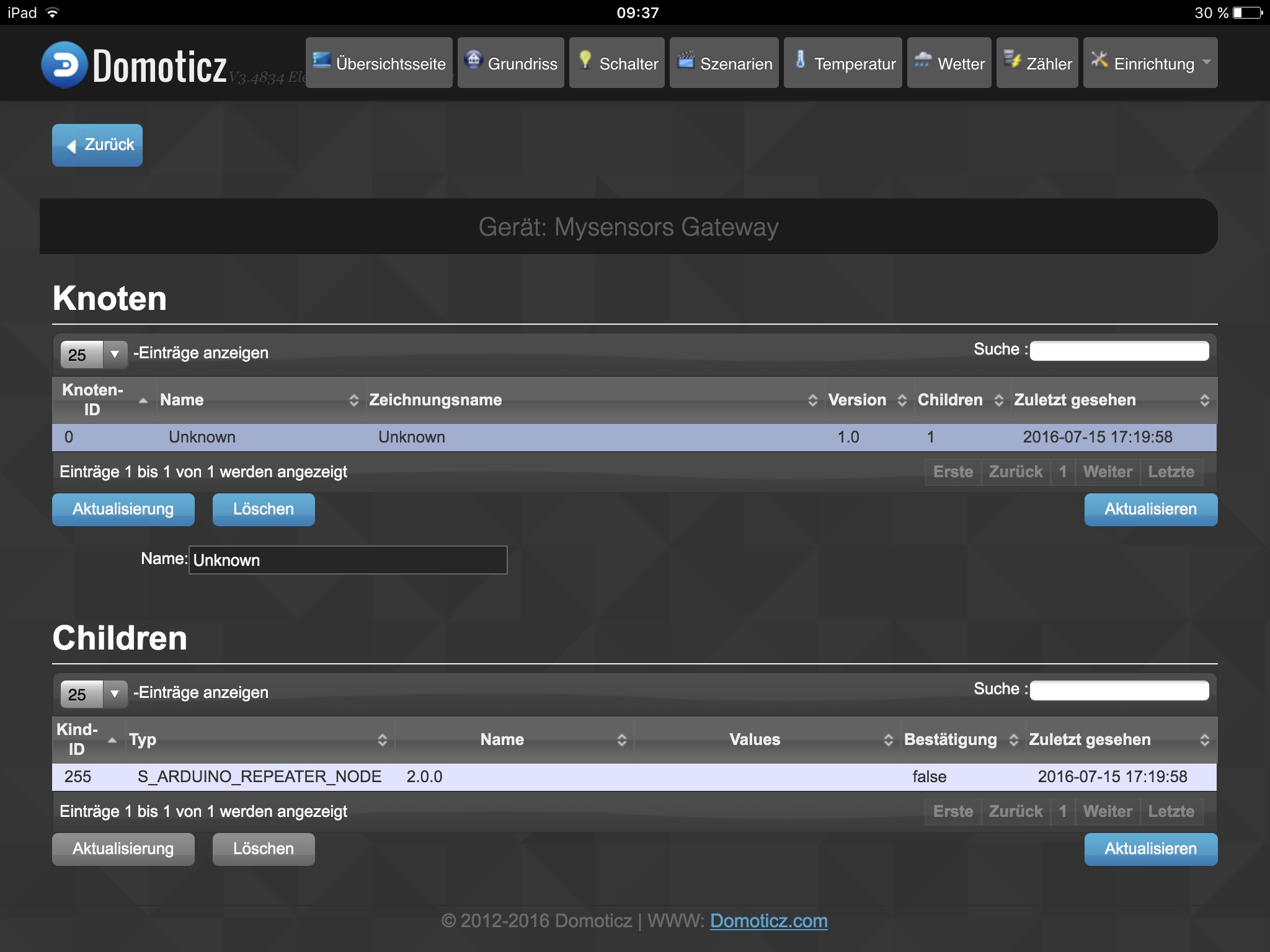
This is what domoticz looks like...
Connecting the serial gateway to my computer means, I can not connect it to domoticz ?
For debugging I have to enable #define MY_DEBUG ?
Or, is there a way to read the log file on the gateway ?@blebbens your domoticz screen looks fine. No errors but also no sensors reported. Only the node is known.
As @scalz mentioned, just connect the node and gateway to your computer watch what happens on the serial monitor (arduino idea or whatever you are using) the node does not have to be connected to domoticz for initial debugging. -
Okay, I have...
The motion sensor connected to the Arduino IDE. The output of the serial monitor (at this time the gateway was connected to the controller):
Starting sensor (RNNNA-, 2.0.0)
TSM:INIT
TSM:RADIO:OK
TSM:FPAR
TSP:MSG:SEND 255-255-255-255 s=255,c=3,t=7,pt=0,l=0,sg=0,ft=0,st=bc:
TSM:FPAR
TSP:MSG:SEND 255-255-255-255 s=255,c=3,t=7,pt=0,l=0,sg=0,ft=0,st=bc:
TSM:FPAR
TSP:MSG:SEND 255-255-255-255 s=255,c=3,t=7,pt=0,l=0,sg=0,ft=0,st=bc:
TSM:FPAR
TSP:MSG:SEND 255-255-255-255 s=255,c=3,t=7,pt=0,l=0,sg=0,ft=0,st=bc:
!TSM:FPAR:FAIL
!TSM:FAILURE
TSM:PDT
TSM:INIT
TSM:RADIO:OK
TSM:FPAR
TSP:MSG:SEND 255-255-255-255 s=255,c=3,t=7,pt=0,l=0,sg=0,ft=0,st=bc:
TSM:FPAR
TSP:MSG:SEND 255-255-255-255 s=255,c=3,t=7,pt=0,l=0,sg=0,ft=0,st=bc:
TSM:FPAR
TSP:MSG:SEND 255-255-255-255 s=255,c=3,t=7,pt=0,l=0,sg=0,ft=0,st=bc:
TSM:FPAR
TSP:MSG:SEND 255-255-255-255 s=255,c=3,t=7,pt=0,l=0,sg=0,ft=0,st=bc:
An at this point I had the gateway connected to the arduino IDE (the motion sensor was not connected to the computer):
0;255;3;0;9;Starting gateway (RNNGA-, 2.0.0)
0;255;3;0;9;TSM:INIT
0;255;3;0;9;TSM:RADIO:OK
0;255;3;0;9;TSM:GW MODE
0;255;3;0;9;TSM:READY
0;255;3;0;14;Gateway startup complete.
0;255;0;0;18;2.0.0
0;255;3;0;9;No registration required
0;255;3;0;9;Init complete, id=0, parent=0, distance=0, registration=1
0;255;3;0;9;TSP:SANCHK:OK
0;255;3;0;9;TSP:SANCHK:OK
0;255;3;0;9;TSP:SANCHK:OK
0;255;3;0;9;TSP:SANCHK:OK
0;255;3;0;9;TSP:SANCHK:OK
0;255;3;0;9;TSP:SANCHK:OK
0;255;3;0;9;TSP:SANCHK:OK
I never had both, gateway and sensor, connected to the monitor at the same time. I am afraid, I didn´t understand to use MYScontroller. Did not find the com-port settings etc. It always tries to connect to gateway 192.168.0.x, my network is not set up to this IP.
Does the output help ?
-
nope, output can't help as it's only one device..
I think you're talking about MYSController config when you say 192.168.0.x, isn't it? or i don't understand lol
To know your serialports in use:
- with Win for instance, go to something like Control Panel → Device Manager → COM & LPT ports
- connect your devices to usb, and disconnect one by one. So now you know which one use which port.
About MYSController: you will need to setup the serial port for GW.
- With GW connected to usb, click Settings button and then click Gateway tab.
- Check Serial GW and choose port&bauds.
- Now, still in MYSController, you can click Connect button. There are tabs in MYSController for different debug levels. Look a bit at features.
- It should connect, if it does not, un/replug your gw, and reclick Connect.
Then you'll have the logs for your GW if it is enabled in sketch of course.
As said above, if you would like, you could use another software (serial monitor) in place of MYSController. but not required here.Now, for the other device (node), you can monitor it in Arduino software by setting well port&bauds. you know it now ;)
Could you try in this order, please :
- plug GW only. And connect with MYSController
- then plug node, and open your Arduino Serial monitor.
does it work? if no, logs, thx ;)
-
Okay, done it... both connected, gw on MYScontroller, motion sensor monitored using IDE...
Sensor output:
TSM:INIT
TSM:RADIO:OK
TSM:FPAR
TSP:MSG:SEND 255-255-255-255 s=255,c=3,t=7,pt=0,l=0,sg=0,ft=0,st=bc:
TSM:FPAR
TSP:MSG:SEND 255-255-255-255 s=255,c=3,t=7,pt=0,l=0,sg=0,ft=0,st=bc:
TSM:FPAR
TSP:MSG:SEND 255-255-255-255 s=255,c=3,t=7,pt=0,l=0,sg=0,ft=0,st=bc:
TSM:FPAR
TSP:MSG:SEND 255-255-255-255 s=255,c=3,t=7,pt=0,l=0,sg=0,ft=0,st=bc:
!TSM:FPAR:FAIL
!TSM:FAILURE
TSM:PDT
And gateway output:
MYScontroller debug:
16.07.2016 19:43:42	INFO	Flushing FIFO
16.07.2016 19:43:42	INFO	Connected to COM7
16.07.2016 19:43:44	RX	0;255;3;0;9;Starting gateway (RNNGA-, 2.0.0)
16.07.2016 19:43:44	CHILD	New child discovered, node id=0, child id=internal
16.07.2016 19:43:44	RX	0;255;3;0;9;TSM:INIT
16.07.2016 19:43:44	RX	0;255;3;0;9;TSM:RADIO:OK
16.07.2016 19:43:44	RX	0;255;3;0;9;TSM:GW MODE
16.07.2016 19:43:44	RX	0;255;3;0;9;TSM:READY
16.07.2016 19:43:44	RX	0;255;3;0;14;Gateway startup complete.
16.07.2016 19:43:44	RX	0;255;0;0;18;2.0.0
16.07.2016 19:43:44	DEBUG	Update child id=255, type=S_ARDUINO_REPEATER_NODE
16.07.2016 19:43:44	RX	0;255;3;0;9;No registration required
16.07.2016 19:43:44	RX	0;255;3;0;9;Init complete, id=0, parent=0, distance=0, registration=1
16.07.2016 19:44:44	RX	0;255;3;0;9;TSP:SANCHK:OK
16.07.2016 19:45:44	RX	0;255;3;0;9;TSP:SANCHK:OK
MySensors debug:
8 16.07.2016 19:43:44 TX -1 -1 -1 -1 NA (-1) N/A NA (-1) -1 requiredNodes debug: this message was shown before I connected the sensor to power
7 16.07.2016 19:43:44 0 - Gateway S_ARDUINO_REPEATER_NODE S_ARDUINO_REPEATER_NODE 2.0.0And messages tab:
6	16.07.2016 19:43:44	RX	0 - Gateway	INTERNAL	C_INTERNAL	NO	I_GATEWAY_READY	Gateway startup complete.
7	16.07.2016 19:43:44	RX	0 - Gateway	INTERNAL	C_PRESENTATION	NO	S_ARDUINO_REPEATER_NODE	2.0.0
Okay, hope, this helps now.
That´s strange, because there is no repeater... just a motion sensor sketch.
-
No one ? It is so frustrating...
Read some more threads like this (https://forum.mysensors.org/topic/4280/simple-serial-gateway-and-sensor-does-not-work)... seems to be a common problem of MySensors 2.0 ?
-
-
No one ? It is so frustrating...
Read some more threads like this (https://forum.mysensors.org/topic/4280/simple-serial-gateway-and-sensor-does-not-work)... seems to be a common problem of MySensors 2.0 ?
@blebbens Your logs look ok, but your radios don't seem to talk to each other - this could possibly hint to radio interference or HW issues. Try:
(1) reduce PA power by setting:#define MY_RF24_PA_LEVEL RF24_PA_LOWand recompile and reflash GW and node sketch.
(2) move node and GW further away from each other
(3) Switch off WiFi APPlease report back on any of these solutions with log from GW and node.
Thanks.
-
Now I defined MY_RF24_PA_LEVEL RF24_PA_LOW in both, gateway and sensor.
Before I have done this, I compiled and uploaded the ClearEpromConfig.The logs... gateway:
17.07.2016 15:52:22	STARTUP	Initialize message logging
17.07.2016 15:52:22	STARTUP	1.0.0 (build 3314)
17.07.2016 15:52:22	STARTUP	FPC 3.0.0 / Lazarus 1.6
17.07.2016 15:52:22	STARTUP	still under development :) tekka 2016
17.07.2016 15:52:22	STARTUP	Load INI file...
17.07.2016 15:52:22	STARTUP	INI version 1.0.0 (build 3314)
17.07.2016 15:52:23	INFO	*** Logging START ***
17.07.2016 15:52:23	VERSION	1.0.0 (build 3314)
17.07.2016 15:52:23	INFO	Logging=TRUE
17.07.2016 15:52:23	INFO	AutoID=TRUE
17.07.2016 15:52:23	INFO	AutoFW=TRUE
17.07.2016 15:52:23	STARTUP	INI file loaded
17.07.2016 15:52:23	STARTUP	Loading FW repository...
17.07.2016 15:52:23	REPO	FW "Blink" loaded. t=10, v=1, blocks=80, crc=0x46D4
17.07.2016 15:52:23	REPO	FW "TimeReporter" loaded. t=20, v=1, blocks=736, crc=0xE923
17.07.2016 15:52:23	REPO	FW repository loaded. Items=2
17.07.2016 15:52:23	STARTUP	Initialize message types
17.07.2016 15:52:23	NODE	New node discovered, node id=0
17.07.2016 15:52:23	NODE	New node discovered, node id=255
17.07.2016 15:52:23	INFO	read MySensors.xml
17.07.2016 15:52:23	INFO	Application: MYSController
17.07.2016 15:52:23	INFO	Node id=0 skipped
17.07.2016 15:52:23	INFO	Node id=255 skipped
17.07.2016 15:52:30	UPDATE	current=1.0.0.3314 remote=1.0.0.3314
17.07.2016 15:52:32	INFO	Flushing FIFO
17.07.2016 15:52:32	INFO	Connected to COM9
17.07.2016 15:52:34	RX	0;255;3;0;9;Starting gateway (RNNGA-, 2.0.0)
17.07.2016 15:52:34	CHILD	New child discovered, node id=0, child id=internal
17.07.2016 15:52:34	RX	0;255;3;0;9;TSM:INIT
17.07.2016 15:52:34	RX	0;255;3;0;9;TSM:RADIO:OK
17.07.2016 15:52:34	RX	0;255;3;0;9;TSM:GW MODE
17.07.2016 15:52:34	RX	0;255;3;0;9;TSM:READY
17.07.2016 15:52:34	RX	0;255;3;0;14;Gateway startup complete.
17.07.2016 15:52:34	RX	0;255;0;0;18;2.0.0
17.07.2016 15:52:34	DEBUG	Update child id=255, type=S_ARDUINO_REPEATER_NODE
17.07.2016 15:52:34	RX	0;255;3;0;9;No registration required
17.07.2016 15:52:34	RX	0;255;3;0;9;Init complete, id=0, parent=0, distance=0, registration=1
6 17.07.2016 15:52:34 RX 0 - Gateway INTERNAL C_INTERNAL NO I_GATEWAY_READY Gateway startup complete. 7 17.07.2016 15:52:34 RX 0 - Gateway INTERNAL C_PRESENTATION NO S_ARDUINO_REPEATER_NODE 2.0.0And, the sensor...
TSM:INIT
TSM:RADIO:OK
TSM:FPAR
TSP:MSG:SEND 255-255-255-255 s=255,c=3,t=7,pt=0,l=0,sg=0,ft=0,st=bc:
TSM:FPAR
TSP:MSG:SEND 255-255-255-255 s=255,c=3,t=7,pt=0,l=0,sg=0,ft=0,st=bc:
TSM:FPAR
TSP:MSG:SEND 255-255-255-255 s=255,c=3,t=7,pt=0,l=0,sg=0,ft=0,st=bc:
TSM:FPAR
TSP:MSG:SEND 255-255-255-255 s=255,c=3,t=7,pt=0,l=0,sg=0,ft=0,st=bc:
!TSM:FPAR:FAIL
!TSM:FAILURE
TSM:PDT
They now are far away from each other...
I think, all cables are connected to the right position.
EDIT:
Found a MQ-135 air quality sensor. Uploaded the mysensor example sketch. But, the same error output in serial monitor.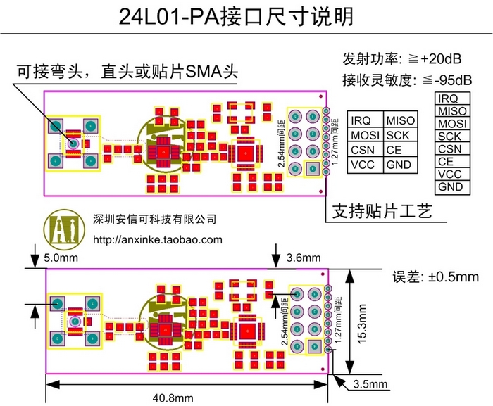
Please take a look at this picture of my NRF24L01 amplified. Perhaps, it is wrong wired ? On my NRF24 there is no mark for GND, so I took this picture.
But, isn´t my gateway (wired the same) working very well ? Is there a way to find out, if the wiring is wrong ? Would the gateway work like you can see in the log ?
Or another idea: I changed the gateway´s sketch to a baud rate of 115200. The sensor´s sketches don´t contain this information. Do I need to set their baud rate to 115200, too ?
-
Now I defined MY_RF24_PA_LEVEL RF24_PA_LOW in both, gateway and sensor.
Before I have done this, I compiled and uploaded the ClearEpromConfig.The logs... gateway:
17.07.2016 15:52:22	STARTUP	Initialize message logging
17.07.2016 15:52:22	STARTUP	1.0.0 (build 3314)
17.07.2016 15:52:22	STARTUP	FPC 3.0.0 / Lazarus 1.6
17.07.2016 15:52:22	STARTUP	still under development :) tekka 2016
17.07.2016 15:52:22	STARTUP	Load INI file...
17.07.2016 15:52:22	STARTUP	INI version 1.0.0 (build 3314)
17.07.2016 15:52:23	INFO	*** Logging START ***
17.07.2016 15:52:23	VERSION	1.0.0 (build 3314)
17.07.2016 15:52:23	INFO	Logging=TRUE
17.07.2016 15:52:23	INFO	AutoID=TRUE
17.07.2016 15:52:23	INFO	AutoFW=TRUE
17.07.2016 15:52:23	STARTUP	INI file loaded
17.07.2016 15:52:23	STARTUP	Loading FW repository...
17.07.2016 15:52:23	REPO	FW "Blink" loaded. t=10, v=1, blocks=80, crc=0x46D4
17.07.2016 15:52:23	REPO	FW "TimeReporter" loaded. t=20, v=1, blocks=736, crc=0xE923
17.07.2016 15:52:23	REPO	FW repository loaded. Items=2
17.07.2016 15:52:23	STARTUP	Initialize message types
17.07.2016 15:52:23	NODE	New node discovered, node id=0
17.07.2016 15:52:23	NODE	New node discovered, node id=255
17.07.2016 15:52:23	INFO	read MySensors.xml
17.07.2016 15:52:23	INFO	Application: MYSController
17.07.2016 15:52:23	INFO	Node id=0 skipped
17.07.2016 15:52:23	INFO	Node id=255 skipped
17.07.2016 15:52:30	UPDATE	current=1.0.0.3314 remote=1.0.0.3314
17.07.2016 15:52:32	INFO	Flushing FIFO
17.07.2016 15:52:32	INFO	Connected to COM9
17.07.2016 15:52:34	RX	0;255;3;0;9;Starting gateway (RNNGA-, 2.0.0)
17.07.2016 15:52:34	CHILD	New child discovered, node id=0, child id=internal
17.07.2016 15:52:34	RX	0;255;3;0;9;TSM:INIT
17.07.2016 15:52:34	RX	0;255;3;0;9;TSM:RADIO:OK
17.07.2016 15:52:34	RX	0;255;3;0;9;TSM:GW MODE
17.07.2016 15:52:34	RX	0;255;3;0;9;TSM:READY
17.07.2016 15:52:34	RX	0;255;3;0;14;Gateway startup complete.
17.07.2016 15:52:34	RX	0;255;0;0;18;2.0.0
17.07.2016 15:52:34	DEBUG	Update child id=255, type=S_ARDUINO_REPEATER_NODE
17.07.2016 15:52:34	RX	0;255;3;0;9;No registration required
17.07.2016 15:52:34	RX	0;255;3;0;9;Init complete, id=0, parent=0, distance=0, registration=1
6 17.07.2016 15:52:34 RX 0 - Gateway INTERNAL C_INTERNAL NO I_GATEWAY_READY Gateway startup complete. 7 17.07.2016 15:52:34 RX 0 - Gateway INTERNAL C_PRESENTATION NO S_ARDUINO_REPEATER_NODE 2.0.0And, the sensor...
TSM:INIT
TSM:RADIO:OK
TSM:FPAR
TSP:MSG:SEND 255-255-255-255 s=255,c=3,t=7,pt=0,l=0,sg=0,ft=0,st=bc:
TSM:FPAR
TSP:MSG:SEND 255-255-255-255 s=255,c=3,t=7,pt=0,l=0,sg=0,ft=0,st=bc:
TSM:FPAR
TSP:MSG:SEND 255-255-255-255 s=255,c=3,t=7,pt=0,l=0,sg=0,ft=0,st=bc:
TSM:FPAR
TSP:MSG:SEND 255-255-255-255 s=255,c=3,t=7,pt=0,l=0,sg=0,ft=0,st=bc:
!TSM:FPAR:FAIL
!TSM:FAILURE
TSM:PDT
They now are far away from each other...
I think, all cables are connected to the right position.
EDIT:
Found a MQ-135 air quality sensor. Uploaded the mysensor example sketch. But, the same error output in serial monitor.Please take a look at this picture of my NRF24L01 amplified. Perhaps, it is wrong wired ? On my NRF24 there is no mark for GND, so I took this picture.
But, isn´t my gateway (wired the same) working very well ? Is there a way to find out, if the wiring is wrong ? Would the gateway work like you can see in the log ?
Or another idea: I changed the gateway´s sketch to a baud rate of 115200. The sensor´s sketches don´t contain this information. Do I need to set their baud rate to 115200, too ?
-
@blebbens
could you show a link where you bought radio modules you're using please. I think @tekka may have found the problem :)For people who are getting same messages "FPAR FAIL", I think you may fall into the old case "st:fail", hardware related like using capa for radio, tekka advices above etc... where radio does not work properly and there is no ACK back so the comm is not validated. Then, after multiple retries, it fails.
I can confirm this at least for static nodes. On my side, the latest v2.0 from dev branch works ok for me. as expected ;) Config tested for the moment is serial gw with exotic mcu atsam (I mean compared to classic gw). And the node is a multisensors. Radio is RFM69.
-
Flashed ClearEpromConfig...
Added to the sketches...
#define MY_RF24_PA_LEVEL RF24_PA_LOW
#define MY_RF24_DATARATE RF24_1MBPSThink, this overrides MyConfig.h ?
What a pity... just the same output... recognized as "unknown" S_ARDUINO_REPEATER_NODE.
But, the delivered NRFs have no marked GND.
Oh, any ideas left ? Delivery of standard NRFs take 30-40 days.
Extract of MyConfig.h:
/** * @def MY_RF24_SPI_MAX_SPEED * @brief MY_RF24_SPI_MAX_SPEED to overrule default nRF24L01+ SPI speed. */ //#define MY_RF24_SPI_MAX_SPEED 4000000 /** * @def MY_RF24_CE_PIN * @brief Default RF24 chip enable pin setting. Override in sketch if needed. */ #ifndef MY_RF24_CE_PIN #if defined(ARDUINO_ARCH_ESP8266) #define MY_RF24_CE_PIN 4 #elif defined(ARDUINO_ARCH_SAMD) #define MY_RF24_CE_PIN 27 #else #define MY_RF24_CE_PIN 9 #endif #endif /** * @def MY_RF24_CS_PIN * @brief Default RF24 chip select pin setting. Override in sketch if needed. */ #ifndef MY_RF24_CS_PIN #if defined(ARDUINO_ARCH_ESP8266) #define MY_RF24_CS_PIN 15 #elif defined(ARDUINO_ARCH_SAMD) #define MY_RF24_CS_PIN 3 #else #define MY_RF24_CS_PIN 10 #endif #endif /** * @def MY_RF24_PA_LEVEL * @brief Default RF24 PA level. Override in sketch if needed. */ #ifndef MY_RF24_PA_LEVEL #define MY_RF24_PA_LEVEL RF24_PA_LOW #endif /** * @def MY_RF24_CHANNEL * @brief RF channel for the sensor net, 0-125. * Frequence: 2400 Mhz - 2525 Mhz Channels: 126 * http://www.mysensors.org/radio/nRF24L01Plus.pdf * 0 => 2400 Mhz (RF24 channel 1) * 1 => 2401 Mhz (RF24 channel 2) * 76 => 2476 Mhz (RF24 channel 77) * 83 => 2483 Mhz (RF24 channel 84) * 124 => 2524 Mhz (RF24 channel 125) * 125 => 2525 Mhz (RF24 channel 126) * In some countries there might be limitations, in Germany for example only the range 2400,0 - 2483,5 Mhz is allowed * http://www.bundesnetzagentur.de/SharedDocs/Downloads/DE/Sachgebiete/Telekommunikation/Unternehmen_Institutionen/Frequenzen/Allgemeinzuteilungen/2013_10_WLAN_2,4GHz_pdf.pdf */ #ifndef MY_RF24_CHANNEL #define MY_RF24_CHANNEL 76 #endif /** * @def MY_RF24_DATARATE * @brief RF24 datarate (RF24_250KBPS for 250kbs, RF24_1MBPS for 1Mbps or RF24_2MBPS for 2Mbps). */ #ifndef MY_RF24_DATARATE #define MY_RF24_DATARATE RF24_250KBPS #endif -
Have you tried to use another sketch?
Just a random mysensors sketch to see if it that one also get presented as repeater node.
Maybe just take one with a button and make your own (if you dont have any) and see if the buttonpress gets transmitted. -
Have you tried to use another sketch?
Just a random mysensors sketch to see if it that one also get presented as repeater node.
Maybe just take one with a button and make your own (if you dont have any) and see if the buttonpress gets transmitted.@Tore-André-Rosander
Have tried out different sample-sketches from library, e.g. motion and air quality.It is... so... frustrating. There has to be a stupid mistake causing the sensors to report their availability as repeater node.
-
@Tore-André-Rosander
Have tried out different sample-sketches from library, e.g. motion and air quality.It is... so... frustrating. There has to be a stupid mistake causing the sensors to report their availability as repeater node.
@blebbens I totally understand your frustration but I'm afraid, your issue seems HW/radio-related. The logs look normal, also the repeater node message (which is actually emitted from the GW, see your domoticz screenshot and GW log). If you can get a different pair of nRF24L01+ (the P-version), I'd retry with those.
-
Is it just me or does it look like the repeater node is not the actual sensor node?
If you look at the logs " Gateway INTERNAL C_PRESENTATION NO S_ARDUINO_REPEATER_NODE 2.0.0" "New child discovered, node id=0, child id=internal" and "Update child id=255, type=S_ARDUINO_REPEATER_NODE"
How about try to define the node id manually?
And just to be sure the clear eeprom config sketch in the mySensors examples.
You can also try the RF24 library ping-pong examples to test your radios.
Hello! It looks like you're interested in this conversation, but you don't have an account yet.
Getting fed up of having to scroll through the same posts each visit? When you register for an account, you'll always come back to exactly where you were before, and choose to be notified of new replies (either via email, or push notification). You'll also be able to save bookmarks and upvote posts to show your appreciation to other community members.
With your input, this post could be even better 💗
Register Login