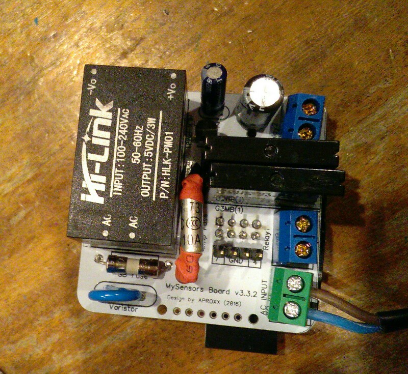
💬 AC-DC double solid state relay module
-
Aproxx you roxx. It works! Not sure what to do with it yet, but likely it will end up in a wall sometime soon on light duties. Thanks for sharing such a great design :-)
Hmm just pulled some switches, they are mostly SPDT jobbies on multiple switches, no idea how to hood this bad-boy up =( -
Hi everyone,
First I would like to thank the OP for sharing this great project :)
Then I would like to ask what would happen if the node cannot connect to the gateway on startup? It would still be possible to use the switch?
Thank you,
-
Hi everyone,
First I would like to thank the OP for sharing this great project :)
Then I would like to ask what would happen if the node cannot connect to the gateway on startup? It would still be possible to use the switch?
Thank you,
@Daniel-Oliveira said:
Then I would like to ask what would happen if the node cannot connect to the gateway on startup? It would still be possible to use the switch?
Hello, on startup if it cannot connect to gateway MySensors library will loop until it connects, so no. But once started as you have direct connection to the switch it will work even if the gateway fails.
-
@Daniel-Oliveira said:
Then I would like to ask what would happen if the node cannot connect to the gateway on startup? It would still be possible to use the switch?
Hello, on startup if it cannot connect to gateway MySensors library will loop until it connects, so no. But once started as you have direct connection to the switch it will work even if the gateway fails.
@Nca78 Thank you for the reply,
There is a way to overcame that? Like add a max retry of sorts? My concern is that if by some reason the gateway fails and the node reboots I will not be able use the switch.
Or does MySensors have another fail safe mechanism that I'm not aware?
-
No that I know.
But this situation is really unlikely, nodes are very stable usually (else you'll quickly see a problem). Basically you would need the gateway to fail, then a power outage to reboot your node. -
@okos if you have the device in Domoticz it means it could run, and send data to the gateway controller.
Did you change anything in hardware of software between the moment you added the node/sensor to Domoticz and the moment you tried to activate it ?
Are you sure your settings for the ACK are ok ? Maybe you are not sending one in the node but waiting from one in Domoticz ? Check the "Ack" column in Domoticz and if it's true try to change it to false.@Nca78 said:
@okos if you have the device in Domoticz it means it could run, and send data to the gateway controller.
Did you change anything in hardware of software between the moment you added the node/sensor to Domoticz and the moment you tried to activate it ?
Are you sure your settings for the ACK are ok ? Maybe you are not sending one in the node but waiting from one in Domoticz ? Check the "Ack" column in Domoticz and if it's true try to change it to false.Thanks for the answer :smiley: Nca78, but I do not know where to look for settings Ack.
Please help -
@Nca78 said:
@okos if you have the device in Domoticz it means it could run, and send data to the gateway controller.
Did you change anything in hardware of software between the moment you added the node/sensor to Domoticz and the moment you tried to activate it ?
Are you sure your settings for the ACK are ok ? Maybe you are not sending one in the node but waiting from one in Domoticz ? Check the "Ack" column in Domoticz and if it's true try to change it to false.Thanks for the answer :smiley: Nca78, but I do not know where to look for settings Ack.
Please help@okos go to Setup menu / Hardware, then click on the "Setup" button for your MySensors gateway.
In the top list select the node, and in the bottom you will see the sensors attached to this node, and a Ack column for each sensor. To edit the ack column just select item and you have the checkbox below the grid with update button. -
@okos go to Setup menu / Hardware, then click on the "Setup" button for your MySensors gateway.
In the top list select the node, and in the bottom you will see the sensors attached to this node, and a Ack column for each sensor. To edit the ack column just select item and you have the checkbox below the grid with update button. -
First board soldered and tested, it runs very well, thank you for the great work @aproxx !
Thank you @Konstantin-Kolesnichenko also for adapting the script to version 2.0.I just didn't dare to install the ds18b20, the tiny distance to the temp fuse pad gives me some nightmares :cold_sweat: so I prefer having no temperature sensor and put a piece of insulating tape on both sides.
This one will go in the ceiling, but for next board I will keep the vcc pin of the NRF24 and change a bit the code to use touch sensors behind a livolo glass plate. I need some top level WAF before I can go on with the MySensorization of all the appartment :D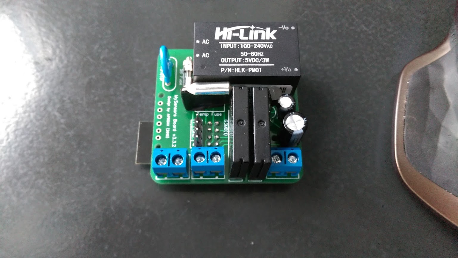 (like the others I will not show the back side and it's ugly pieces of insulating tape :D)
@okos did you fix your problem ? I see your deleted message.
-
First board soldered and tested, it runs very well, thank you for the great work @aproxx !
Thank you @Konstantin-Kolesnichenko also for adapting the script to version 2.0.I just didn't dare to install the ds18b20, the tiny distance to the temp fuse pad gives me some nightmares :cold_sweat: so I prefer having no temperature sensor and put a piece of insulating tape on both sides.
This one will go in the ceiling, but for next board I will keep the vcc pin of the NRF24 and change a bit the code to use touch sensors behind a livolo glass plate. I need some top level WAF before I can go on with the MySensorization of all the appartment :D (like the others I will not show the back side and it's ugly pieces of insulating tape :D)@okos did you fix your problem ? I see your deleted message.
@okos did you fix your problem ? I see your deleted message.
Now everything is ok.
Nrf changed, and changed the position of the gate (it is now above - on the fridge :))But I have another problem
I used the code from Konstantin Kolesnichenko (thanks), and even after the power is changing relay.Example:
on relay 1
off Relay 2turn off the power, and after power returning I
on relay 2
off Relay 1Why exchange ?
-
@okos did you fix your problem ? I see your deleted message.
Now everything is ok.
Nrf changed, and changed the position of the gate (it is now above - on the fridge :))But I have another problem
I used the code from Konstantin Kolesnichenko (thanks), and even after the power is changing relay.Example:
on relay 1
off Relay 2turn off the power, and after power returning I
on relay 2
off Relay 1Why exchange ?
@okos I will try to do more tests tomorrow to see if I have the same problem. I see no obvious mistake in the script that would generate this though. The only thing I see would be if you have linked your module with physical switches and they are in different position. As the script assumes that at startup the buttons are in "off" position (circuit opened).
I think we should have this code at the end of the setup() method to initialize the oldValue and oldValue2 variables.
// Set the initial values of oldValue/oldValue2 variables from status of physical switches debouncer.update(); debouncer2.update(); oldValue = debouncer.read(); oldValue2 = debouncer2.read(); -
@okos I confirm to you that without the change in my previous message, I had a similar problem (relay 1 always on and relay 2 always off at startup). After applying the change I don't have any problem on restart, it was just an initialization problem.
I'm making some small improvements to the sketch, I will test tomorrow and post it. -
Hello,
this is the updated code, the list of changes at the top of the script.
In short :- fixed initialization of hardware buttons
- improved debug information
- made temperature sensor optional (via a #define) as I think it's location on the board is not safe
I think the behavior of the node is fine now, it has debug for physical buttons and the script uses less program space (<12k, <8k if temp sensor is disabled: you can enable debug even with an old atmega168 pro mini :)) and less ram (514 bytes for global variables).
I added the temp sensor on my first board to make some tests, it's in the ceiling now in a big (10x10cm) but air-tight electric box. Both relays are switched off at the moment and I'm waiting for the temperature to stabilize, then I will try to switch the loads on and off, leave on for a long time etc etc. 28W light tube on first relay, 2x28W on the other, it should not create problem.
/** * The MySensors Arduino library handles the wireless radio link and protocol * between your home built sensors/actuators and HA controller of choice. * The sensors forms a self healing radio network with optional repeaters. Each * repeater and gateway builds a routing tables in EEPROM which keeps track of the * network topology allowing messages to be routed to nodes. * * Created by Henrik Ekblad <henrik.ekblad@mysensors.org> * Copyright (C) 2013-2015 Sensnology AB * Full contributor list: https://github.com/mysensors/Arduino/graphs/contributors * * Documentation: http://www.mysensors.org * Support Forum: http://forum.mysensors.org * * This program is free software; you can redistribute it and/or * modify it under the terms of the GNU General Public License * version 2 as published by the Free Software Foundation. * ******************************* * * DESCRIPTION * * Script for double SSR relay board by Aproxx * https://www.openhardware.io/view/77/AC-DC-double-solid-state-relay-module * https://forum.mysensors.org/topic/3671/ac-dc-double-solid-state-relay-module * Control 2 circuits either from controller or from physical buttons connected on pins 4 & 7 * Optional DS18b20 is connected on pin 8 * * HISTORY : * xx/xx/2016 original version by Aproxx * 08/02/2016 upgraded to MySensors 2.0 by mr_const * 08/30/2016 changes by Nca78 : * - fixed initialization of physical buttons/debouncer status * - centralized pin status change for relays in setRelayState method * - centralized debug information for state changes in one method + added debug info when changed by physical switches * - added #ifdef MY_DEBUG before each Serial.print (saves prog memory when not in debug mode) and F() macros for debug strings (saves RAM when in debug mode) * - added #define USE_TEMP_SENSOR to make temperature sensor optional (not used if line is commented) * - put back #define for repeater feature * - add #define TEMPERATURE_ROUNDING for custom temperature rounding **/ // MySensor Debug //#define MY_DEBUG // Enables repeater functionality (relays messages from other nodes) //#define MY_REPEATER_FEATURE // Comment line below if you don't want to use the temperature sensor #define USE_TEMP_SENSOR #define MY_RADIO_NRF24 #include <MySensors.h> #include <SPI.h> #include <Bounce2.h> #define RELAY_PIN 3 // Arduino Digital I/O pin number for relay #define RELAY_PIN_2 5 #define BUTTON_PIN 4 // Arduino Digital I/O pin number for button #define BUTTON_PIN_2 7 #define CHILD_ID 11 // Id of the sensor child for 1st relay #define CHILD_ID_2 12 // Id of the sensor child for 2nd relay // Relay status #define RELAY_ON 1 #define RELAY_OFF 0 // Source of state change (used when printing debug information) #define CHANGE_STATE_SOURCE_RADIO 0 #define CHANGE_STATE_SOURCE_SWITCH 1 // Temperature sensor definitions #ifdef USE_TEMP_SENSOR #include <OneWire.h> #include <DallasTemperature.h> #define ONE_WIRE_BUS 8 #define CHILD_DSB_ID 13 // Id of the sensor child for temperature sensor #define TEMPERATURE_ROUNDING 10.f // Change value to change rounding of temperature value: 10.f for 0.1°C change, 5.f for 0.2°C change, 2.f for 0.5°C change #endif Bounce debouncer = Bounce(); int oldValue; bool state; Bounce debouncer2 = Bounce(); int oldValue2; bool state2; MyMessage msg(CHILD_ID, V_LIGHT); MyMessage msg2(CHILD_ID_2, V_LIGHT); #ifdef USE_TEMP_SENSOR MyMessage msgTemp(CHILD_DSB_ID, V_TEMP); OneWire oneWire(ONE_WIRE_BUS); DallasTemperature sensors(&oneWire); // Pass the oneWire reference to Dallas Temperature. #endif void presentation() { // Send the sketch version information to the gateway and Controller sendSketchInfo("Double Relay & Button", "0.2"); // Register all sensors to gw (they will be created as child devices) present(CHILD_ID, S_LIGHT); present(CHILD_ID_2, S_LIGHT); #ifdef USE_TEMP_SENSOR present(CHILD_DSB_ID, S_TEMP); #endif } void setup() { #ifdef USE_TEMP_SENSOR sensors.begin(); sensors.setWaitForConversion(false); #endif // Setup the button pinMode(BUTTON_PIN, INPUT); // Activate internal pull-up digitalWrite(BUTTON_PIN, HIGH); // Setup the button pinMode(BUTTON_PIN_2, INPUT); // Activate internal pull-up digitalWrite(BUTTON_PIN_2, HIGH); // After setting up the button, setup debouncer debouncer.attach(BUTTON_PIN); debouncer.interval(5); debouncer2.attach(BUTTON_PIN_2); debouncer2.interval(5); // Set the initial values of oldValue/oldValue2 variables from status of physical switches // if this is not done the loop() will detect status change and switch the relays on or off debouncer.update(); debouncer2.update(); oldValue = debouncer.read(); oldValue2 = debouncer2.read(); // Make sure relays are off when starting up setRelayState(RELAY_PIN, RELAY_OFF); // Then set relay pins in output mode pinMode(RELAY_PIN, OUTPUT); digitalWrite(RELAY_PIN_2, RELAY_OFF); // Then set relay pins in output mode pinMode(RELAY_PIN_2, OUTPUT); // Set relay to last known state (using eeprom storage) state = loadState(CHILD_ID); setRelayState(RELAY_PIN, state); state2 = loadState(CHILD_ID_2); setRelayState(RELAY_PIN_2, state2); } /* Example on how to asynchronously check for new messages from gw */ void loop() { #ifdef USE_TEMP_SENSOR static float prevTemp = 0; #endif debouncer.update(); debouncer2.update(); // Get the update value int value = debouncer.read(); int value2 = debouncer2.read(); if (value != oldValue) { send(msg.set(state ? false : true), true); // Send new state and request ack back // Write some debug info printStateChangedDebug(CHANGE_STATE_SOURCE_SWITCH, CHILD_ID, value); } oldValue = value; if (value2 != oldValue2) { send(msg2.set(state2 ? false : true), true); // Send new state and request ack back // Write some debug info printStateChangedDebug(CHANGE_STATE_SOURCE_SWITCH, CHILD_ID_2, value2); } oldValue2 = value2; // Fetch temperatures from Dallas sensors #ifdef USE_TEMP_SENSOR sensors.requestTemperatures(); // Fetch and round temperature to one decimal float temperature = static_cast<float>(static_cast<int>(sensors.getTempCByIndex(0) * TEMPERATURE_ROUNDING)) / TEMPERATURE_ROUNDING; if (temperature != -127.00f && temperature != 85.00f && prevTemp != temperature) { // Send in the new temperature send(msgTemp.set(temperature, 1)); #ifdef MY_DEBUG Serial.print("Sent temperature: "); Serial.println(temperature); #endif prevTemp = temperature; } #endif } void receive(const MyMessage &message) { // We only expect one type of message from controller. But we better check anyway. if (message.isAck()) { #ifdef MY_DEBUG Serial.println(F("This is an ack from gateway")); #endif } else if (message.type == V_LIGHT && message.sensor == CHILD_ID) { // Change relay state state = message.getBool(); setRelayState(RELAY_PIN, state); // Store state in eeprom saveState(CHILD_ID, state); // Write some debug info printStateChangedDebug(CHANGE_STATE_SOURCE_RADIO, CHILD_ID, state); } else if (message.type == V_LIGHT && message.sensor == CHILD_ID_2) { state2 = message.getBool(); setRelayState(RELAY_PIN_2, state2); // Store state in eeprom saveState(CHILD_ID_2, state2); // Write some debug info printStateChangedDebug(CHANGE_STATE_SOURCE_RADIO, CHILD_ID_2, state2); } } // Set status of a relay pin void setRelayState(byte relayPin, bool value) { digitalWrite(relayPin, value ? RELAY_ON : RELAY_OFF); } // Print debug info, centralized in one place to minimize memory usage and have only one #ifdef MY_DEBUG for all state change messages void printStateChangedDebug(int source, int sensorID, bool value) { #ifdef MY_DEBUG Serial.print(F("Sensor value changed, source=")); Serial.print(source == CHANGE_STATE_SOURCE_RADIO ? F("Radio") : F("Physical switch")); Serial.print(F(", Sensor=")); Serial.print(sensorID); Serial.print(F(", New status: ")); Serial.println(value); #endif } -
Temperature stabilized, but module became irresponsive. Switched on then off, it lit up but didn't appear in Domoticz log. Then after some time the power light of the arduino went off. Slow blow fuse is dead :(
When I power the arduino through the programmer everything is fine, so I suppose the HLK died
-
Temperature stabilized, but module became irresponsive. Switched on then off, it lit up but didn't appear in Domoticz log. Then after some time the power light of the arduino went off. Slow blow fuse is dead :(
When I power the arduino through the programmer everything is fine, so I suppose the HLK died
@Nca78
You check out what's happened? My plate at the moment is working without a problem and the temperature in the box 35°C (bulb 40W)But on the new board my domoticz does detect ds18b20 and I think the problem may be inaccurate soldering DS18B20 because it is a very small gap between the legs.
What do you think? -
@Nca78
You check out what's happened? My plate at the moment is working without a problem and the temperature in the box 35°C (bulb 40W)But on the new board my domoticz does detect ds18b20 and I think the problem may be inaccurate soldering DS18B20 because it is a very small gap between the legs.
What do you think?@okos I think position of the ds18b20 is a real safety problem on this board. It's no use to put a relatively "safe" module like the HLK if we put secondary trace so close from the mains trace. Even without the ds18b20 soldered the traces are too close. I might drill the ds18b20 hole that is the closest from the main trace bigger to create some clearance.
But I think my problem was from faulty HLK. I put a new slow blow fuse and a new HLK, it was a pain to change it :) It's been running over 24h without problem now, didn't put a load yet.
-
I would like to suggest to move the termal fuse and the varistor.
I would move the temp fuse to where the SB fuse is, the latter to where the varistor is. And finally the varistor to where the "My Sensors Board" inscription is.
This would remove the mains trace from the middle of the PCB away from the ds18b20 and the connector for the switches.
It would also allow to move the NRF24 and the switched connector closer to the HLK and thus further from the mains connector.
Best regards
-
Can someone please point me out the software used to design the PCB?
If I got some time I would like to try out the improvements that I've mentioned before.
It makes more or less 10 years the last time that I've did some PCB design with Eagle, nostalgia.... :)MySensors rules my home :)
-
Can someone please point me out the software used to design the PCB?
If I got some time I would like to try out the improvements that I've mentioned before.
It makes more or less 10 years the last time that I've did some PCB design with Eagle, nostalgia.... :)This post is deleted!
Hello! It looks like you're interested in this conversation, but you don't have an account yet.
Getting fed up of having to scroll through the same posts each visit? When you register for an account, you'll always come back to exactly where you were before, and choose to be notified of new replies (either via email, or push notification). You'll also be able to save bookmarks and upvote posts to show your appreciation to other community members.
With your input, this post could be even better 💗
Register Login