Is it possible to run more than one pin to an interrupt for sleep/wake purposes?
-
Hi,
I have a 4x4 keypad working as a scene controller with MySensors. Before I decided to run hard power wire to each point I want to run a keypad, I would like to look at going battery powered. I know I can't run the Nano and the radio continuously for long, so I need to use a sleep function. The only problem with that of course is, the 8 pins I am using for the keypad aren't all interrupts.
Just wondering if there is any way around this?
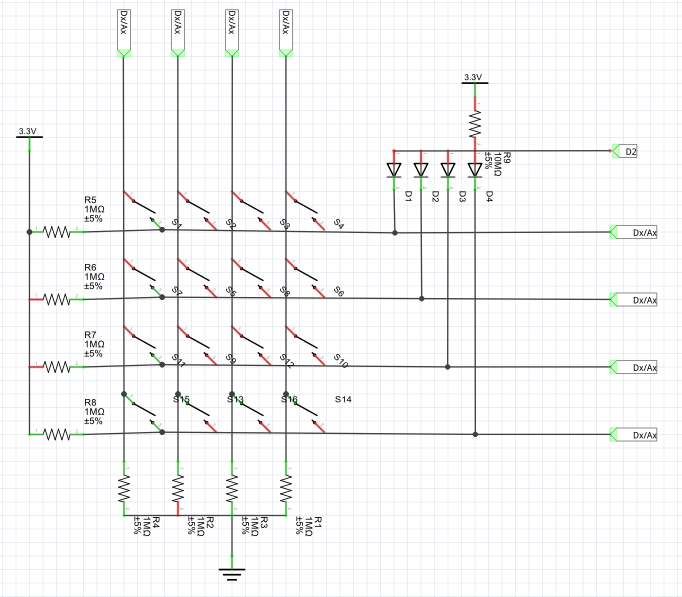
@drock1985 A quick drawing of a circuit which enables you to use only one interrupt...
When any of the keys is pressed you get an interrupt (FALLING) on D2. From that moment on you can poll the keyboard. Any of the digital and analog pins can be used for that purpose (except those in use by the radio..)
(you need to change the resistor values on the left side of the drawing to 10Mohm)
-
@drock1985 A quick drawing of a circuit which enables you to use only one interrupt...
When any of the keys is pressed you get an interrupt (FALLING) on D2. From that moment on you can poll the keyboard. Any of the digital and analog pins can be used for that purpose (except those in use by the radio..)
(you need to change the resistor values on the left side of the drawing to 10Mohm)
@AWI I have such a keypad 4x4 and I would like to use it with the famous my slim aa battery node. I think I understand your drawing. What I don't understand is what diodes do I need to use? I mean what type?
Also, if I was to include a green and red diode, or a bi-colour diode, what specifications would they need to have? Any links to the usual "shops"?
Thanks!
-
@AWI I have such a keypad 4x4 and I would like to use it with the famous my slim aa battery node. I think I understand your drawing. What I don't understand is what diodes do I need to use? I mean what type?
Also, if I was to include a green and red diode, or a bi-colour diode, what specifications would they need to have? Any links to the usual "shops"?
Thanks!
@karl261 You can use almost any diode, e.g a 1Nxxxx type
And for bi-color LED's many choices , just include a resistor (around 300ohm) in series.
-
Maybe a stupid question but why don't you change your keypad with a capacitive touch keypad ?
I have one of these and it's convenient, low power usage in sleep mode and one interrupt pin for keypress on any of the keys. Just make sure you only connect it to 3.3V, for power AND logic.
http://www.aliexpress.com/item/MPR121-Capacitive-Touch-Keypad-Shield-module-sensitive-key-keyboard/32642505921.html -
But in the end, I prefer the keypad I have. It looks nice.
Maybe this is the simplest solution? It turns the keypad into i2c:
https://www.hackster.io/venkatesh_rao/i2c-keypad-73a012 -
Ok, in the end I am stuck. So, I got the keypad working, no problem. But I cannot get it to trigger an interrupt. The PCF8574 has an interrupt pin, but it seems this does not work with this keypad. Or at least I could not figure out how to. So, my keypad speaks I2C now, but still has no interrupt capabilites.
Can anyone advise?
If not I will need to build the circuit from @AWI. Btw, in that circuit, Are ALL resistors 10 MOhm?
Or are R1-4 1 MOhm?
-
Few crazy solutions:
-
I put in an on / off switch. So before I type, I switch the whole thing on, wait until it registers with the gw, and then here we go. And then off. No need to sleep and wait for interrupts.
-
I can install a button device. So, the thing is sleeping, I press the button, the thing wakes up for 30 secs, that gives me time to type and send, and back it goes to sleep.
-
I have a 4x4 keypad. So, I don't need the ABCD. I could connect the ABCD in a way, that it acts like button device, so I can trigger the interrupt with ABCD, then type my number, and then it goes back to sleep.
-
-
@karl261 these options seem all very odd to me. I2c should work, did you activate a pull-up for the interrupt pin? Can you post your sketch and hardware connections?
@AWI Thanks for trying to help! Just a quick question first: Do I draw the circuit by hand or is there a good cheap (free) way to do it on the PC? Or tablet?
I think it is how the pcf8574 is designed. I detect no change on the interrupt pin. But yes, maybe my wiring is not good.
-
@AWI Thanks for trying to help! Just a quick question first: Do I draw the circuit by hand or is there a good cheap (free) way to do it on the PC? Or tablet?
I think it is how the pcf8574 is designed. I detect no change on the interrupt pin. But yes, maybe my wiring is not good.
-
@AWI Thanks for trying to help! Just a quick question first: Do I draw the circuit by hand or is there a good cheap (free) way to do it on the PC? Or tablet?
I think it is how the pcf8574 is designed. I detect no change on the interrupt pin. But yes, maybe my wiring is not good.
@karl261 As @mfalkvidd said. just make an simple hand drawing on how you connected the pfc8574 and the int pin. The rest is obvious. The pcf8574 can generate an interrupt on any change of the input pins.
-
@mfalkvidd Cool stuff, thanks!
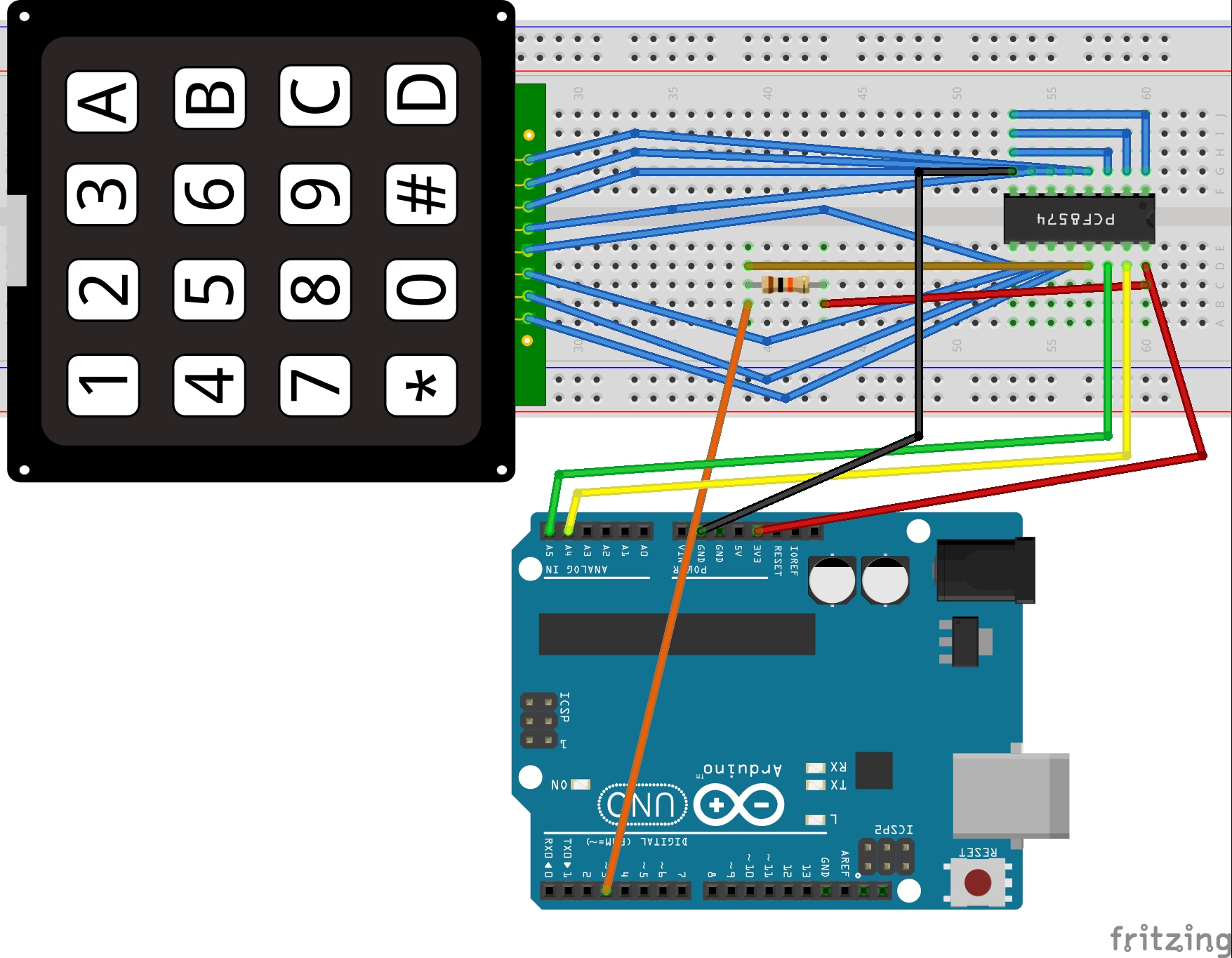
@AWI Here you go. What a chaos... Sorry. :-) I thought of a setup like this. But the interrupt pin of the pcf is not doing anything. Maybe I need another chip?
The resistor is 10kOhm.
NRF is also connected. And working.
The sketch is not ready, but the keyboard works on the serial line.
#include <Wire.h> #include <Keypad_I2C.h> #include <Keypad.h> #define I2CADDR 0x38 #define MY_DEBUG #define MY_RADIO_NRF24 #define MY_NODE_ID 8 #include <MySensors.h> #include <SPI.h> unsigned long SLEEP_TIME = 0; // Sleep time between reports (in milliseconds) #define DIGITAL_INPUT_SENSOR 3 // The digital input you attached your motion sensor. (Only 2 and 3 generates interrupt!) #define CHILD_ID 1 // Id of the sensor child const byte ROWS = 4; //four rows const byte COLS = 4; //three columns char keys[ROWS][COLS] = { {'1','2','3','A'}, {'4','5','6','B'}, {'7','8','9','C'}, {'*','0','#','D'} }; // Digitran keypad, bit numbers of PCF8574 i/o port byte rowPins[ROWS] = {0, 1, 2, 3}; //connect to the row pinouts of the keypad byte colPins[COLS] = {4, 5, 6, 7}; //connect to the column pinouts of the keypad Keypad_I2C kpd( makeKeymap(keys), rowPins, colPins, ROWS, COLS, I2CADDR, PCF8574 ); void setup(){ Wire.begin( ); kpd.begin( makeKeymap(keys) ); // Serial.begin(9600); Serial.println( "start" ); pinMode(DIGITAL_INPUT_SENSOR, INPUT); // sets the motion sensor digital pin as input } void loop(){ Serial.println("Waking up"); char key = kpd.getKey(); if (key){ Serial.println(key); } Serial.println("Good Night"); delay(100); sleep(digitalPinToInterrupt(DIGITAL_INPUT_SENSOR), FALLING, SLEEP_TIME); } -
@mfalkvidd Cool stuff, thanks!
@AWI Here you go. What a chaos... Sorry. :-) I thought of a setup like this. But the interrupt pin of the pcf is not doing anything. Maybe I need another chip?
The resistor is 10kOhm.
NRF is also connected. And working.
The sketch is not ready, but the keyboard works on the serial line.
#include <Wire.h> #include <Keypad_I2C.h> #include <Keypad.h> #define I2CADDR 0x38 #define MY_DEBUG #define MY_RADIO_NRF24 #define MY_NODE_ID 8 #include <MySensors.h> #include <SPI.h> unsigned long SLEEP_TIME = 0; // Sleep time between reports (in milliseconds) #define DIGITAL_INPUT_SENSOR 3 // The digital input you attached your motion sensor. (Only 2 and 3 generates interrupt!) #define CHILD_ID 1 // Id of the sensor child const byte ROWS = 4; //four rows const byte COLS = 4; //three columns char keys[ROWS][COLS] = { {'1','2','3','A'}, {'4','5','6','B'}, {'7','8','9','C'}, {'*','0','#','D'} }; // Digitran keypad, bit numbers of PCF8574 i/o port byte rowPins[ROWS] = {0, 1, 2, 3}; //connect to the row pinouts of the keypad byte colPins[COLS] = {4, 5, 6, 7}; //connect to the column pinouts of the keypad Keypad_I2C kpd( makeKeymap(keys), rowPins, colPins, ROWS, COLS, I2CADDR, PCF8574 ); void setup(){ Wire.begin( ); kpd.begin( makeKeymap(keys) ); // Serial.begin(9600); Serial.println( "start" ); pinMode(DIGITAL_INPUT_SENSOR, INPUT); // sets the motion sensor digital pin as input } void loop(){ Serial.println("Waking up"); char key = kpd.getKey(); if (key){ Serial.println(key); } Serial.println("Good Night"); delay(100); sleep(digitalPinToInterrupt(DIGITAL_INPUT_SENSOR), FALLING, SLEEP_TIME); } -
@karl261 Nice Job! I have to dive into the Keypad library to determine if the interrupt is activated... just give me a little longer ..
-
@karl261 It is a pretty hard to find where a possible cause is.. :confused:
What should happen to generate an interrupt is a change in one of the inputs. In a standard application the outputs (i.e. rows or colums) will be set to low and the inputs (colums or rows) pulled-up.
I can't figure out what the state of the row's/ column's is in the idle state from the library. YOu can probably measure if the rows en colums have a different level Sorry for now... -
@karl261 It is a pretty hard to find where a possible cause is.. :confused:
What should happen to generate an interrupt is a change in one of the inputs. In a standard application the outputs (i.e. rows or colums) will be set to low and the inputs (colums or rows) pulled-up.
I can't figure out what the state of the row's/ column's is in the idle state from the library. YOu can probably measure if the rows en colums have a different level Sorry for now...@AWI I don't recall that columns and rows have a different level. Of what I measured yesterday was that all 8 pins of the keyboard were at 3.3 V. So the only thing that happens is that there will be a connection made between column and row when a key is pressed. It seems that nothing is pulled up or down. :-/
So you think the ic can do it? Then we have to re-program the library... :-(
http://www.ti.com/lit/ds/symlink/pcf8574.pdf
On page 15 is a wiring example. Maybe we can learn something from this. Some pull up missing?EDIT: No, still can"t get it to work. Buh.
-
No progress....
Maybe this library is better to understand the pcf...
https://github.com/RobTillaart/Arduino/tree/master/libraries/PCF8574
Also here are some explanations (in German) and some code examples (in English)...
http://www.mikrocontroller.net/articles/Port-Expander_PCF8574
Hello! It looks like you're interested in this conversation, but you don't have an account yet.
Getting fed up of having to scroll through the same posts each visit? When you register for an account, you'll always come back to exactly where you were before, and choose to be notified of new replies (either via email, or push notification). You'll also be able to save bookmarks and upvote posts to show your appreciation to other community members.
With your input, this post could be even better 💗
Register Login