Problem getting the code to run with MySensors library 2.0
-
I believe the problem is a result of the pin 13 you are using for the Led. The Mysensor & SPI both require pin 13 (Pin 13 is SCK pin for SPI) for the radio communication. Try and move your Led Pin to another pin from Pin 8 downward.
@ayo
I did. The problem is still there. I also tried simplest of the simple LED blink code. Check my new post.Thank You
-
@palande.vaibhav said:
Even uncommenting #define MY_RADIO_NRF24 WORKS.
So the problem starts when I uncomment #include <MySensors.h>.
-
I just tested with older library version 1.5.4.
Both Blink and my Switch code work with MySensors library version 1.5.4 but doesn't work with version 2.0.
-
So I tired the blinking thing on my own Arduino setup using the MySensors 2.0 installed var the Arduino Library manager.
The Led blinks with the mysensors library attached.
// Enable debug prints to serial monitor
#define MY_DEBUG


// Enable and select radio type attached
#define MY_RADIO_NRF24
//#define MY_RADIO_RFM69

// Set LOW transmit power level as default, if you have an amplified NRF-module and
// power your radio separately with a good regulator you can turn up PA level.
#define MY_RF24_PA_LEVEL RF24_PA_LOW

// Enable serial gateway
#define MY_GATEWAY_SERIAL

// Define a lower baud rate for Arduino's running on 8 MHz (Arduino Pro Mini 3.3V & SenseBender)
#if F_CPU == 8000000L
#define MY_BAUD_RATE 38400
#endif

// Flash leds on rx/tx/err
#define MY_LEDS_BLINKING_FEATURE
// Set blinking period
#define MY_DEFAULT_LED_BLINK_PERIOD 300

// Inverses the behavior of leds
//#define MY_WITH_LEDS_BLINKING_INVERSE

// Enable inclusion mode
#define MY_INCLUSION_MODE_FEATURE
// Enable Inclusion mode button on gateway
#define MY_INCLUSION_BUTTON_FEATURE

// Inverses behavior of inclusion button (if using external pullup)
//#define MY_INCLUSION_BUTTON_EXTERNAL_PULLUP

// Set inclusion mode duration (in seconds)
#define MY_INCLUSION_MODE_DURATION 60
// Digital pin used for inclusion mode button
#define MY_INCLUSION_MODE_BUTTON_PIN  3

// Uncomment to override default HW configurations
//#define MY_DEFAULT_ERR_LED_PIN 4  // Error led pin
//#define MY_DEFAULT_RX_LED_PIN  6  // Receive led pin
//#define MY_DEFAULT_TX_LED_PIN  5  // the PCB, on board LED

#include <SPI.h>
#include <MySensors.h>

void setup() {
  // Setup locally attached sensors
  pinMode(8, OUTPUT);
}

void presentation() {
 // Present locally attached sensors
}

void loop() {
  // Send locally attached sensor data here
   digitalWrite(8, HIGH);   // turn the LED on (HIGH is the voltage level)
  wait(1000);              // wait for a second
  digitalWrite(8, LOW);    // turn the LED off by making the voltage LOW
  wait(1000);              // wait for a second
}
Maybe you can give that a short...
-
This post is deleted!
-
So I tired the blinking thing on my own Arduino setup using the MySensors 2.0 installed var the Arduino Library manager.
The Led blinks with the mysensors library attached.
// Enable debug prints to serial monitor
#define MY_DEBUG


// Enable and select radio type attached
#define MY_RADIO_NRF24
//#define MY_RADIO_RFM69

// Set LOW transmit power level as default, if you have an amplified NRF-module and
// power your radio separately with a good regulator you can turn up PA level.
#define MY_RF24_PA_LEVEL RF24_PA_LOW

// Enable serial gateway
#define MY_GATEWAY_SERIAL

// Define a lower baud rate for Arduino's running on 8 MHz (Arduino Pro Mini 3.3V & SenseBender)
#if F_CPU == 8000000L
#define MY_BAUD_RATE 38400
#endif

// Flash leds on rx/tx/err
#define MY_LEDS_BLINKING_FEATURE
// Set blinking period
#define MY_DEFAULT_LED_BLINK_PERIOD 300

// Inverses the behavior of leds
//#define MY_WITH_LEDS_BLINKING_INVERSE

// Enable inclusion mode
#define MY_INCLUSION_MODE_FEATURE
// Enable Inclusion mode button on gateway
#define MY_INCLUSION_BUTTON_FEATURE

// Inverses behavior of inclusion button (if using external pullup)
//#define MY_INCLUSION_BUTTON_EXTERNAL_PULLUP

// Set inclusion mode duration (in seconds)
#define MY_INCLUSION_MODE_DURATION 60
// Digital pin used for inclusion mode button
#define MY_INCLUSION_MODE_BUTTON_PIN  3

// Uncomment to override default HW configurations
//#define MY_DEFAULT_ERR_LED_PIN 4  // Error led pin
//#define MY_DEFAULT_RX_LED_PIN  6  // Receive led pin
//#define MY_DEFAULT_TX_LED_PIN  5  // the PCB, on board LED

#include <SPI.h>
#include <MySensors.h>

void setup() {
  // Setup locally attached sensors
  pinMode(8, OUTPUT);
}

void presentation() {
 // Present locally attached sensors
}

void loop() {
  // Send locally attached sensor data here
   digitalWrite(8, HIGH);   // turn the LED on (HIGH is the voltage level)
  wait(1000);              // wait for a second
  digitalWrite(8, LOW);    // turn the LED off by making the voltage LOW
  wait(1000);              // wait for a second
}
Maybe you can give that a short...
@ayo
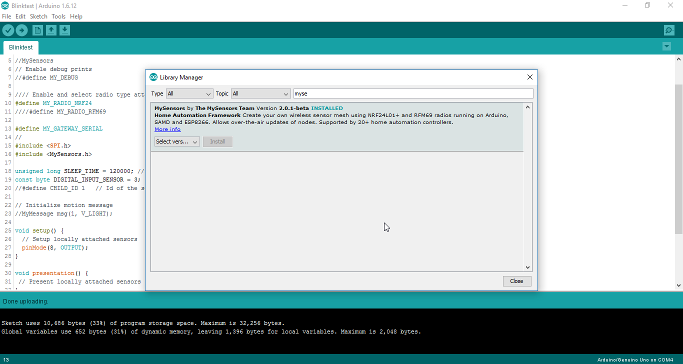
OK. I will give this a shot.One more thing is installing the library 2.0 from Arduino library manager gives an error "
CRC doesn't match. File is corrupted." I am using Arduino IDE version 1.6.12.I am downloading the zip from GitHub and pasting it in the Documents/Arduino/libraries folder. This is OK right??
-
So I tired the blinking thing on my own Arduino setup using the MySensors 2.0 installed var the Arduino Library manager.
The Led blinks with the mysensors library attached.
// Enable debug prints to serial monitor
#define MY_DEBUG


// Enable and select radio type attached
#define MY_RADIO_NRF24
//#define MY_RADIO_RFM69

// Set LOW transmit power level as default, if you have an amplified NRF-module and
// power your radio separately with a good regulator you can turn up PA level.
#define MY_RF24_PA_LEVEL RF24_PA_LOW

// Enable serial gateway
#define MY_GATEWAY_SERIAL

// Define a lower baud rate for Arduino's running on 8 MHz (Arduino Pro Mini 3.3V & SenseBender)
#if F_CPU == 8000000L
#define MY_BAUD_RATE 38400
#endif

// Flash leds on rx/tx/err
#define MY_LEDS_BLINKING_FEATURE
// Set blinking period
#define MY_DEFAULT_LED_BLINK_PERIOD 300

// Inverses the behavior of leds
//#define MY_WITH_LEDS_BLINKING_INVERSE

// Enable inclusion mode
#define MY_INCLUSION_MODE_FEATURE
// Enable Inclusion mode button on gateway
#define MY_INCLUSION_BUTTON_FEATURE

// Inverses behavior of inclusion button (if using external pullup)
//#define MY_INCLUSION_BUTTON_EXTERNAL_PULLUP

// Set inclusion mode duration (in seconds)
#define MY_INCLUSION_MODE_DURATION 60
// Digital pin used for inclusion mode button
#define MY_INCLUSION_MODE_BUTTON_PIN  3

// Uncomment to override default HW configurations
//#define MY_DEFAULT_ERR_LED_PIN 4  // Error led pin
//#define MY_DEFAULT_RX_LED_PIN  6  // Receive led pin
//#define MY_DEFAULT_TX_LED_PIN  5  // the PCB, on board LED

#include <SPI.h>
#include <MySensors.h>

void setup() {
  // Setup locally attached sensors
  pinMode(8, OUTPUT);
}

void presentation() {
 // Present locally attached sensors
}

void loop() {
  // Send locally attached sensor data here
   digitalWrite(8, HIGH);   // turn the LED on (HIGH is the voltage level)
  wait(1000);              // wait for a second
  digitalWrite(8, LOW);    // turn the LED off by making the voltage LOW
  wait(1000);              // wait for a second
}
Maybe you can give that a short...
@ayo
Something weird is happening right now. I am now running MySensors version 2.0. The code you gave works with library version 2.0.I was just experimenting with the lines of the code to see which line makes difference and I found that #define MY_GATEWAY_SERIAL line makes difference.
If I just add that line to my Blink code, it works with MySensors.hI don't know why this happens.
//// Enable debug prints to serial monitor
//#define MY_DEBUG
//
//
//// Enable and select radio type attached
#define MY_RADIO_NRF24
////#define MY_RADIO_RFM69
//
//// Set LOW transmit power level as default, if you have an amplified NRF-module and
//// power your radio separately with a good regulator you can turn up PA level.
//#define MY_RF24_PA_LEVEL RF24_PA_LOW
//
//// Enable serial gateway
#define MY_GATEWAY_SERIAL
//
//// Define a lower baud rate for Arduino's running on 8 MHz (Arduino Pro Mini 3.3V & SenseBender)
//#if F_CPU == 8000000L
//#define MY_BAUD_RATE 38400
//#endif
//
//// Flash leds on rx/tx/err
//#define MY_LEDS_BLINKING_FEATURE
//// Set blinking period
//#define MY_DEFAULT_LED_BLINK_PERIOD 300
//
//// Inverses the behavior of leds
////#define MY_WITH_LEDS_BLINKING_INVERSE
//
//// Enable inclusion mode
//#define MY_INCLUSION_MODE_FEATURE
//// Enable Inclusion mode button on gateway
//#define MY_INCLUSION_BUTTON_FEATURE
//
//// Inverses behavior of inclusion button (if using external pullup)
////#define MY_INCLUSION_BUTTON_EXTERNAL_PULLUP
//
//// Set inclusion mode duration (in seconds)
//#define MY_INCLUSION_MODE_DURATION 60
//// Digital pin used for inclusion mode button
//#define MY_INCLUSION_MODE_BUTTON_PIN  3

// Uncomment to override default HW configurations
//#define MY_DEFAULT_ERR_LED_PIN 4  // Error led pin
//#define MY_DEFAULT_RX_LED_PIN  6  // Receive led pin
//#define MY_DEFAULT_TX_LED_PIN  5  // the PCB, on board LED

#include <SPI.h>
#include <MySensors.h>

void setup() {
  // Setup locally attached sensors
  pinMode(8, OUTPUT);
}

void presentation() {
 // Present locally attached sensors
}

void loop() {
  // Send locally attached sensor data here
   digitalWrite(8, HIGH);   // turn the LED on (HIGH is the voltage level)
  delay(1000);              // wait for a second
  digitalWrite(8, LOW);    // turn the LED off by making the voltage LOW
  delay(1000);              // wait for a second
}
This code works but only if I have #define MY_GATEWAY_SERIAL line included. Can you try this on your setup?
In my code which was not working previously, If I just add #define MY_GATEWAY_SERIAL , it works.
In your Blink code, if you just comment out the line #define MY_GATEWAY_SERIAL, it won't work. Can you try this?
-
@ayo
Something weird is happening right now. I am now running MySensors version 2.0. The code you gave works with library version 2.0.I was just experimenting with the lines of the code to see which line makes difference and I found that #define MY_GATEWAY_SERIAL line makes difference.
If I just add that line to my Blink code, it works with MySensors.hI don't know why this happens.
//// Enable debug prints to serial monitor
//#define MY_DEBUG
//
//
//// Enable and select radio type attached
#define MY_RADIO_NRF24
////#define MY_RADIO_RFM69
//
//// Set LOW transmit power level as default, if you have an amplified NRF-module and
//// power your radio separately with a good regulator you can turn up PA level.
//#define MY_RF24_PA_LEVEL RF24_PA_LOW
//
//// Enable serial gateway
#define MY_GATEWAY_SERIAL
//
//// Define a lower baud rate for Arduino's running on 8 MHz (Arduino Pro Mini 3.3V & SenseBender)
//#if F_CPU == 8000000L
//#define MY_BAUD_RATE 38400
//#endif
//
//// Flash leds on rx/tx/err
//#define MY_LEDS_BLINKING_FEATURE
//// Set blinking period
//#define MY_DEFAULT_LED_BLINK_PERIOD 300
//
//// Inverses the behavior of leds
////#define MY_WITH_LEDS_BLINKING_INVERSE
//
//// Enable inclusion mode
//#define MY_INCLUSION_MODE_FEATURE
//// Enable Inclusion mode button on gateway
//#define MY_INCLUSION_BUTTON_FEATURE
//
//// Inverses behavior of inclusion button (if using external pullup)
////#define MY_INCLUSION_BUTTON_EXTERNAL_PULLUP
//
//// Set inclusion mode duration (in seconds)
//#define MY_INCLUSION_MODE_DURATION 60
//// Digital pin used for inclusion mode button
//#define MY_INCLUSION_MODE_BUTTON_PIN  3

// Uncomment to override default HW configurations
//#define MY_DEFAULT_ERR_LED_PIN 4  // Error led pin
//#define MY_DEFAULT_RX_LED_PIN  6  // Receive led pin
//#define MY_DEFAULT_TX_LED_PIN  5  // the PCB, on board LED

#include <SPI.h>
#include <MySensors.h>

void setup() {
  // Setup locally attached sensors
  pinMode(8, OUTPUT);
}

void presentation() {
 // Present locally attached sensors
}

void loop() {
  // Send locally attached sensor data here
   digitalWrite(8, HIGH);   // turn the LED on (HIGH is the voltage level)
  delay(1000);              // wait for a second
  digitalWrite(8, LOW);    // turn the LED off by making the voltage LOW
  delay(1000);              // wait for a second
}
This code works but only if I have #define MY_GATEWAY_SERIAL line included. Can you try this on your setup?
In my code which was not working previously, If I just add #define MY_GATEWAY_SERIAL , it works.
In your Blink code, if you just comment out the line #define MY_GATEWAY_SERIAL, it won't work. Can you try this?
@mfalkvidd
Any idea why this is happening?
Cause I can't use MY_GATEWAY_SERIAL for a node. Right? -
@mfalkvidd
Any idea why this is happening?
Cause I can't use MY_GATEWAY_SERIAL for a node. Right?@palande.vaibhav said:
Cause I can't use MY_GATEWAY_SERIAL for a node. Right?
Yes you can. But I read that there is a bug in MySensors 2.0 that causes the presentation function to not run, so you'll need the latest code from the MySensors development branch on Github.
-
Okay....so you are really having a strange problem here.
Am using the Arduino version 1.6.8,
Can you consider upgrading your arduino version maybe that could fix the CRC thing...1.6.8 is the older version. 1.6.12 is the latest version.
And the CRC error is the known bug. So, if your IDE and MySensors work then don't change anything.
-
Okay....so you are really having a strange problem here.
Am using the Arduino version 1.6.8,
Can you consider upgrading your arduino version maybe that could fix the CRC thing... -
@palande.vaibhav said:
Cause I can't use MY_GATEWAY_SERIAL for a node. Right?
Yes you can. But I read that there is a bug in MySensors 2.0 that causes the presentation function to not run, so you'll need the latest code from the MySensors development branch on Github.
@mfalkvidd said:
@palande.vaibhav said:
Cause I can't use MY_GATEWAY_SERIAL for a node. Right?
Yes you can. But I read that there is a bug in MySensors 2.0 that causes the presentation function to not run, so you'll need the latest code from the MySensors development branch on Github.
But am I right that for MySensors version 2.0, we must have #define MY_GATEWAY_SERIAL line in order for the code to work? OR is it just me?
And I don't even have anything in the presentation function. I think my problem is loop function not working if I don;t have #define MY_GATEWAY_SERIAL line in the code.
-
@palande.vaibhav said:
Cause I can't use MY_GATEWAY_SERIAL for a node. Right?
Yes you can. But I read that there is a bug in MySensors 2.0 that causes the presentation function to not run, so you'll need the latest code from the MySensors development branch on Github.
@mfalkvidd said:
@palande.vaibhav said:
Cause I can't use MY_GATEWAY_SERIAL for a node. Right?
Yes you can. But I read that there is a bug in MySensors 2.0 that causes the presentation function to not run, so you'll need the latest code from the MySensors development branch on Github.
I tried with the library from Development branch on GitHub. It still doesn't work.
I must have #define MY_GATEWAY_SERIAL line in the code for the code to work with MySensors.h.Library version:
Code below doesn't work cause I have commented #define MY_GATEWAY_SERIAL: Just uncomment it and the same code works
//MySensors // Enable debug prints //#define MY_DEBUG //// Enable and select radio type attached #define MY_RADIO_NRF24 ////#define MY_RADIO_RFM69 //#define MY_GATEWAY_SERIAL #include <SPI.h> #include <MySensors.h> unsigned long SLEEP_TIME = 120000; // Sleep time between reports (in milliseconds) const byte DIGITAL_INPUT_SENSOR = 3; // The digital input you attached your motion sensor. (Only 2 and 3 generates interrupt!) //#define CHILD_ID 1 // Id of the sensor child // Initialize motion message //MyMessage msg(1, V_LIGHT); void setup() { // Setup locally attached sensors pinMode(8, OUTPUT); } void presentation() { // Present locally attached sensors } void loop() { // Send locally attached sensor data here digitalWrite(8, HIGH); // turn the LED on (HIGH is the voltage level) delay(1000); // wait for a second digitalWrite(8, LOW); // turn the LED off by making the voltage LOW delay(1000); // wait for a second } -
@palande.vaibhav said:
Cause I can't use MY_GATEWAY_SERIAL for a node. Right?
Yes you can. But I read that there is a bug in MySensors 2.0 that causes the presentation function to not run, so you'll need the latest code from the MySensors development branch on Github.
I saw the post about the presentation function not working in 2.0. But that has been fixed in development version.
My problem is still there that code doesn't work at all. To which I think my loop function stops working if I don't have #define MY_GATEWAY_SERIAL line in the code.
-
I saw the post about the presentation function not working in 2.0. But that has been fixed in development version.
My problem is still there that code doesn't work at all. To which I think my loop function stops working if I don't have #define MY_GATEWAY_SERIAL line in the code.
-
@palande.vaibhav what does the debug output say?
You can also add a few Serial.println in the code to see where the execution stops.@mfalkvidd
Thanx for the suggestion. It's worse than I thought.Here is the code:
//MySensors
// Enable debug prints
//#define MY_DEBUG

//// Enable and select radio type attached
#define MY_RADIO_NRF24
////#define MY_RADIO_RFM69

#define MY_GATEWAY_SERIAL

#include <SPI.h>
#include <MySensors.h>

// Initialize motion message
//MyMessage msg(1, V_LIGHT);

void setup() {
  // Setup locally attached sensors
  pinMode(8, OUTPUT);
  Serial.println("Setup runs");
}

void presentation() {
 // Present locally attached sensors
 Serial.println("presentation runs");
}

void loop() {
  // Send locally attached sensor data here
  Serial.println("loop runs");
   digitalWrite(8, HIGH);   // turn the LED on (HIGH is the voltage level)
  delay(1000);              // wait for a second
  digitalWrite(8, LOW);    // turn the LED off by making the voltage LOW
  delay(1000);              // wait for a second
}
This is the output with #define MY_GATEWAY_SERIAL line.
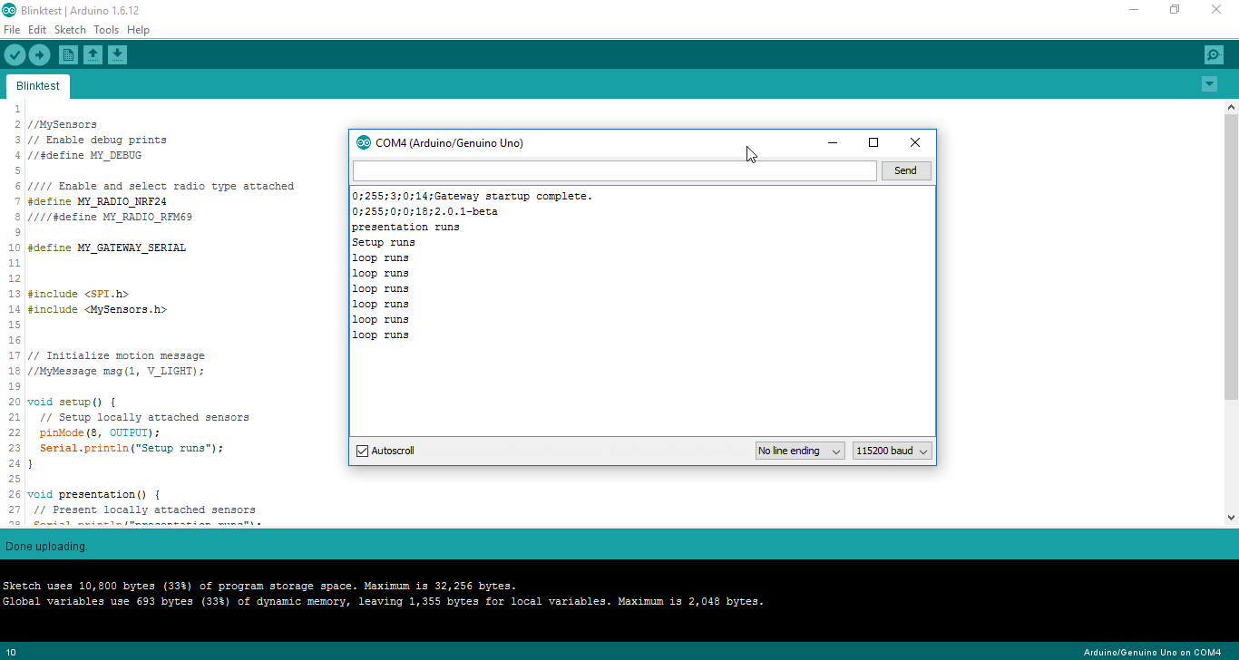
Without #define MY_GATEWAY_SERIAL, it doesn't show anything on the serial monitor.
-
@ayo
did you try commenting #define MY_GATEWAY_SERIAL and running your Blink code?
Can you please try that? -
@mfalkvidd
Thanx for the suggestion. It's worse than I thought.Here is the code:
//MySensors
// Enable debug prints
//#define MY_DEBUG

//// Enable and select radio type attached
#define MY_RADIO_NRF24
////#define MY_RADIO_RFM69

#define MY_GATEWAY_SERIAL

#include <SPI.h>
#include <MySensors.h>

// Initialize motion message
//MyMessage msg(1, V_LIGHT);

void setup() {
  // Setup locally attached sensors
  pinMode(8, OUTPUT);
  Serial.println("Setup runs");
}

void presentation() {
 // Present locally attached sensors
 Serial.println("presentation runs");
}

void loop() {
  // Send locally attached sensor data here
  Serial.println("loop runs");
   digitalWrite(8, HIGH);   // turn the LED on (HIGH is the voltage level)
  delay(1000);              // wait for a second
  digitalWrite(8, LOW);    // turn the LED off by making the voltage LOW
  delay(1000);              // wait for a second
}
This is the output with #define MY_GATEWAY_SERIAL line.
Without #define MY_GATEWAY_SERIAL, it doesn't show anything on the serial monitor.
@palande.vaibhav said:
@mfalkvidd
Thanx for the suggestion. It's worse than I thought.Here is the code:
//MySensors
// Enable debug prints
//#define MY_DEBUG

//// Enable and select radio type attached
#define MY_RADIO_NRF24
////#define MY_RADIO_RFM69

#define MY_GATEWAY_SERIAL

#include <SPI.h>
#include <MySensors.h>

// Initialize motion message
//MyMessage msg(1, V_LIGHT);

void setup() {
  // Setup locally attached sensors
  pinMode(8, OUTPUT);
  Serial.println("Setup runs");
}

void presentation() {
 // Present locally attached sensors
 Serial.println("presentation runs");
}

void loop() {
  // Send locally attached sensor data here
  Serial.println("loop runs");
   digitalWrite(8, HIGH);   // turn the LED on (HIGH is the voltage level)
  delay(1000);              // wait for a second
  digitalWrite(8, LOW);    // turn the LED off by making the voltage LOW
  delay(1000);              // wait for a second
}
This is the output with #define MY_GATEWAY_SERIAL line.
Without #define MY_GATEWAY_SERIAL, it doesn't show anything on the serial monitor.
@mfalkvidd Any update on this?
Hello! It looks like you're interested in this conversation, but you don't have an account yet.
Getting fed up of having to scroll through the same posts each visit? When you register for an account, you'll always come back to exactly where you were before, and choose to be notified of new replies (either via email, or push notification). You'll also be able to save bookmarks and upvote posts to show your appreciation to other community members.
With your input, this post could be even better 💗
Register Login