Wall mounted 'mood light' v2
-
@AWI
hi
for ir sensor i change sketch :#define MY_DEBUG #define MY_RADIO_NRF24 #define MY_RF24_CHANNEL 0 #define MY_NODE_ID 21 #define MY_REPEATER_FEATURE #include <SPI.h> #include <MySensors.h> #include <IRLib.h> int RECV_PIN = 8; #define CHILD_1 3 // childId IRsend irsend; IRrecv irrecv(RECV_PIN); IRdecode decoder; unsigned int Buffer[RAWBUF]; MyMessage msg(CHILD_1, V_VAR1); void setup() { irrecv.enableIRIn(); // Start the ir receiver decoder.UseExtnBuf(Buffer); } void presentation() { sendSketchInfo("IR Sensor", "1.0"); present(CHILD_1, S_DIMMER); } void loop() { if (irrecv.GetResults(&decoder)) { irrecv.resume(); decoder.decode(); decoder.DumpResults(); char buffer[10]; sprintf(buffer, "%08lx", decoder.value); send(msg.set(buffer)); } } void receive(const MyMessage &message) { int ID = message.sensor; int mySwitch = 0 ; Serial.print("Sensor: "); Serial.println(ID); switch (ID) { // If different sensors for this node case CHILD_1: // the number of the V_PERCENTAGE sensor to be controlled if (message.type == V_PERCENTAGE) { // Percentage indicates the pattern mySwitch = map(message.getInt(), 0, 100, 0, 15); // mapper dimmer values to Switch states 0..9 and wrap switch (mySwitch) { case 0: { irsend.send(NEC, 0x200848b7, 32); // whatever on switch action 0 } break ; case 1: { irsend.send(NEC, 0x2008c837, 32); // whatever on switch action 1 } break ; } break ; irrecv.enableIRIn(); } } }and in domoticz build a dimmer and when i set between 0-7 , code 1 is send . when set between 7-14 send code 2.
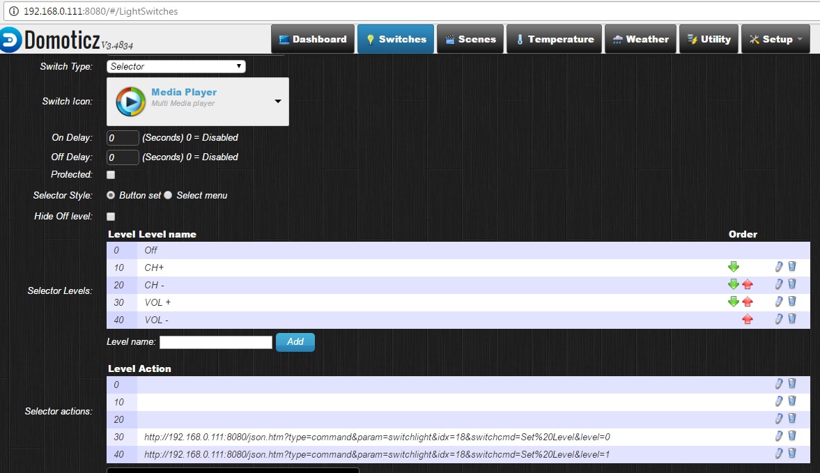
my idx for ir sensor is 18 and local ip is 192.168.0.111:8080
but for a virtual switch ( selector) , i type this code ( but dont work) what is my problem ?
http://192.168.0.111:8080/json.htm?type=command¶m=switchlight&idx=18&switchcmd=Set%7Level&level=0http://192.168.0.111:8080/json.htm?type=command¶m=switchlight&idx=18&switchcmd=Set %13Level&level=1
@Reza a first observation...there is an invalid character in both json commands (%7 and %13) change this to %20. So change:
http://192.168.0.111:8080/json.htm?type=command¶m=switchlight&idx=18&switchcmd=Set%13Level&level=1
to
http://192.168.0.111:8080/json.htm?type=command¶m=switchlight&idx=18&switchcmd=Set%20Level&level=1The
%20is the ASCII code for a space. -
also i change this lines in sketch :
present(CHILD_1, S_DIMMER);and
case CHILD_1:i dont know where is problem
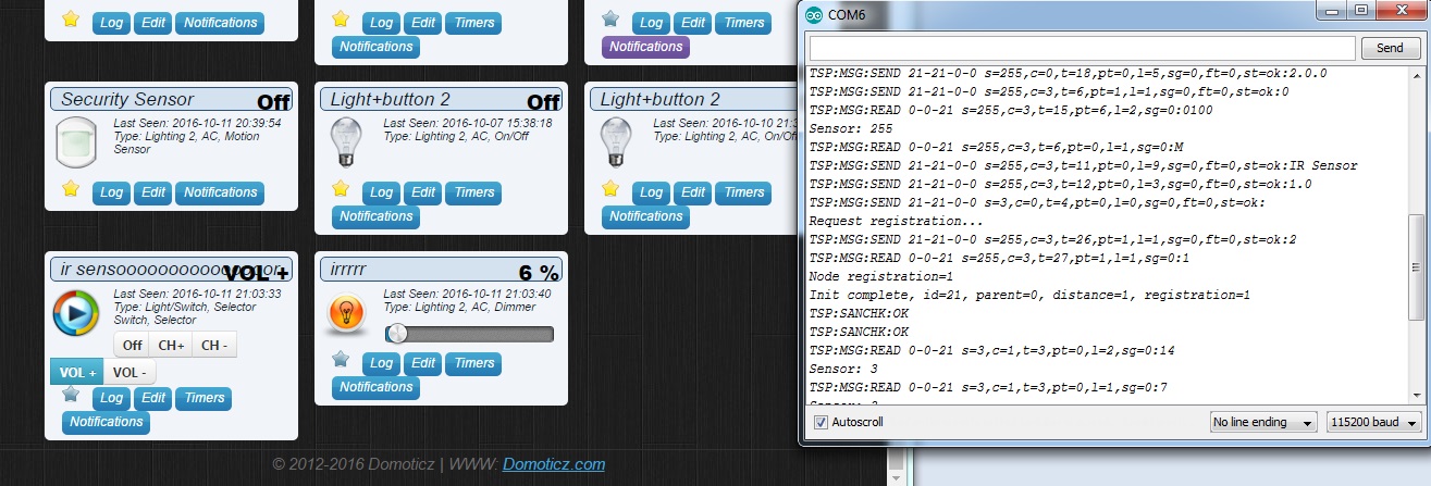
@Reza What does not work? I can read from (last few lines of) the serial output that you are receiving messages. Put a few Serial.prints() in the case statement below to show if you the structure is working.
switch (mySwitch) { case 0: { Serial.println("Entered case 0") ; irsend.send(NEC, 0x200848b7, 32); // whatever on switch action 0 } break ; case 1: { Serial.println("Entered case 1") ; irsend.send(NEC, 0x2008c837, 32); // whatever on switch action 1 } break ; case 2: { Serial.println("Entered case 2") ; irsend.send(NEC, 0x2008c837, 32); // whatever on switch action 2 } break ; } -
@Reza What does not work? I can read from (last few lines of) the serial output that you are receiving messages. Put a few Serial.prints() in the case statement below to show if you the structure is working.
switch (mySwitch) { case 0: { Serial.println("Entered case 0") ; irsend.send(NEC, 0x200848b7, 32); // whatever on switch action 0 } break ; case 1: { Serial.println("Entered case 1") ; irsend.send(NEC, 0x2008c837, 32); // whatever on switch action 1 } break ; case 2: { Serial.println("Entered case 2") ; irsend.send(NEC, 0x2008c837, 32); // whatever on switch action 2 } break ; }code is working well. in web dimmer (irrrrr) in pic is working, 6% is send code VOL+ and 13% is send code VOL -
but in selector virtual device(ir sensoooooooooooooooooooor, this is not work .when i push VOL + (in selector) dont send code and dont work. also VOL - -
Hello AWI,
great stuff!, you inspired my by posting this article to build similiar mood light.
for LED I've used ring 16 x LED ws2812b 5V neopixel.
Wiring:
"stripPin = 5" is connected to pin 4 on LED, which is "DIN - Control data signal input"Sketch used from this post. While compiling, I got following warnings, but think that that they should't cause a problem:
In file included from C:\Users\Jon\Documents\Arduino\libraries\FastLED/platforms/avr/fastled_avr.h:4:0,
                 from C:\Users\Jon\Documents\Arduino\libraries\FastLED/platforms.h:27,
                 from C:\Users\Jon\Documents\Arduino\libraries\FastLED/FastLED.h:52,
                 from C:\Users\Jon\Documents\Arduino\MySensors-Mood_light_v2.ino\MySensors-Mood_light_v2.ino.ino:55:
C:\Users\Jon\Documents\Arduino\libraries\FastLED/fastled_delay.h:37:0: warning: "NOP" redefined

 #  define NOP __asm__ __volatile__ ("cp r0,r0\n");

 ^

In file included from C:\Users\Jon\Documents\Arduino\libraries\MySensors/drivers/RF24/RF24.cpp:23:0,
                 from C:\Users\Jon\Documents\Arduino\libraries\MySensors/MySensors.h:242,
                 from C:\Users\Jon\Documents\Arduino\MySensors-Mood_light_v2.ino\MySensors-Mood_light_v2.ino.ino:53:
C:\Users\Jon\Documents\Arduino\libraries\MySensors/drivers/RF24/RF24.h:144:0: note: this is the location of the previous definition

 #define NOP             0xFF

 ^
In file included from C:\Users\Jon\Documents\Arduino\MySensors-Mood_light_v2.ino\MySensors-Mood_light_v2.ino.ino:55:0:

C:\Users\Jon\Documents\Arduino\libraries\FastLED/FastLED.h:17:21: note: #pragma message: FastLED version 3.001.003

 #    pragma message "FastLED version 3.001.003"

                     ^
Here's my node output from serial monitor:
Starting sensor (RNNNA-, 2.0.0)
TSM:INIT
TSM:RADIO:OK
TSP:ASSIGNID:OK (ID=62)
TSM:FPAR
TSP:MSG:SEND 62-62-255-255 s=255,c=3,t=7,pt=0,l=0,sg=0,ft=0,st=bc:
TSP:MSG:READ 0-0-62 s=255,c=3,t=8,pt=1,l=1,sg=0:0
TSP:MSG:FPAR RES (ID=0, dist=0)
TSP:MSG:PAR OK (ID=0, dist=1)
TSM:FPAR:OK
TSM:ID
TSM:CHKID:OK (ID=62)
TSM:UPL
TSP:PING:SEND (dest=0)
TSP:MSG:SEND 62-62-0-0 s=255,c=3,t=24,pt=1,l=1,sg=0,ft=0,st=ok:1
TSP:MSG:READ 0-0-62 s=255,c=3,t=25,pt=1,l=1,sg=0:1
TSP:MSG:PONG RECV (hops=1)
TSP:CHKUPL:OK
TSM:UPL:OK
TSM:READY
TSP:MSG:SEND 62-62-0-0 s=255,c=3,t=15,pt=6,l=2,sg=0,ft=0,st=ok:0100
TSP:MSG:SEND 62-62-0-0 s=255,c=0,t=17,pt=0,l=5,sg=0,ft=0,st=ok:2.0.0
TSP:MSG:SEND 62-62-0-0 s=255,c=3,t=6,pt=1,l=1,sg=0,ft=0,st=ok:0
TSP:MSG:READ 0-0-62 s=255,c=3,t=6,pt=0,l=1,sg=0:M
TSP:MSG:SEND 62-62-0-0 s=255,c=3,t=11,pt=0,l=17,sg=0,ft=0,st=ok:AWI RGB Wall W 62
TSP:MSG:SEND 62-62-0-0 s=255,c=3,t=12,pt=0,l=3,sg=0,ft=0,st=ok:2.0
TSP:MSG:SEND 62-62-0-0 s=1,c=0,t=26,pt=0,l=17,sg=0,ft=0,st=ok:RGB Wall RGB W 62
TSP:MSG:SEND 62-62-0-0 s=0,c=0,t=3,pt=0,l=19,sg=0,ft=0,st=ok:RGB Wall Light W 62
TSP:MSG:SEND 62-62-0-0 s=2,c=0,t=3,pt=0,l=25,sg=0,ft=0,st=ok:RGB Set Solid color (text
TSP:MSG:SEND 62-62-0-0 s=3,c=0,t=36,pt=0,l=23,sg=0,ft=0,st=ok:RGB Wall textcolor W 62
TSP:MSG:SEND 62-62-0-0 s=4,c=0,t=3,pt=0,l=19,sg=0,ft=0,st=ok:RGB Wall Alarm W 62
TSP:MSG:SEND 62-62-0-0 s=5,c=0,t=4,pt=0,l=21,sg=0,ft=0,st=ok:RGB Wall Pattern W 62
No registration required
Init complete, id=62, parent=0, distance=1, registration=1
Everything seems to be ok. For controller I use Domoticz, devices where discovered and added to controller .
Later on, on serial monitor I got:
TSP:MSG:SEND 62-62-0-0 s=255,c=3,t=22,pt=5,l=4,sg=0,ft=0,st=ok:57916
TSP:MSG:SEND 62-62-0-0 s=255,c=3,t=22,pt=5,l=4,sg=0,ft=0,st=ok:117917
.....
When I press the button I got:
TSP:MSG:SEND 62-62-0-0 s=0,c=1,t=2,pt=2,l=2,sg=0,ft=0,st=ok:1When pressed once more I got:
TSP:MSG:SEND 62-62-0-0 s=0,c=1,t=2,pt=2,l=2,sg=0,ft=0,st=ok:0Problem is, that later nothing happens (after shortly pressing the button - pin 4)
Only, when I press in Domoticz the leds starts to blink white/red in pulse mode (so wiring is ok?)
on serial monitor I got: ("st=fail:1"It's displayed 10 times)
TSP:MSG:READ 0-0-62 s=4,c=1,t=2,pt=0,l=1,sg=0:1
TSP:MSG:ACK msg
TSP:MSG:SEND 62-62-0-0 s=4,c=1,t=2,pt=0,l=1,sg=0,ft=0,st=ok:1
Sensor: 4
 Color: - Brightness: 127
TSP:MSG:READ 0-0-62 s=4,c=1,t=2,pt=0,l=1,sg=0:1
TSP:MSG:ACK msg
!TSP:MSG:SEND 62-62-0-0 s=4,c=1,t=2,pt=0,l=1,sg=0,ft=0,st=fail:1
Sensor: 4
Later i got a looot of times:
!TSM:UPL FAIL, SNP
TSM:FPAR
TSP:MSG:SEND 62-62-255-255 s=255,c=3,t=7,pt=0,l=0,sg=0,ft=0,st=bc:
TSP:MSG:READ 0-0-62 s=4,c=1,t=2,pt=0,l=1,sg=0:1
TSP:MSG:ACK msg
!TSP:SEND:TNR
Sensor: 4
 Color: - Brightness: 127
TSP:MSG:READ 0-0-62 s=4,c=1,t=2,pt=0,l=1,sg=0:1
TSP:MSG:ACK msg
!TSP:SEND:TNR
Sensor: 4
and @the end it seems that node stop responding:
!TSM:FPAR:FAIL
!TSM:FAILURE
TSM:PDT
TSM:INIT
When I press the button (pin 4) few times, long/short, then I got some random patterns, but node seems to be crashed and canno't be controlled from Domoticz.
I apriciate any kind of your supprot in my case.
Best
-
Hello AWI,
great stuff!, you inspired my by posting this article to build similiar mood light.
for LED I've used ring 16 x LED ws2812b 5V neopixel.
Wiring:
"stripPin = 5" is connected to pin 4 on LED, which is "DIN - Control data signal input"Sketch used from this post. While compiling, I got following warnings, but think that that they should't cause a problem:
In file included from C:\Users\Jon\Documents\Arduino\libraries\FastLED/platforms/avr/fastled_avr.h:4:0,
                 from C:\Users\Jon\Documents\Arduino\libraries\FastLED/platforms.h:27,
                 from C:\Users\Jon\Documents\Arduino\libraries\FastLED/FastLED.h:52,
                 from C:\Users\Jon\Documents\Arduino\MySensors-Mood_light_v2.ino\MySensors-Mood_light_v2.ino.ino:55:
C:\Users\Jon\Documents\Arduino\libraries\FastLED/fastled_delay.h:37:0: warning: "NOP" redefined

 #  define NOP __asm__ __volatile__ ("cp r0,r0\n");

 ^

In file included from C:\Users\Jon\Documents\Arduino\libraries\MySensors/drivers/RF24/RF24.cpp:23:0,
                 from C:\Users\Jon\Documents\Arduino\libraries\MySensors/MySensors.h:242,
                 from C:\Users\Jon\Documents\Arduino\MySensors-Mood_light_v2.ino\MySensors-Mood_light_v2.ino.ino:53:
C:\Users\Jon\Documents\Arduino\libraries\MySensors/drivers/RF24/RF24.h:144:0: note: this is the location of the previous definition

 #define NOP             0xFF

 ^
In file included from C:\Users\Jon\Documents\Arduino\MySensors-Mood_light_v2.ino\MySensors-Mood_light_v2.ino.ino:55:0:

C:\Users\Jon\Documents\Arduino\libraries\FastLED/FastLED.h:17:21: note: #pragma message: FastLED version 3.001.003

 #    pragma message "FastLED version 3.001.003"

                     ^
Here's my node output from serial monitor:
Starting sensor (RNNNA-, 2.0.0)
TSM:INIT
TSM:RADIO:OK
TSP:ASSIGNID:OK (ID=62)
TSM:FPAR
TSP:MSG:SEND 62-62-255-255 s=255,c=3,t=7,pt=0,l=0,sg=0,ft=0,st=bc:
TSP:MSG:READ 0-0-62 s=255,c=3,t=8,pt=1,l=1,sg=0:0
TSP:MSG:FPAR RES (ID=0, dist=0)
TSP:MSG:PAR OK (ID=0, dist=1)
TSM:FPAR:OK
TSM:ID
TSM:CHKID:OK (ID=62)
TSM:UPL
TSP:PING:SEND (dest=0)
TSP:MSG:SEND 62-62-0-0 s=255,c=3,t=24,pt=1,l=1,sg=0,ft=0,st=ok:1
TSP:MSG:READ 0-0-62 s=255,c=3,t=25,pt=1,l=1,sg=0:1
TSP:MSG:PONG RECV (hops=1)
TSP:CHKUPL:OK
TSM:UPL:OK
TSM:READY
TSP:MSG:SEND 62-62-0-0 s=255,c=3,t=15,pt=6,l=2,sg=0,ft=0,st=ok:0100
TSP:MSG:SEND 62-62-0-0 s=255,c=0,t=17,pt=0,l=5,sg=0,ft=0,st=ok:2.0.0
TSP:MSG:SEND 62-62-0-0 s=255,c=3,t=6,pt=1,l=1,sg=0,ft=0,st=ok:0
TSP:MSG:READ 0-0-62 s=255,c=3,t=6,pt=0,l=1,sg=0:M
TSP:MSG:SEND 62-62-0-0 s=255,c=3,t=11,pt=0,l=17,sg=0,ft=0,st=ok:AWI RGB Wall W 62
TSP:MSG:SEND 62-62-0-0 s=255,c=3,t=12,pt=0,l=3,sg=0,ft=0,st=ok:2.0
TSP:MSG:SEND 62-62-0-0 s=1,c=0,t=26,pt=0,l=17,sg=0,ft=0,st=ok:RGB Wall RGB W 62
TSP:MSG:SEND 62-62-0-0 s=0,c=0,t=3,pt=0,l=19,sg=0,ft=0,st=ok:RGB Wall Light W 62
TSP:MSG:SEND 62-62-0-0 s=2,c=0,t=3,pt=0,l=25,sg=0,ft=0,st=ok:RGB Set Solid color (text
TSP:MSG:SEND 62-62-0-0 s=3,c=0,t=36,pt=0,l=23,sg=0,ft=0,st=ok:RGB Wall textcolor W 62
TSP:MSG:SEND 62-62-0-0 s=4,c=0,t=3,pt=0,l=19,sg=0,ft=0,st=ok:RGB Wall Alarm W 62
TSP:MSG:SEND 62-62-0-0 s=5,c=0,t=4,pt=0,l=21,sg=0,ft=0,st=ok:RGB Wall Pattern W 62
No registration required
Init complete, id=62, parent=0, distance=1, registration=1
Everything seems to be ok. For controller I use Domoticz, devices where discovered and added to controller .
Later on, on serial monitor I got:
TSP:MSG:SEND 62-62-0-0 s=255,c=3,t=22,pt=5,l=4,sg=0,ft=0,st=ok:57916
TSP:MSG:SEND 62-62-0-0 s=255,c=3,t=22,pt=5,l=4,sg=0,ft=0,st=ok:117917
.....
When I press the button I got:
TSP:MSG:SEND 62-62-0-0 s=0,c=1,t=2,pt=2,l=2,sg=0,ft=0,st=ok:1When pressed once more I got:
TSP:MSG:SEND 62-62-0-0 s=0,c=1,t=2,pt=2,l=2,sg=0,ft=0,st=ok:0Problem is, that later nothing happens (after shortly pressing the button - pin 4)
Only, when I press in Domoticz the leds starts to blink white/red in pulse mode (so wiring is ok?)
on serial monitor I got: ("st=fail:1"It's displayed 10 times)
TSP:MSG:READ 0-0-62 s=4,c=1,t=2,pt=0,l=1,sg=0:1
TSP:MSG:ACK msg
TSP:MSG:SEND 62-62-0-0 s=4,c=1,t=2,pt=0,l=1,sg=0,ft=0,st=ok:1
Sensor: 4
 Color: - Brightness: 127
TSP:MSG:READ 0-0-62 s=4,c=1,t=2,pt=0,l=1,sg=0:1
TSP:MSG:ACK msg
!TSP:MSG:SEND 62-62-0-0 s=4,c=1,t=2,pt=0,l=1,sg=0,ft=0,st=fail:1
Sensor: 4
Later i got a looot of times:
!TSM:UPL FAIL, SNP
TSM:FPAR
TSP:MSG:SEND 62-62-255-255 s=255,c=3,t=7,pt=0,l=0,sg=0,ft=0,st=bc:
TSP:MSG:READ 0-0-62 s=4,c=1,t=2,pt=0,l=1,sg=0:1
TSP:MSG:ACK msg
!TSP:SEND:TNR
Sensor: 4
 Color: - Brightness: 127
TSP:MSG:READ 0-0-62 s=4,c=1,t=2,pt=0,l=1,sg=0:1
TSP:MSG:ACK msg
!TSP:SEND:TNR
Sensor: 4
and @the end it seems that node stop responding:
!TSM:FPAR:FAIL
!TSM:FAILURE
TSM:PDT
TSM:INIT
When I press the button (pin 4) few times, long/short, then I got some random patterns, but node seems to be crashed and canno't be controlled from Domoticz.
I apriciate any kind of your supprot in my case.
Best
@1kohm A lot of questions in ine post ;-)
Your node seems to be working, at least for a part. The red/white when you press the button is what should happen. The 'fail' messages indicate a transmission problem. Did you take the nescessary measures for the radio (i.e. capacitor)?
The warnings for fastled in the compiler can be ingnored. -
@AWI
I've tried to be detailed :)
Ok, here's how my radio and connections looks like:
Power suplly (5V, 3A) goes to RPi3 --> USB --> Arduino Uno gateway with radio (NRFL01+PA+LNA with 4,7uF 16V capacitor. Radio powered from 3,3V arduino pin). I've also tried with non amplified radio - the same result:(
3 devices (incl. gateway) connected via USB to RPi3. I've boosted current on RPi3 USB ports to 1,2A, by adding line:max_usb_curent=1to /boot/config.txt, but that didn't change anything.
Node is pro mini 5V, Radio NRFL01 has 4,7uF capacitor and 3,3 power supply goes from step-down regulator.
My other nodes (1 wire temp, lux metter, relay, DHT sensor) are working when connected without disturb.
For examlpe when I set:
Then RGB color is send to node, but after a while I canno't do anything more (communication crashes) and I got a lot of:
!TSP:MSG:PVER mismatch
TSP:MSG:READ 0-0-28 s=1,c=1,t=3,pt=0,l=0,sg=0:
Any advice will be apriciate
-
FIXED!
Happy :)Issue was so obvious...
I was supplying Neopixel LED's with 5V trought Arduino pro mini... so when node was starting everything was ok till sending light pattern to node. When data was send, LED's took to much Watts, and radio was crashing...
So now I just powered LED's with 5V parerall to the node ( LED's are supplied before node).Now, I need to understand your code, how "buttonPin" is working and how to set patterns. It seems that the code is acting wired sometimes, but I think that's due to my less knowledge about it now.
Thanks for guidlines!
-
@AWI
Amasing! I have been using your v1 sketch on 5 different nodes.
I was just about to make another one when i saw that you had released another version.I have made a similar hack to your v1 with a dimmer/selector switch in domoticz as pattern selector. But your code looks way better :)
-
If I wanted to add a effect like:
#include "FastLED.h"
#define NUM_LEDS 60
CRGB leds[NUM_LEDS];
#define PIN 6

void setup()
{
  FastLED.addLeds<WS2811, PIN, GRB>(leds, NUM_LEDS).setCorrection( TypicalLEDStrip );
}

// *** REPLACE FROM HERE ***
void loop() {
  // ---> here we call the effect function <---
}

// ---> here we define the effect function <---
// *** REPLACE TO HERE ***

void showStrip() {
 #ifdef ADAFRUIT_NEOPIXEL_H
   // NeoPixel
   strip.show();
 #endif
 #ifndef ADAFRUIT_NEOPIXEL_H
   // FastLED
   FastLED.show();
 #endif
}

void setPixel(int Pixel, byte red, byte green, byte blue) {
 #ifdef ADAFRUIT_NEOPIXEL_H
   // NeoPixel
   strip.setPixelColor(Pixel, strip.Color(red, green, blue));
 #endif
 #ifndef ADAFRUIT_NEOPIXEL_H
   // FastLED
   leds[Pixel].r = red;
   leds[Pixel].g = green;
   leds[Pixel].b = blue;
 #endif
}

void setAll(byte red, byte green, byte blue) {
  for(int i = 0; i < NUM_LEDS; i++ ) {
    setPixel(i, red, green, blue);
  }
  showStrip();
}
void loop() { SnowSparkle(0x10, 0x10, 0x10, 20, random(100,1000)); } void SnowSparkle(byte red, byte green, byte blue, int SparkleDelay, int SpeedDelay) { setAll(red,green,blue); int Pixel = random(NUM_LEDS); setPixel(Pixel,0xff,0xff,0xff); showStrip(); delay(SparkleDelay); setPixel(Pixel,red,green,blue); showStrip(); delay(SpeedDelay); }What would I need to change/add in the code?
-
Hi there, I am very happy with this project. Somehow with the transition to the current stable library (2.0) the lights won't turn off completely. I can't figure out what is wrong. Anyone has some suggestions?
@Jurik Happened to me too... change the auto increments in the
updateLightBrightness()routine to++actualBrightnessand--actualBrightness.See below
// Update the light brightness if time void updateLightBrightness(){ // global: curBrightness, actualBrightness, updateBrightnessDelay, lastBrightnessUpdate ; static byte actualBrightness ; // store real brightness state for slow dim unsigned long now = millis() ; if (now > lastBrightnessUpdate + updateBrightnessDelay){// check if time for update if ( actualBrightness > curBrightness) { FastLED.setBrightness( --actualBrightness); FastLED.show(); } else if ( actualBrightness < curBrightness){ FastLED.setBrightness( ++actualBrightness ); FastLED.show(); } lastBrightnessUpdate = now ; } } -
@AWI what does this mean: "const int numPixel = 16 ; // set to number of pixels (x top / y bottom)" ?
If I have a strip with 72 leds that are in a row up/down, should I just enter 72?I also can't figure out how to control the leds from domoticz. I have copied your sketch and I see the device in domoticz under nrf-radio-gateway (with 7 childs)
I have tried to create a dummy selector and have tried to add this:
http://192.168.0.175:8080/json.htm?type=command¶m=switchlight&idx=1094&switchcmd=Set Level&level=pFire
http://192.168.0.175:8080/json.htm?type=command¶m=switchlight&idx=1094&switchcmd=Set Level&level=0
http://192.168.0.175:8080/json.htm?type=command¶m=switchlight&idx=1094&switchcmd=Set Level&level=1
http://192.168.0.175:8080/json.htm?type=command¶m=switchlight&idx=1094&switchcmd=Set Level&level=2
http://192.168.0.175:8080/json.htm?type=command¶m=switchlight&idx=1094&switchcmd=Set Level&level=pOnBut nothing seams to work, I have also tried the commands directly in the chrome url bar with no effect. What am I missing?
-
Ahhh, the effects start at 4 ? when trying numbers 4-10 I get effects for most numbers but a few like 8-9 is blank and 0-2 turns strip off. When fiddeling about, I managed to get the alarm at number 4 to speed up somehow. I tried to read the sketch but cant quite understand.
-
@AWI Thanx for the advice! i will try it as soon as i get the chance. Great work!! thanx.
@Cliff-Karlsson Afaik, the numPixels correspond to the total number of leds combined with up/down or left/right. So 16 will make it an 8x8 wall light and 2 would make it a 1 by 1, 72 would make it 36x36. As far as the triggers in Domoticz, i am also new at this. I did manage to get the alarm running and the patterns through the dimmer function, but am unable to set up the patterns on a switch. Domoticz won't let me somehow. Will try to give this more prio.
Keep trying! and posting please
-
Hey @AWI
I have some trouble using this with MqTT messages.
I can get alarm to go off by sending a payload of '1' to 'InMQTT/62/4/1/0/2' and subsequently turn it off with any other value.But I can't get the rest of your functions to work!
If I read your code correct, to set a solid color I would have to send several MqTT messages to the children?
Ex, I would have to send 'InMQTT/62/1/1/0/40' and payload ex 'Candle' first.
Then 'InMQTT/62/1/1/0/2' with payload of '1' to turn it on?
I was looking at the serial protocol and do not find what V_Dimmer is for type. (https://www.mysensors.org/download/serial_api_20#variable-types)Anyways, i cant get it to work properly, maybe you could shed some light (pun not intended :+1: ) )?

Hello! It looks like you're interested in this conversation, but you don't have an account yet.
Getting fed up of having to scroll through the same posts each visit? When you register for an account, you'll always come back to exactly where you were before, and choose to be notified of new replies (either via email, or push notification). You'll also be able to save bookmarks and upvote posts to show your appreciation to other community members.
With your input, this post could be even better 💗
Register Login