Mysensors Gateway on OrangePi (Zero) (opi)
-
You are right, took the letter P, which is 16.... but is should have been A.... (for the 4.x kernel)
Updated the table!,Thx!!
@Tag Does the TMRh20 works in the way your radio is currently connected?
-
@Tag Does the TMRh20 works in the way your radio is currently connected?
@marceloaqno
The library compiled, but unfortunately i cannot get the examples for linux working.
need to edit i.e. gettingstarted.cpp with the correct pin setting, have tried a lot, but either it says that the radio is not connected, and if used with incorrect settings it will not compile at all....Maybe someone following this thread who has experince with this lib?
if there is any progress from my side will keep you posted... -
If you used this wiring scheme:
nRF24L01 | Orange Pi
_________|________________
VCC      | VCC3V3-EXT
GND      | GND
CSN      | SPI0_CS0 (SPI-CE0)
CE       | PA7 (IO-7)
MOSI     | SPI0_MOSI (SPI-MOSI)
SCK      | SPI0_CLK (SPI-CLK)
MISO     | SPI0_MISO (SPI-MISO)
Then you should initialize the radio with:
RF24 radio(7,0);Worked for me:
root@opi-pc-1:~/RF24-master/examples_linux# ./gettingstarted RF24/examples/GettingStarted/ STATUS = 0x0e RX_DR=0 TX_DS=0 MAX_RT=0 RX_P_NO=7 TX_FULL=0 RX_ADDR_P0-1 = 0x65646f4e32 0x65646f4e31 RX_ADDR_P2-5 = 0xc3 0xc4 0xc5 0xc6 TX_ADDR = 0x65646f4e32 RX_PW_P0-6 = 0x20 0x20 0x00 0x00 0x00 0x00 EN_AA = 0x3f EN_RXADDR = 0x02 RF_CH = 0x4c RF_SETUP = 0x07 CONFIG = 0x0e DYNPD/FEATURE = 0x00 0x00 Data Rate = 1MBPS Model = nRF24L01+ CRC Length = 16 bits PA Power = PA_MAX ************ Role Setup *********** Choose a role: Enter 0 for pong_back, 1 for ping_out (CTRL+C to exit) -
If you used this wiring scheme:
nRF24L01 | Orange Pi
_________|________________
VCC      | VCC3V3-EXT
GND      | GND
CSN      | SPI0_CS0 (SPI-CE0)
CE       | PA7 (IO-7)
MOSI     | SPI0_MOSI (SPI-MOSI)
SCK      | SPI0_CLK (SPI-CLK)
MISO     | SPI0_MISO (SPI-MISO)
Then you should initialize the radio with:
RF24 radio(7,0);Worked for me:
root@opi-pc-1:~/RF24-master/examples_linux# ./gettingstarted RF24/examples/GettingStarted/ STATUS = 0x0e RX_DR=0 TX_DS=0 MAX_RT=0 RX_P_NO=7 TX_FULL=0 RX_ADDR_P0-1 = 0x65646f4e32 0x65646f4e31 RX_ADDR_P2-5 = 0xc3 0xc4 0xc5 0xc6 TX_ADDR = 0x65646f4e32 RX_PW_P0-6 = 0x20 0x20 0x00 0x00 0x00 0x00 EN_AA = 0x3f EN_RXADDR = 0x02 RF_CH = 0x4c RF_SETUP = 0x07 CONFIG = 0x0e DYNPD/FEATURE = 0x00 0x00 Data Rate = 1MBPS Model = nRF24L01+ CRC Length = 16 bits PA Power = PA_MAX ************ Role Setup *********** Choose a role: Enter 0 for pong_back, 1 for ping_out (CTRL+C to exit)@mihai.aldea Could you try the repo I'm working on (https://github.com/marceloaqno/MySensors/tree/spidev marceloaqno-spidev) adding your settings to the examples_linux/mysgw.cpp?
#define MY_RF24_CE_PIN 7 #define MY_RF24_CS_PIN 0 -
If you used this wiring scheme:
nRF24L01 | Orange Pi
_________|________________
VCC      | VCC3V3-EXT
GND      | GND
CSN      | SPI0_CS0 (SPI-CE0)
CE       | PA7 (IO-7)
MOSI     | SPI0_MOSI (SPI-MOSI)
SCK      | SPI0_CLK (SPI-CLK)
MISO     | SPI0_MISO (SPI-MISO)
Then you should initialize the radio with:
RF24 radio(7,0);Worked for me:
root@opi-pc-1:~/RF24-master/examples_linux# ./gettingstarted RF24/examples/GettingStarted/ STATUS = 0x0e RX_DR=0 TX_DS=0 MAX_RT=0 RX_P_NO=7 TX_FULL=0 RX_ADDR_P0-1 = 0x65646f4e32 0x65646f4e31 RX_ADDR_P2-5 = 0xc3 0xc4 0xc5 0xc6 TX_ADDR = 0x65646f4e32 RX_PW_P0-6 = 0x20 0x20 0x00 0x00 0x00 0x00 EN_AA = 0x3f EN_RXADDR = 0x02 RF_CH = 0x4c RF_SETUP = 0x07 CONFIG = 0x0e DYNPD/FEATURE = 0x00 0x00 Data Rate = 1MBPS Model = nRF24L01+ CRC Length = 16 bits PA Power = PA_MAX ************ Role Setup *********** Choose a role: Enter 0 for pong_back, 1 for ping_out (CTRL+C to exit)Hmmm.... checked the docs again and guess what. the 26 pin header on the OPI Zero has SPI1.... instead of SPI0
Expansion Port
The Orange Pi Zero has a 26-pin, 0.1" unpopulated connector with several low-speed interfaces.
2x13 Header
1	3.3V	           2	5V
3	TWI0_SDA / PA12	   4	5V
5	TWI0_SCK / PA11	   6	GND
7	PWM1 / PA06	       8	UART1_TX / PG06
9	GND	               10	UART1_RX / PG07
11	UART2_RX / PA01	   12	SIM_CLK/PA_EINT7 / PA07
13	UART2_TX / PA00	   14	GND
15	UART2_CTS / PA03   16	TWI1-SDA / PA19
17	3.3V	           18	TWI1-SCK / PA18
19	SPI1_MOSI / PA15   20	GND
21	SPI1_MISO / PA16   22	UART2_RTS / PA02
23	SPI1_CLK / PA14    24	SPI1_CS / PA13
25	GND	               26	SIM_DET/PA_EINT10 / PA10
From http://linux-sunxi.org/Xunlong_Orange_Pi_Zero
If i look at /dev I only see spi0, which is most probably used for the onboard flash...root@orangepizero:/# ll /dev | grep -i spi crw------- 1 root root 153, 0 Jan 8 11:12 spidev0.0So now i need to figure out a way to get SPI1 up and running
-
@mihai.aldea Could you try the repo I'm working on (https://github.com/marceloaqno/MySensors/tree/spidev marceloaqno-spidev) adding your settings to the examples_linux/mysgw.cpp?
#define MY_RF24_CE_PIN 7 #define MY_RF24_CS_PIN 0@marceloaqno Here's the output:
./MySensors.h:258:2: error: #error No support for nRF24 radio on this platform #error No support for nRF24 radio on this platform ^ In file included from ./drivers/RF24/RF24.cpp:23:0, from ./MySensors.h:294, from examples_linux/mysgw.cpp:77: ./drivers/RF24/RF24.h:52:17: fatal error: SPI.h: No such file or directory #include <SPI.h> ^ compilation terminated. Makefile:98: recipe for target 'build/examples_linux/mysgw.o' failed make: *** [build/examples_linux/mysgw.o] Error 1 -
@Tag Use this info:
http://linux-sunxi.org/Sunxi-tools
To export /boot/script.bin, edit the output file and enable SPI1, then compile it back and reboot your OPi with the SPI1 active.If you haven't done this before, it's quite simple.
apt-get install sunxi-tools
cd ~
bin2fex /boot/script.bin > script.fex
Edit the script.fex file, find the [spi1] section and change spi_used = 0 to spi_used = 1. Save the file and exit.
Thenfex2bin script.fex > /boot/script.binReboot, then you should have the SPI1 active.
-
@marceloaqno
i have error yet
orangepi is a good board. please work at this board and run mysensors gateway on this, i follow this topic when you can fix this on orange pi . thank you -
@Tag Use this info:
http://linux-sunxi.org/Sunxi-tools
To export /boot/script.bin, edit the output file and enable SPI1, then compile it back and reboot your OPi with the SPI1 active.If you haven't done this before, it's quite simple.
apt-get install sunxi-tools
cd ~
bin2fex /boot/script.bin > script.fex
Edit the script.fex file, find the [spi1] section and change spi_used = 0 to spi_used = 1. Save the file and exit.
Thenfex2bin script.fex > /boot/script.binReboot, then you should have the SPI1 active.
Yep already found it :) problem was the old version of the tools, it was not able to decompile the script.bin file...
[update]
- modified the script file,
- changed spi_used = 1
- compiled back and rebooted
just 1 device file in called spidev0.0 no new device files are created..... :(
dmesg output:
[    0.814287] sunxi_spi_chan_cfg()1376 - [spi-0] has no spi_regulator.
[    0.814316] sunxi_spi_chan_cfg()1376 - [spi-1] has no spi_regulator.
[    0.815569] spi spi0: master is unqueued, this is deprecated
[    0.816776] spi spi1: master is unqueued, this is deprecated
Thx, will keep you posted!
-
@marceloaqno
i have error yet
orangepi is a good board. please work at this board and run mysensors gateway on this, i follow this topic when you can fix this on orange pi . thank you@Reza Was /sys/class/gpio/export created after modprobe gpio-sunxi?
@mihai-aldea Could you send the complete make and configure output so I can check if your system is correctly detected?
-
@Reza Was /sys/class/gpio/export created after modprobe gpio-sunxi?
@mihai-aldea Could you send the complete make and configure output so I can check if your system is correctly detected?
@marceloaqno said:
@mihai-aldea Could you send the complete make and configure output so I can check if your system is correctly detected?
Here it is
root@opi-pc-1:~/rf24opi/MySensors# ./configure --soc=H3 [OK] init system detected: systemd [SECTION] Saving configuration. [SECTION] Cleaning previous builds. [OK] Finished. root@opi-pc-1:~/rf24opi/MySensors# make gcc -MT build/drivers/Linux/log.o -MMD -MP -march=armv8-a -mtune=cortex-a53 -mfpu=neon-vfpv4 -mfloat-abi=hard -DMY_RADIO_NRF24 -DMY_GATEWAY_LINUX -DMY_DEBUG -Ofast -g -Wall -Wextra -I. -I./core -I./drivers/Linux -c drivers/Linux/log.c -o build/drivers/Linux/log.o g++ -MT build/drivers/Linux/IPAddress.o -MMD -MP -march=armv8-a -mtune=cortex-a53 -mfpu=neon-vfpv4 -mfloat-abi=hard -DMY_RADIO_NRF24 -DMY_GATEWAY_LINUX -DMY_DEBUG -Ofast -g -Wall -Wextra -I. -I./core -I./drivers/Linux -c drivers/Linux/IPAddress.cpp -o build/drivers/Linux/IPAddress.o g++ -MT build/drivers/Linux/noniso.o -MMD -MP -march=armv8-a -mtune=cortex-a53 -mfpu=neon-vfpv4 -mfloat-abi=hard -DMY_RADIO_NRF24 -DMY_GATEWAY_LINUX -DMY_DEBUG -Ofast -g -Wall -Wextra -I. -I./core -I./drivers/Linux -c drivers/Linux/noniso.cpp -o build/drivers/Linux/noniso.o g++ -MT build/drivers/Linux/Print.o -MMD -MP -march=armv8-a -mtune=cortex-a53 -mfpu=neon-vfpv4 -mfloat-abi=hard -DMY_RADIO_NRF24 -DMY_GATEWAY_LINUX -DMY_DEBUG -Ofast -g -Wall -Wextra -I. -I./core -I./drivers/Linux -c drivers/Linux/Print.cpp -o build/drivers/Linux/Print.o g++ -MT build/drivers/Linux/EthernetClient.o -MMD -MP -march=armv8-a -mtune=cortex-a53 -mfpu=neon-vfpv4 -mfloat-abi=hard -DMY_RADIO_NRF24 -DMY_GATEWAY_LINUX -DMY_DEBUG -Ofast -g -Wall -Wextra -I. -I./core -I./drivers/Linux -c drivers/Linux/EthernetClient.cpp -o build/drivers/Linux/EthernetClient.o g++ -MT build/drivers/Linux/compatibility.o -MMD -MP -march=armv8-a -mtune=cortex-a53 -mfpu=neon-vfpv4 -mfloat-abi=hard -DMY_RADIO_NRF24 -DMY_GATEWAY_LINUX -DMY_DEBUG -Ofast -g -Wall -Wextra -I. -I./core -I./drivers/Linux -c drivers/Linux/compatibility.cpp -o build/drivers/Linux/compatibility.o g++ -MT build/drivers/Linux/SerialPort.o -MMD -MP -march=armv8-a -mtune=cortex-a53 -mfpu=neon-vfpv4 -mfloat-abi=hard -DMY_RADIO_NRF24 -DMY_GATEWAY_LINUX -DMY_DEBUG -Ofast -g -Wall -Wextra -I. -I./core -I./drivers/Linux -c drivers/Linux/SerialPort.cpp -o build/drivers/Linux/SerialPort.o g++ -MT build/drivers/Linux/Stream.o -MMD -MP -march=armv8-a -mtune=cortex-a53 -mfpu=neon-vfpv4 -mfloat-abi=hard -DMY_RADIO_NRF24 -DMY_GATEWAY_LINUX -DMY_DEBUG -Ofast -g -Wall -Wextra -I. -I./core -I./drivers/Linux -c drivers/Linux/Stream.cpp -o build/drivers/Linux/Stream.o g++ -MT build/drivers/Linux/SoftEeprom.o -MMD -MP -march=armv8-a -mtune=cortex-a53 -mfpu=neon-vfpv4 -mfloat-abi=hard -DMY_RADIO_NRF24 -DMY_GATEWAY_LINUX -DMY_DEBUG -Ofast -g -Wall -Wextra -I. -I./core -I./drivers/Linux -c drivers/Linux/SoftEeprom.cpp -o build/drivers/Linux/SoftEeprom.o g++ -MT build/drivers/Linux/EthernetServer.o -MMD -MP -march=armv8-a -mtune=cortex-a53 -mfpu=neon-vfpv4 -mfloat-abi=hard -DMY_RADIO_NRF24 -DMY_GATEWAY_LINUX -DMY_DEBUG -Ofast -g -Wall -Wextra -I. -I./core -I./drivers/Linux -c drivers/Linux/EthernetServer.cpp -o build/drivers/Linux/EthernetServer.o g++ -MT build/examples_linux/mysgw.o -MMD -MP -march=armv8-a -mtune=cortex-a53 -mfpu=neon-vfpv4 -mfloat-abi=hard -DMY_RADIO_NRF24 -DMY_GATEWAY_LINUX -DMY_DEBUG -Ofast -g -Wall -Wextra -I. -I./core -I./drivers/Linux -c examples_linux/mysgw.cpp -o build/examples_linux/mysgw.o In file included from examples_linux/mysgw.cpp:77:0: ./MySensors.h:258:2: error: #error No support for nRF24 radio on this platform #error No support for nRF24 radio on this platform ^ In file included from ./drivers/RF24/RF24.cpp:23:0, from ./MySensors.h:294, from examples_linux/mysgw.cpp:77: ./drivers/RF24/RF24.h:52:17: fatal error: SPI.h: No such file or directory #include <SPI.h> ^ compilation terminated. Makefile:98: recipe for target 'build/examples_linux/mysgw.o' failed make: *** [build/examples_linux/mysgw.o] Error 1 -
@marceloaqno said:
@mihai-aldea Could you send the complete make and configure output so I can check if your system is correctly detected?
Here it is
root@opi-pc-1:~/rf24opi/MySensors# ./configure --soc=H3 [OK] init system detected: systemd [SECTION] Saving configuration. [SECTION] Cleaning previous builds. [OK] Finished. root@opi-pc-1:~/rf24opi/MySensors# make gcc -MT build/drivers/Linux/log.o -MMD -MP -march=armv8-a -mtune=cortex-a53 -mfpu=neon-vfpv4 -mfloat-abi=hard -DMY_RADIO_NRF24 -DMY_GATEWAY_LINUX -DMY_DEBUG -Ofast -g -Wall -Wextra -I. -I./core -I./drivers/Linux -c drivers/Linux/log.c -o build/drivers/Linux/log.o g++ -MT build/drivers/Linux/IPAddress.o -MMD -MP -march=armv8-a -mtune=cortex-a53 -mfpu=neon-vfpv4 -mfloat-abi=hard -DMY_RADIO_NRF24 -DMY_GATEWAY_LINUX -DMY_DEBUG -Ofast -g -Wall -Wextra -I. -I./core -I./drivers/Linux -c drivers/Linux/IPAddress.cpp -o build/drivers/Linux/IPAddress.o g++ -MT build/drivers/Linux/noniso.o -MMD -MP -march=armv8-a -mtune=cortex-a53 -mfpu=neon-vfpv4 -mfloat-abi=hard -DMY_RADIO_NRF24 -DMY_GATEWAY_LINUX -DMY_DEBUG -Ofast -g -Wall -Wextra -I. -I./core -I./drivers/Linux -c drivers/Linux/noniso.cpp -o build/drivers/Linux/noniso.o g++ -MT build/drivers/Linux/Print.o -MMD -MP -march=armv8-a -mtune=cortex-a53 -mfpu=neon-vfpv4 -mfloat-abi=hard -DMY_RADIO_NRF24 -DMY_GATEWAY_LINUX -DMY_DEBUG -Ofast -g -Wall -Wextra -I. -I./core -I./drivers/Linux -c drivers/Linux/Print.cpp -o build/drivers/Linux/Print.o g++ -MT build/drivers/Linux/EthernetClient.o -MMD -MP -march=armv8-a -mtune=cortex-a53 -mfpu=neon-vfpv4 -mfloat-abi=hard -DMY_RADIO_NRF24 -DMY_GATEWAY_LINUX -DMY_DEBUG -Ofast -g -Wall -Wextra -I. -I./core -I./drivers/Linux -c drivers/Linux/EthernetClient.cpp -o build/drivers/Linux/EthernetClient.o g++ -MT build/drivers/Linux/compatibility.o -MMD -MP -march=armv8-a -mtune=cortex-a53 -mfpu=neon-vfpv4 -mfloat-abi=hard -DMY_RADIO_NRF24 -DMY_GATEWAY_LINUX -DMY_DEBUG -Ofast -g -Wall -Wextra -I. -I./core -I./drivers/Linux -c drivers/Linux/compatibility.cpp -o build/drivers/Linux/compatibility.o g++ -MT build/drivers/Linux/SerialPort.o -MMD -MP -march=armv8-a -mtune=cortex-a53 -mfpu=neon-vfpv4 -mfloat-abi=hard -DMY_RADIO_NRF24 -DMY_GATEWAY_LINUX -DMY_DEBUG -Ofast -g -Wall -Wextra -I. -I./core -I./drivers/Linux -c drivers/Linux/SerialPort.cpp -o build/drivers/Linux/SerialPort.o g++ -MT build/drivers/Linux/Stream.o -MMD -MP -march=armv8-a -mtune=cortex-a53 -mfpu=neon-vfpv4 -mfloat-abi=hard -DMY_RADIO_NRF24 -DMY_GATEWAY_LINUX -DMY_DEBUG -Ofast -g -Wall -Wextra -I. -I./core -I./drivers/Linux -c drivers/Linux/Stream.cpp -o build/drivers/Linux/Stream.o g++ -MT build/drivers/Linux/SoftEeprom.o -MMD -MP -march=armv8-a -mtune=cortex-a53 -mfpu=neon-vfpv4 -mfloat-abi=hard -DMY_RADIO_NRF24 -DMY_GATEWAY_LINUX -DMY_DEBUG -Ofast -g -Wall -Wextra -I. -I./core -I./drivers/Linux -c drivers/Linux/SoftEeprom.cpp -o build/drivers/Linux/SoftEeprom.o g++ -MT build/drivers/Linux/EthernetServer.o -MMD -MP -march=armv8-a -mtune=cortex-a53 -mfpu=neon-vfpv4 -mfloat-abi=hard -DMY_RADIO_NRF24 -DMY_GATEWAY_LINUX -DMY_DEBUG -Ofast -g -Wall -Wextra -I. -I./core -I./drivers/Linux -c drivers/Linux/EthernetServer.cpp -o build/drivers/Linux/EthernetServer.o g++ -MT build/examples_linux/mysgw.o -MMD -MP -march=armv8-a -mtune=cortex-a53 -mfpu=neon-vfpv4 -mfloat-abi=hard -DMY_RADIO_NRF24 -DMY_GATEWAY_LINUX -DMY_DEBUG -Ofast -g -Wall -Wextra -I. -I./core -I./drivers/Linux -c examples_linux/mysgw.cpp -o build/examples_linux/mysgw.o In file included from examples_linux/mysgw.cpp:77:0: ./MySensors.h:258:2: error: #error No support for nRF24 radio on this platform #error No support for nRF24 radio on this platform ^ In file included from ./drivers/RF24/RF24.cpp:23:0, from ./MySensors.h:294, from examples_linux/mysgw.cpp:77: ./drivers/RF24/RF24.h:52:17: fatal error: SPI.h: No such file or directory #include <SPI.h> ^ compilation terminated. Makefile:98: recipe for target 'build/examples_linux/mysgw.o' failed make: *** [build/examples_linux/mysgw.o] Error 1@mihai.aldea I think you're not in the right branch, could you start from scratch like this:
rm -rf marceloaqno-spidev git clone https://github.com/marceloaqno/MySensors marceloaqno-spidev cd marceloaqno-spidev git checkout spidev ./configure make -
@Reza Was /sys/class/gpio/export created after modprobe gpio-sunxi?
@mihai-aldea Could you send the complete make and configure output so I can check if your system is correctly detected?
@marceloaqno
i have not any folder "gpio" in class folder .
what am i do ? :(
can you create a new topic with all steps after full fix on orange pi ?
thank you. i follow this topic -
@marceloaqno You were right, I wasn't using the correct branch. Your instructions though did not work for me
root@opi-pc-1:~# git clone https://github.com/marceloaqno/MySensors/tree/spidev marceloaqno-spidev
Cloning into 'marceloaqno-spidev'...
fatal: repository 'https://github.com/marceloaqno/MySensors/tree/spidev/' not found
Anyway, I found another way:
git clone https://github.com/marceloaqno/MySensors.git marceloaqno-spidev
cd marceloaqno-spidev/
git pull origin spidev
./configure
make
This time it compiled successfuly, but when I fired up mysgw all I got was:
mysgw: Starting gateway...
mysgw: Protocol version - 2.2.0-beta
with no other output.
Just to be sure we're on the same note, what is the wiring schematic I should use? When I first started to tinker with RF24 on OPi I found at least two wiring schematics.
For reference here's the gpio readall on my OPi PC:+-----+-----+----------+------+---+-Orange Pi+---+---+------+---------+-----+--+ | BCM | wPi | Name | Mode | V | Physical | V | Mode | Name | wPi | BCM | +-----+-----+----------+------+---+----++----+---+------+----------+-----+-----+ | | | 3.3v | | | 1 || 2 | | | 5v | | | | 12 | 8 | SDA.0 | ALT5 | 0 | 3 || 4 | | | 5V | | | | 11 | 9 | SCL.0 | ALT5 | 0 | 5 || 6 | | | 0v | | | | 6 | 7 | GPIO.7 | ALT3 | 0 | 7 || 8 | 0 | ALT4 | TxD3 | 15 | 13 | | | | 0v | | | 9 || 10 | 0 | ALT4 | RxD3 | 16 | 14 | | 1 | 0 | RxD2 | ALT5 | 0 | 11 || 12 | 0 | ALT3 | GPIO.1 | 1 | 110 | | 0 | 2 | TxD2 | ALT5 | 1 | 13 || 14 | | | 0v | | | | 3 | 3 | CTS2 | ALT5 | 0 | 15 || 16 | 0 | ALT3 | GPIO.4 | 4 | 68 | | | | 3.3v | | | 17 || 18 | 0 | ALT3 | GPIO.5 | 5 | 71 | | 64 | 12 | MOSI | ALT4 | 0 | 19 || 20 | | | 0v | | | | 65 | 13 | MISO | ALT4 | 0 | 21 || 22 | 0 | ALT5 | RTS2 | 6 | 2 | | 66 | 14 | SCLK | ALT4 | 0 | 23 || 24 | 0 | ALT4 | CE0 | 10 | 67 | | | | 0v | | | 25 || 26 | 0 | ALT3 | GPIO.11 | 11 | 21 | | 19 | 30 | SDA.1 | ALT4 | 0 | 27 || 28 | 0 | ALT4 | SCL.1 | 31 | 18 | | 7 | 21 | GPIO.21 | ALT3 | 0 | 29 || 30 | | | 0v | | | | 8 | 22 | GPIO.22 | ALT3 | 0 | 31 || 32 | 0 | ALT5 | RTS1 | 26 | 200 | | 9 | 23 | GPIO.23 | OUT | 0 | 33 || 34 | | | 0v | | | | 10 | 24 | GPIO.24 | OUT | 1 | 35 || 36 | 0 | ALT5 | CTS1 | 27 | 201 | | 20 | 25 | GPIO.25 | ALT3 | 0 | 37 || 38 | 0 | ALT5 | TxD1 | 28 | 198 | | | | 0v | | | 39 || 40 | 0 | ALT5 | RxD1 | 29 | 199 | +-----+-----+----------+------+---+----++----+---+------+----------+-----+-----+ | BCM | wPi | Name | Mode | V | Physical | V | Mode | Name | wPi | BCM | +-----+-----+----------+------+---+-Orange Pi+---+------+----------+-----+-----+ -
@marceloaqno You were right, I wasn't using the correct branch. Your instructions though did not work for me
root@opi-pc-1:~# git clone https://github.com/marceloaqno/MySensors/tree/spidev marceloaqno-spidev
Cloning into 'marceloaqno-spidev'...
fatal: repository 'https://github.com/marceloaqno/MySensors/tree/spidev/' not found
Anyway, I found another way:
git clone https://github.com/marceloaqno/MySensors.git marceloaqno-spidev
cd marceloaqno-spidev/
git pull origin spidev
./configure
make
This time it compiled successfuly, but when I fired up mysgw all I got was:
mysgw: Starting gateway...
mysgw: Protocol version - 2.2.0-beta
with no other output.
Just to be sure we're on the same note, what is the wiring schematic I should use? When I first started to tinker with RF24 on OPi I found at least two wiring schematics.
For reference here's the gpio readall on my OPi PC:+-----+-----+----------+------+---+-Orange Pi+---+---+------+---------+-----+--+ | BCM | wPi | Name | Mode | V | Physical | V | Mode | Name | wPi | BCM | +-----+-----+----------+------+---+----++----+---+------+----------+-----+-----+ | | | 3.3v | | | 1 || 2 | | | 5v | | | | 12 | 8 | SDA.0 | ALT5 | 0 | 3 || 4 | | | 5V | | | | 11 | 9 | SCL.0 | ALT5 | 0 | 5 || 6 | | | 0v | | | | 6 | 7 | GPIO.7 | ALT3 | 0 | 7 || 8 | 0 | ALT4 | TxD3 | 15 | 13 | | | | 0v | | | 9 || 10 | 0 | ALT4 | RxD3 | 16 | 14 | | 1 | 0 | RxD2 | ALT5 | 0 | 11 || 12 | 0 | ALT3 | GPIO.1 | 1 | 110 | | 0 | 2 | TxD2 | ALT5 | 1 | 13 || 14 | | | 0v | | | | 3 | 3 | CTS2 | ALT5 | 0 | 15 || 16 | 0 | ALT3 | GPIO.4 | 4 | 68 | | | | 3.3v | | | 17 || 18 | 0 | ALT3 | GPIO.5 | 5 | 71 | | 64 | 12 | MOSI | ALT4 | 0 | 19 || 20 | | | 0v | | | | 65 | 13 | MISO | ALT4 | 0 | 21 || 22 | 0 | ALT5 | RTS2 | 6 | 2 | | 66 | 14 | SCLK | ALT4 | 0 | 23 || 24 | 0 | ALT4 | CE0 | 10 | 67 | | | | 0v | | | 25 || 26 | 0 | ALT3 | GPIO.11 | 11 | 21 | | 19 | 30 | SDA.1 | ALT4 | 0 | 27 || 28 | 0 | ALT4 | SCL.1 | 31 | 18 | | 7 | 21 | GPIO.21 | ALT3 | 0 | 29 || 30 | | | 0v | | | | 8 | 22 | GPIO.22 | ALT3 | 0 | 31 || 32 | 0 | ALT5 | RTS1 | 26 | 200 | | 9 | 23 | GPIO.23 | OUT | 0 | 33 || 34 | | | 0v | | | | 10 | 24 | GPIO.24 | OUT | 1 | 35 || 36 | 0 | ALT5 | CTS1 | 27 | 201 | | 20 | 25 | GPIO.25 | ALT3 | 0 | 37 || 38 | 0 | ALT5 | TxD1 | 28 | 198 | | | | 0v | | | 39 || 40 | 0 | ALT5 | RxD1 | 29 | 199 | +-----+-----+----------+------+---+----++----+---+------+----------+-----+-----+ | BCM | wPi | Name | Mode | V | Physical | V | Mode | Name | wPi | BCM | +-----+-----+----------+------+---+-Orange Pi+---+------+----------+-----+-----+Just a question the command "gpio readall" does that does show the actual status of the system, or is it just a fixed table that is printed on screen....
Look at mine:
root@orangepizero:~# gpio readall
 +-----+-----+----------+------+---+-Orange Pi+---+---+------+---------+-----+--+
 | BCM | wPi |   Name   | Mode | V | Physical | V | Mode | Name     | wPi | BCM |
 +-----+-----+----------+------+---+----++----+---+------+----------+-----+-----+
 |     |     |     3.3v |      |   |  1 || 2  |   |      | 5v       |     |     |
 |  12 |   8 |    SDA.0 | ALT5 | 0 |  3 || 4  |   |      | 5V       |     |     |
 |  11 |   9 |    SCL.0 | ALT5 | 0 |  5 || 6  |   |      | 0v       |     |     |
 |   6 |   7 |   GPIO.7 | ALT3 | 0 |  7 || 8  | 1 | OUT  | TxD3     | 15  | 13  |
 |     |     |       0v |      |   |  9 || 10 | 0 | ALT5 | RxD3     | 16  | 14  |
 |   1 |   0 |     RxD2 | ALT5 | 0 | 11 || 12 | 0 | ALT3 | GPIO.1   | 1   | 110 |
 |   0 |   2 |     TxD2 | ALT5 | 0 | 13 || 14 |   |      | 0v       |     |     |
 |   3 |   3 |     CTS2 | ALT3 | 0 | 15 || 16 | 0 | ALT3 | GPIO.4   | 4   | 68  |
 |     |     |     3.3v |      |   | 17 || 18 | 0 | ALT3 | GPIO.5   | 5   | 71  |
 |  64 |  12 |     MOSI | ALT4 | 0 | 19 || 20 |   |      | 0v       |     |     |
 |  65 |  13 |     MISO | ALT4 | 0 | 21 || 22 | 0 | OUT  | RTS2     | 6   | 2   |
 |  66 |  14 |     SCLK | ALT4 | 0 | 23 || 24 | 0 | ALT4 | CE0      | 10  | 67  |
 |     |     |       0v |      |   | 25 || 26 | 0 | ALT3 | GPIO.11  | 11  | 21  |
 |  19 |  30 |    SDA.1 | ALT4 | 0 | 27 || 28 | 0 | ALT4 | SCL.1    | 31  | 18  |
 |   7 |  21 |  GPIO.21 | ALT3 | 0 | 29 || 30 |   |      | 0v       |     |     |
 |   8 |  22 |  GPIO.22 | ALT3 | 0 | 31 || 32 | 0 | ALT3 | RTS1     | 26  | 200 |
 |   9 |  23 |  GPIO.23 |  OUT | 0 | 33 || 34 |   |      | 0v       |     |     |
 |  10 |  24 |  GPIO.24 |  OUT | 1 | 35 || 36 | 0 | ALT3 | CTS1     | 27  | 201 |
 |  20 |  25 |  GPIO.25 |  OUT | 1 | 37 || 38 | 0 | ALT5 | TxD1     | 28  | 198 |
 |     |     |       0v |      |   | 39 || 40 | 0 | ALT5 | RxD1     | 29  | 199 |
 +-----+-----+----------+------+---+----++----+---+------+----------+-----+-----+
 | BCM | wPi |   Name   | Mode | V | Physical | V | Mode | Name     | wPi | BCM |
 +-----+-----+----------+------+---+-Orange Pi+---+------+----------+-----+-----+
It is the same... and shows 40 pins while the OPI Zero only has 26.......
There are some small differences between our tables in the naming column... so i guess it really reads the status / names of the pins.. Anyhow still strange that 40 pins are shown instead of 26 for the zero.. -
@marceloaqno: are you planning to create a pull request? also, like @Reza suggested i think it would be smart to gather all information somehwhere, unfortunately mysensors does not seem to have a wiki. can we write an article somehow? i could take care of that.
-
@marceloaqno: are you planning to create a pull request? also, like @Reza suggested i think it would be smart to gather all information somehwhere, unfortunately mysensors does not seem to have a wiki. can we write an article somehow? i could take care of that.
@mihai.aldea sorry about the github link mistake.
@pansen Yes, I will.
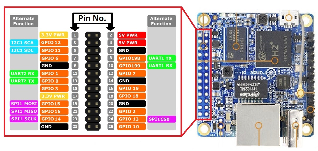
Is the orientation of the pins correct in the image?
-
@mihai.aldea sorry about the github link mistake.
@pansen Yes, I will.
Is the orientation of the pins correct in the image?
Nope pinout is reversed!,
The link below shows the correct one!
https://oshlab.com/orange-pi-zero-pinout/ -
Nope pinout is reversed!,
The link below shows the correct one!
https://oshlab.com/orange-pi-zero-pinout/@Tag Oops, did I get it right this time (I reuploaded the image)?
-
Build the RF24 lib, without erros on the OPI Zero. and am now able to start the tools and radio seems to be recognised!. (was a faulty breadboard wire.... :( )
Used the follwing to for the radio:
RF24 radio(2,0);Output from gettingstarted:
root@orangepizero:~/rf24libs/RF24/examples_linux# ./gettingstarted
RF24/examples/GettingStarted/
STATUS           = 0x00 RX_DR=0 TX_DS=0 MAX_RT=0 RX_P_NO=0 TX_FULL=0
RX_ADDR_P0-1     = 0x0000000000 0xff00000000
RX_ADDR_P2-5     = 0xff 0xff 0xff 0xff
TX_ADDR          = 0xffffffffff
RX_PW_P0-6       = 0xff 0xff 0xff 0xff 0xff 0xff
EN_AA            = 0xff
EN_RXADDR        = 0xff
RF_CH            = 0xbc
RF_SETUP         = 0xff
CONFIG           = 0xff
DYNPD/FEATURE    = 0xff 0xff
Data Rate        = 1MBPS
Model            = nRF24L01
CRC Length       = 16 bits
PA Power         = PA_MAX

 ************ Role Setup ***********
Choose a role: Enter 0 for pong_back, 1 for ping_out (CTRL+C to exit)
>
Hello! It looks like you're interested in this conversation, but you don't have an account yet.
Getting fed up of having to scroll through the same posts each visit? When you register for an account, you'll always come back to exactly where you were before, and choose to be notified of new replies (either via email, or push notification). You'll also be able to save bookmarks and upvote posts to show your appreciation to other community members.
With your input, this post could be even better 💗
Register Login