Mysensors Gateway on OrangePi (Zero) (opi)


  • Code Contributor

    @hausinger That shouldn't happen (gateway quitting itself). Could you submit the debug log with MY_DEBUG_VERBOSE_RF24 enabled?


  • @marceloaqno said:

    @hausinger That shouldn't happen (gateway quitting itself). Could you submit the debug log with MY_DEBUG_VERBOSE_RF24 enabled?

    Yes i can check that, but how?
    I tried it to enable it in "example_linux" => mysgw.cpp (added the line "#define MY_DEBUG_VERBOSE_RF24")
    I also tried it in the file: "MyConfig.h" (also added the line "#define MY_DEBUG_VERBOSE_RF24")

    But my output is still the same in the console.


  • @Tag Just to make it clear, do you want to connect the RF24 radio directly on the OPi's GPIO pins? Or do you want to connect it first to an Arduino and then to the OPi?
    I haven't used the mysgw because so far I only played with EasyIoT (directly attached RF24 to RPi GPIO - doesn't work on OPi) and MyController (using an Arduino connected to the OPi's serial port).
    Since MySensors is open source you can definitely change the pin numbers to match the OPI's Sunxi pin numbering. I don't have a setup in place right now to point you in the exact direction but will cook one tomorrow and get back with the details.
    Meanwhile you can burn the GatewaySerial sketch on your Arduino and either use /bin/mysgw or:

    apt-get -y update
    apt-get -y install minicom
    minicom -D /dev/ttyUSB0
    

    It's likely that the minicom will scramble the text on your screen but you can:

    Ctrl+Z
    O
    Screen and Keyboard
    T
    Esc
    Save setup as df1
    

    Close the minicom window then open it again and all should be fine.


  • @mihai.aldea

    Hi!, my idea is to have the NRF24 radio directly attached to the GPIO header on the OPI, (got this already working on my RPI system). So the idea is to run mysgw on the OPI system.
    (already got an extensive sensor network running with multiple arduinos and Mycontroller on thae RPI) On the RPI i had the arduino GW attached to USB and the NRF24 directly attached at the GPIO header at the same time, MyController saw 2 gateways ๐Ÿ™‚ )

    The other option like you already mentioned is to attach the arduino using USB read from /dev/ttyUSB0. I see this as a last resort only if mysgw will never run on the OPI zero.

    I read on the OPI website that the 26 pin header from the OPI is directly compatible with the RPI, however other sources of information tell me differently. So if you want to help out with the pin numbering this is greatly appreciated!

    but again mysgw on the OPI with the radio on the GPIO header would be great!!

    At this moment we try to build/compile mysgw on the OPI board, however that fails at the SPI part.

    Thanks!


  • Code Contributor

    @hausinger The problem you are having with your serial gateway (./configure --my-gateway=serial --my-serial-port=/dev/ttyUSB0 --my-serial-baudrate=115200) may be related to this bug:
    https://github.com/mysensors/MySensors/issues/720#issuecomment-270712256


  • @Tag I made the test setup and retraced my steps from the previous experiment. While the TMRh20 is working, the problem indeed lies with the ** mysgw** compilation. I'm getting the same error.
    After spending quite some time trying to mitigate the errors I hit a wall and I concluded that the problem is not the different pin numbering but the mysgw source code. I believe the problem is the lack of support for this architecture and with MySensors being so complex and my C++ skills so average, I'm afraid I can't help.
    However, if someone can mitigate the source code to successfully compile, the radio should be initialized with:
    RF24 radio(7, 0);
    7 - CE pin
    0 - CS pin
    More details here: https://github.com/TMRh20/RF24/issues/257


  • @mihai.aldea said:

    us experiment. While the TMRh20 is working, the problem indeed lies with the ** mysgw** compilation. I'm getting the same error.

    Thanks for the confirmation!!, now lets hope that mysgw, will be fixed/ported to the OPI boards soon!
    would be great to expand the number of systems it will run on..


  • @Tag
    Could you setup my sensors gateway on orange pi one? if you can please help me to build this . thank you


  • @Reza

    Unfortunately the mysgw software does not run native on the OPI systems at this moment.The only option today is to add an arduino to the USB port running i.e the serial gateway sketch (if you do not want to use the USB port, an other option would be using an UART trough the GPIO header, you data will show up on i.e. /dev/ttyS1 if UART 1 is used)

    step 2 will be to install controller software.
    (i tested MyController on the OPI and that works like a charm, and looks pretty cool!)

    See this link on how to build a serial gateway on the arduino. Using this setup you can follow the RaspberryPI tutorials.

    Hopefully mysgw will run soon on the OrangePI systems! think this is work in progress......


  • Code Contributor

    I'm trying to add support for Orange Pi to MySensors, this is the work-in-progress repository:
    https://github.com/marceloaqno/MySensors/tree/spidev

    It would be great if someone could test and submit results from the configure and make commands:

    git clone https://github.com/marceloaqno/MySensors marceloaqno-spidev
    cd marceloaqno-spidev
    git checkout spidev
    ./configure
    make


  • @marceloaqno

    Hi!, really appreciate your hard work on this!!, below are the results,
    (I was not able to execute the 1st command ๐Ÿ˜ž but... tried something else..

    root@orangepizero:~# git clone https://github.com/marceloaqno/MySensors.git marceloaqno-spidev
    Cloning into 'marceloaqno-spidev'...
    remote: Counting objects: 13834, done.
    remote: Compressing objects: 100% (26/26), done.
    remote: Total 13834 (delta 2), reused 0 (delta 0), pack-reused 13808
    Receiving objects: 100% (13834/13834), 9.67 MiB | 3.16 MiB/s, done.
    Resolving deltas: 100% (8289/8289), done.
    Checking connectivity... done.
    root@orangepizero:~# cd marceloaqno-spidev
    root@orangepizero:~/marceloaqno-spidev# git checkout spidev
    Branch spidev set up to track remote branch spidev from origin.
    Switched to a new branch 'spidev'

    root@orangepizero:~/marceloaqno-spidev# ./configure
    [SECTION] Detecting target machine.
    [OK] machine detected: SoC=H3, Type=unknown, CPU=armv7l.
    [SECTION] Detecting SPI driver.
    [OK] SPI driver detected:SPIDEV.
    [SECTION] Detecting init system.
    [OK] init system detected: systemd.
    [SECTION] Saving configuration.
    [SECTION] Cleaning previous builds.
    [OK] Finished.
    root@orangepizero:~/marceloaqno-spidev# make
    gcc -MT build/drivers/Linux/log.o -MMD -MP -march=armv8-a -mtune=cortex-a53 -mfpu=neon-vfpv4 -mfloat-abi=hard -DMY_RADIO_NRF24 -DMY_GATEWAY_LINUX -DMY_DEBUG -DLINUX_SPI_SPIDEV -DLINUX_GPIO_CAPABLE -Ofast -g -Wall -Wextra -I. -I./core -I./drivers/Linux -I./drivers/SPIDEV -c drivers/Linux/log.c -o build/drivers/Linux/log.o
    g++ -MT build/drivers/Linux/noniso.o -MMD -MP -march=armv8-a -mtune=cortex-a53 -mfpu=neon-vfpv4 -mfloat-abi=hard -DMY_RADIO_NRF24 -DMY_GATEWAY_LINUX -DMY_DEBUG -DLINUX_SPI_SPIDEV -DLINUX_GPIO_CAPABLE -Ofast -g -Wall -Wextra -I. -I./core -I./drivers/Linux -I./drivers/SPIDEV -c drivers/Linux/noniso.cpp -o build/drivers/Linux/noniso.o
    g++ -MT build/drivers/Linux/GPIO.o -MMD -MP -march=armv8-a -mtune=cortex-a53 -mfpu=neon-vfpv4 -mfloat-abi=hard -DMY_RADIO_NRF24 -DMY_GATEWAY_LINUX -DMY_DEBUG -DLINUX_SPI_SPIDEV -DLINUX_GPIO_CAPABLE -Ofast -g -Wall -Wextra -I. -I./core -I./drivers/Linux -I./drivers/SPIDEV -c drivers/Linux/GPIO.cpp -o build/drivers/Linux/GPIO.o
    g++ -MT build/drivers/Linux/Print.o -MMD -MP -march=armv8-a -mtune=cortex-a53 -mfpu=neon-vfpv4 -mfloat-abi=hard -DMY_RADIO_NRF24 -DMY_GATEWAY_LINUX -DMY_DEBUG -DLINUX_SPI_SPIDEV -DLINUX_GPIO_CAPABLE -Ofast -g -Wall -Wextra -I. -I./core -I./drivers/Linux -I./drivers/SPIDEV -c drivers/Linux/Print.cpp -o build/drivers/Linux/Print.o
    g++ -MT build/drivers/Linux/EthernetClient.o -MMD -MP -march=armv8-a -mtune=cortex-a53 -mfpu=neon-vfpv4 -mfloat-abi=hard -DMY_RADIO_NRF24 -DMY_GATEWAY_LINUX -DMY_DEBUG -DLINUX_SPI_SPIDEV -DLINUX_GPIO_CAPABLE -Ofast -g -Wall -Wextra -I. -I./core -I./drivers/Linux -I./drivers/SPIDEV -c drivers/Linux/EthernetClient.cpp -o build/drivers/Linux/EthernetClient.o
    g++ -MT build/drivers/Linux/SerialPort.o -MMD -MP -march=armv8-a -mtune=cortex-a53 -mfpu=neon-vfpv4 -mfloat-abi=hard -DMY_RADIO_NRF24 -DMY_GATEWAY_LINUX -DMY_DEBUG -DLINUX_SPI_SPIDEV -DLINUX_GPIO_CAPABLE -Ofast -g -Wall -Wextra -I. -I./core -I./drivers/Linux -I./drivers/SPIDEV -c drivers/Linux/SerialPort.cpp -o build/drivers/Linux/SerialPort.o
    g++ -MT build/drivers/Linux/Stream.o -MMD -MP -march=armv8-a -mtune=cortex-a53 -mfpu=neon-vfpv4 -mfloat-abi=hard -DMY_RADIO_NRF24 -DMY_GATEWAY_LINUX -DMY_DEBUG -DLINUX_SPI_SPIDEV -DLINUX_GPIO_CAPABLE -Ofast -g -Wall -Wextra -I. -I./core -I./drivers/Linux -I./drivers/SPIDEV -c drivers/Linux/Stream.cpp -o build/drivers/Linux/Stream.o
    g++ -MT build/drivers/Linux/IPAddress.o -MMD -MP -march=armv8-a -mtune=cortex-a53 -mfpu=neon-vfpv4 -mfloat-abi=hard -DMY_RADIO_NRF24 -DMY_GATEWAY_LINUX -DMY_DEBUG -DLINUX_SPI_SPIDEV -DLINUX_GPIO_CAPABLE -Ofast -g -Wall -Wextra -I. -I./core -I./drivers/Linux -I./drivers/SPIDEV -c drivers/Linux/IPAddress.cpp -o build/drivers/Linux/IPAddress.o
    g++ -MT build/drivers/Linux/compatibility.o -MMD -MP -march=armv8-a -mtune=cortex-a53 -mfpu=neon-vfpv4 -mfloat-abi=hard -DMY_RADIO_NRF24 -DMY_GATEWAY_LINUX -DMY_DEBUG -DLINUX_SPI_SPIDEV -DLINUX_GPIO_CAPABLE -Ofast -g -Wall -Wextra -I. -I./core -I./drivers/Linux -I./drivers/SPIDEV -c drivers/Linux/compatibility.cpp -o build/drivers/Linux/compatibility.o
    g++ -MT build/drivers/Linux/interrupt.o -MMD -MP -march=armv8-a -mtune=cortex-a53 -mfpu=neon-vfpv4 -mfloat-abi=hard -DMY_RADIO_NRF24 -DMY_GATEWAY_LINUX -DMY_DEBUG -DLINUX_SPI_SPIDEV -DLINUX_GPIO_CAPABLE -Ofast -g -Wall -Wextra -I. -I./core -I./drivers/Linux -I./drivers/SPIDEV -c drivers/Linux/interrupt.cpp -o build/drivers/Linux/interrupt.o
    g++ -MT build/drivers/Linux/SoftEeprom.o -MMD -MP -march=armv8-a -mtune=cortex-a53 -mfpu=neon-vfpv4 -mfloat-abi=hard -DMY_RADIO_NRF24 -DMY_GATEWAY_LINUX -DMY_DEBUG -DLINUX_SPI_SPIDEV -DLINUX_GPIO_CAPABLE -Ofast -g -Wall -Wextra -I. -I./core -I./drivers/Linux -I./drivers/SPIDEV -c drivers/Linux/SoftEeprom.cpp -o build/drivers/Linux/SoftEeprom.o
    g++ -MT build/drivers/Linux/EthernetServer.o -MMD -MP -march=armv8-a -mtune=cortex-a53 -mfpu=neon-vfpv4 -mfloat-abi=hard -DMY_RADIO_NRF24 -DMY_GATEWAY_LINUX -DMY_DEBUG -DLINUX_SPI_SPIDEV -DLINUX_GPIO_CAPABLE -Ofast -g -Wall -Wextra -I. -I./core -I./drivers/Linux -I./drivers/SPIDEV -c drivers/Linux/EthernetServer.cpp -o build/drivers/Linux/EthernetServer.o
    g++ -MT build/examples_linux/mysgw.o -MMD -MP -march=armv8-a -mtune=cortex-a53 -mfpu=neon-vfpv4 -mfloat-abi=hard -DMY_RADIO_NRF24 -DMY_GATEWAY_LINUX -DMY_DEBUG -DLINUX_SPI_SPIDEV -DLINUX_GPIO_CAPABLE -Ofast -g -Wall -Wextra -I. -I./core -I./drivers/Linux -I./drivers/SPIDEV -c examples_linux/mysgw.cpp -o build/examples_linux/mysgw.o
    /tmp/ccVhf8xP.s: Assembler messages:
    /tmp/ccVhf8xP.s:14808: Warning: IT blocks containing 32-bit Thumb instructions are deprecated in ARMv8
    g++ -MT build/drivers/SPIDEV/SPI.o -MMD -MP -march=armv8-a -mtune=cortex-a53 -mfpu=neon-vfpv4 -mfloat-abi=hard -DMY_RADIO_NRF24 -DMY_GATEWAY_LINUX -DMY_DEBUG -DLINUX_SPI_SPIDEV -DLINUX_GPIO_CAPABLE -Ofast -g -Wall -Wextra -I. -I./core -I./drivers/Linux -I./drivers/SPIDEV -c drivers/SPIDEV/SPI.cpp -o build/drivers/SPIDEV/SPI.o
    g++ -pthread -o bin/mysgw build/drivers/Linux/log.o build/drivers/Linux/noniso.o build/drivers/Linux/GPIO.o build/drivers/Linux/Print.o build/drivers/Linux/EthernetClient.o build/drivers/Linux/SerialPort.o build/drivers/Linux/Stream.o build/drivers/Linux/IPAddress.o build/drivers/Linux/compatibility.o build/drivers/Linux/interrupt.o build/drivers/Linux/SoftEeprom.o build/drivers/Linux/EthernetServer.o build/examples_linux/mysgw.o build/drivers/SPIDEV/SPI.o

    root@orangepizero:~/marceloaqno-spidev# ll bin
    total 640
    -rwxr-xr-x 1 root root 654544 Jan 7 22:48 mysgw

    Seems we have a binary!!
    ๐Ÿ˜„


  • @marceloaqno

    Just hooked up a radio to the GPIO header. (used this link for the model 1 RPI https://www.mysensors.org/build/raspberry and attached the interrupt pin also to pin 15)

    This is the result i get
    root@orangepizero:~/marceloaqno-spidev/bin# mysgw
    mysgw: Starting gateway...
    mysgw: Protocol version - 2.2.0-beta
    mysgw: Could not open /sys/class/gpio/gpio10/direction
    Illegal instruction
    root@orangepizero:~/marceloaqno-spidev/bin#


  • Code Contributor

    @Tag Great! The mapping of the physical GPIO number in OrangePi is not ready yet, so you need to figure out the correct value for the CE and CSN pins by adding this to the examples_linux/mysgw.cpp or MyConfig.h

    #define MY_RF24_CE_PIN X
    #define MY_RF24_CS_PIN Y
    

    This is the best pinout image I've found that could help:
    https://oshlab.com/orange-pi-zero-pinout/

    This may also give you some hint:

    cat /sys/kernel/debug/gpio
    

  • Code Contributor

    @Tag Maybe this one can help too:
    http://orange314.com/WiringOP


  • Code Contributor

    @Tag also, please don't set the interrupt pin for now.


  • Code Contributor

    @Tag I found more information on the wiki page about the gpio pins:
    http://linux-sunxi.org/GPIO

    It seems that there is a calculation to be made to know which number to use ๐Ÿ˜ฑ


  • @marceloaqno

    Hi!!, many thanks for the info!! really helpful!
    Made some progress. first I created this table based on this page: http://linux-sunxi.org/GPIO

    Pin - Num - Name - Calculated value A=1 ((1-1)*32 + Pin)
    CE / 22 / PA02 / 2
    SCK / 23 / PA14 / 14
    MISO / 21 / PA16 / 16
    CSN / 24 / PA13 / 13
    MOSI / 19 / PA15 / 15

    Now it is important that you know which kernel is used on your systems the 4.x architecture is different compared to the 3.x arch...

    If the 4.x kernel is used you need to use the calculated value for the GPIO pin numbering, i could not test that since I am using the 3.x kernel, so this is what i did:

    1. load the GPIO kernel module:
    modprobe gpio-sunxi
    
    1. Create the GPIO device files since these were not available on my system by default.
    for A in 1 2 3 4 5 6 7 8 9 10 11 12; do echo "$A" > /sys/class/gpio/export ; done
    

    This created the following entries in /sys/class/gpio

    root@orangepizero:~/marceloaqno-spidev/bin# ls -l /sys/class/gpio
    total 0
    --w------- 1 root root 4096 Jan  8 07:39 export
    lrwxrwxrwx 1 root root    0 Jan  8 07:16 gpio1 -> ../../devices/platform/sunxi-pinctrl/gpio/gpio1
    lrwxrwxrwx 1 root root    0 Jan  8 07:16 gpio11 -> ../../devices/platform/sunxi-pinctrl/gpio/gpio11
    lrwxrwxrwx 1 root root    0 Jan  8 07:16 gpio12 -> ../../devices/platform/sunxi-pinctrl/gpio/gpio12
    lrwxrwxrwx 1 root root    0 Jan  8 07:32 gpio13 -> ../../devices/platform/sunxi-pinctrl/gpio/gpio13
    lrwxrwxrwx 1 root root    0 Jan  8 07:16 gpio2 -> ../../devices/platform/sunxi-pinctrl/gpio/gpio2
    lrwxrwxrwx 1 root root    0 Jan  8 07:16 gpio3 -> ../../devices/platform/sunxi-pinctrl/gpio/gpio3
    lrwxrwxrwx 1 root root    0 Jan  8 07:16 gpio4 -> ../../devices/platform/sunxi-pinctrl/gpio/gpio4
    lrwxrwxrwx 1 root root    0 Jan  8 07:16 gpio5 -> ../../devices/platform/sunxi-pinctrl/gpio/gpio5
    lrwxrwxrwx 1 root root    0 Jan  8 07:16 gpio6 -> ../../devices/platform/sunxi-pinctrl/gpio/gpio6
    lrwxrwxrwx 1 root root    0 Jan  8 07:16 gpio7 -> ../../devices/platform/sunxi-pinctrl/gpio/gpio7
    lrwxrwxrwx 1 root root    0 Jan  8 07:16 gpio8 -> ../../devices/platform/sunxi-pinctrl/gpio/gpio8
    lrwxrwxrwx 1 root root    0 Jan  8 07:16 gpio9 -> ../../devices/platform/sunxi-pinctrl/gpio/gpio9
    lrwxrwxrwx 1 root root    0 Jan  1  1970 gpiochip0 -> ../../devices/platform/sunxi-pinctrl/gpio/gpiochip0
    --w------- 1 root root 4096 Jan  1  1970 unexport
    

    Modified mysgw.cpp to use:

    #define MY_RF24_CE_PIN 2
    #define MY_RF24_CS_PIN 13
    

    And did a clean build:

    make clean
    ./configure
    make
    

    Now some thing has changed! ๐Ÿ™‚

    root@orangepizero:~/marceloaqno-spidev/bin# ./mysgw -d
    mysgw: Starting gateway...
    mysgw: Protocol version - 2.2.0-beta
    mysgw: MCO:BGN:INIT GW,CP=RNNG---,VER=2.2.0-beta
    mysgw: TSM:INIT
    mysgw: TSF:WUR:MS=0
    mysgw: !TSM:INIT:TSP FAIL
    mysgw: TSM:FAIL:CNT=1
    mysgw: TSM:FAIL:PDT
    

    Will do some more testing with an LED today see if the GPIO pin numbering that was created is okay,

    will keep you posted!:


  • @marceloaqno
    Did some testing,

    Setup the GPIO pins:

    modprobe gpio-sunxi
    
    for A in 1 2 3 4 5 6 7 8 9 10 11 12 13 14 15 16 
    do echo "$A" > /sys/class/gpio/export
    done
    

    (The device files that are created by the commands above do not survive a reboot, so remember to execute the above commands after each reboot!)

    Hooked up an led between ground and i.e. pin 22, this pin is linked to GPIO2

    Then:

    echo out > /sys/class/gpio/gpio2/direction
    echo 1 > /sys/class/gpio/gpio2/value
    echo 0 > /sys/class/gpio/gpio2/value


    And eureka!! Led went on and off ๐Ÿ˜„

    Did this for all GPIO ports used by mysgw, below is the verified pin / GPIO table

    Pin#  -  GPIO / NRF24 
    22 - GPIO2   / CE
    23 - GPIO14  / SCK
    21 - GPIO16  / MISO
    24 - GPIO13  / CSN
    19 - GPIO15  / MOSI
    

    Tested all pins and led went on and off on all

    How i connected the radio: https://www.mysensors.org/build/raspberry (see the Pi1 part)
    How to setup GPIO: http://linux-sunxi.org/GPIO (3.x kernel part, and added pin 13/14/15/16)
    Pinout for the OPI Zero: https://i1.wp.com/oshlab.com/wp-content/uploads/2016/11/Orange-Pi-Zero-Pinout-banner2.jpg?fit=1200%2C628&ssl=1 (carefully look at the pin numbering!)

    Maybe it is usefull, I rebuild mysgw with NRF24 radio debugging enabled, this is the output I get:

    root@orangepizero:~/marceloaqno-spidev/bin# ./mysgw -d
    mysgw: Starting gateway...
    mysgw: Protocol version - 2.2.0-beta
    mysgw: MCO:BGN:INIT GW,CP=RNNG---,VER=2.2.0-beta
    mysgw: TSM:INIT
    mysgw: TSF:WUR:MS=0
    mysgw: RF24:write register, reg=0, value=14
    mysgw: RF24:write register, reg=3, value=3
    mysgw: RF24:write register, reg=4, value=95
    mysgw: RF24:write register, reg=5, value=76
    mysgw: RF24:write register, reg=6, value=39
    mysgw: RF24:write register, reg=16, value=115
    mysgw: RF24:write register, reg=29, value=6
    mysgw: RF24:read register, reg=6, value=0
    mysgw: RF24:read register, reg=5, value=0
    mysgw: !RF24:INIT:SANCHK FAIL
    mysgw: !TSM:INIT:TSP FAIL
    mysgw: TSM:FAIL:CNT=1
    mysgw: TSM:FAIL:PDT
    mysgw: RF24:write register, reg=0, value=12
    mysgw: RF24:PD
    ^Cmysgw: Received SIGINT
    

    keeps looping, until ctrl-c is given.


  • @Tag said:

    Made some progress. first I created this table based on this page: http://linux-sunxi.org/GPIO

    Pin - Num - Name - Calculated value
    CE / 22 / PA02 / 482
    SCK / 23 / PA14 / 494
    MISO / 21 / PA16 / 496
    CSN / 24 / PA13 / 493
    MOSI / 19 / PA15 / 495

    Are you sure this is correct?
    The formula is: (position of letter in alphabet - 1) * 32 + pin number
    For PA02 for instance the correct value is:
    PA02 = (1 - 1) * 32 + 02 = 2

    Actually you don't need to use the formula at all with the PA ports, all you have to do is use the trailing number.


  • @mihai.aldea

    You are right, took the letter P, which is 16.... but is should have been A.... (for the 4.x kernel)
    Updated the table!,

    Thx!!


  • i have problem in build gateway on orangepi one

    root@OrangePI:~/marceloaqno-spidev# make
    Makefile:16: Makefile.inc: No such file or directory
    [Running configure]
    [SECTION] Detecting target machine.
      [OK] machine detected: SoC=H3, Type=unknown, CPU=armv7l.
    [SECTION] Detecting SPI driver.
      [OK] SPI driver detected:SPIDEV.
    [SECTION] Detecting init system.
      [OK] init system detected: systemd.
    [SECTION] Saving configuration.
    [OK] Finished.
    gcc -MT build/drivers/Linux/log.o -MMD -MP -march=armv8-a -mtune=cortex-a53 -mfpu=neon-vfpv4 -mfloat-abi=hard -DMY_RADIO_NRF24 -DMY_GATEWAY_LINUX -DMY_DEBUG -DLINUX_SPI_SPIDEV  -Ofast -g -Wall -Wextra  -I. -I./core -I./drivers/Linux -I./drivers/SPIDEV -c drivers/Linux/log.c -o build/drivers/Linux/log.o
    g++ -MT build/drivers/Linux/IPAddress.o -MMD -MP -march=armv8-a -mtune=cortex-a53 -mfpu=neon-vfpv4 -mfloat-abi=hard -DMY_RADIO_NRF24 -DMY_GATEWAY_LINUX -DMY_DEBUG -DLINUX_SPI_SPIDEV  -Ofast -g -Wall -Wextra  -I. -I./core -I./drivers/Linux -I./drivers/SPIDEV -c drivers/Linux/IPAddress.cpp -o build/drivers/Linux/IPAddress.o
    g++ -MT build/drivers/Linux/noniso.o -MMD -MP -march=armv8-a -mtune=cortex-a53 -mfpu=neon-vfpv4 -mfloat-abi=hard -DMY_RADIO_NRF24 -DMY_GATEWAY_LINUX -DMY_DEBUG -DLINUX_SPI_SPIDEV  -Ofast -g -Wall -Wextra  -I. -I./core -I./drivers/Linux -I./drivers/SPIDEV -c drivers/Linux/noniso.cpp -o build/drivers/Linux/noniso.o
    g++ -MT build/drivers/Linux/GPIO.o -MMD -MP -march=armv8-a -mtune=cortex-a53 -mfpu=neon-vfpv4 -mfloat-abi=hard -DMY_RADIO_NRF24 -DMY_GATEWAY_LINUX -DMY_DEBUG -DLINUX_SPI_SPIDEV  -Ofast -g -Wall -Wextra  -I. -I./core -I./drivers/Linux -I./drivers/SPIDEV -c drivers/Linux/GPIO.cpp -o build/drivers/Linux/GPIO.o
    g++ -MT build/drivers/Linux/Print.o -MMD -MP -march=armv8-a -mtune=cortex-a53 -mfpu=neon-vfpv4 -mfloat-abi=hard -DMY_RADIO_NRF24 -DMY_GATEWAY_LINUX -DMY_DEBUG -DLINUX_SPI_SPIDEV  -Ofast -g -Wall -Wextra  -I. -I./core -I./drivers/Linux -I./drivers/SPIDEV -c drivers/Linux/Print.cpp -o build/drivers/Linux/Print.o
    g++ -MT build/drivers/Linux/EthernetClient.o -MMD -MP -march=armv8-a -mtune=cortex-a53 -mfpu=neon-vfpv4 -mfloat-abi=hard -DMY_RADIO_NRF24 -DMY_GATEWAY_LINUX -DMY_DEBUG -DLINUX_SPI_SPIDEV  -Ofast -g -Wall -Wextra  -I. -I./core -I./drivers/Linux -I./drivers/SPIDEV -c drivers/Linux/EthernetClient.cpp -o build/drivers/Linux/EthernetClient.o
    g++ -MT build/drivers/Linux/SerialPort.o -MMD -MP -march=armv8-a -mtune=cortex-a53 -mfpu=neon-vfpv4 -mfloat-abi=hard -DMY_RADIO_NRF24 -DMY_GATEWAY_LINUX -DMY_DEBUG -DLINUX_SPI_SPIDEV  -Ofast -g -Wall -Wextra  -I. -I./core -I./drivers/Linux -I./drivers/SPIDEV -c drivers/Linux/SerialPort.cpp -o build/drivers/Linux/SerialPort.o
    g++ -MT build/drivers/Linux/Stream.o -MMD -MP -march=armv8-a -mtune=cortex-a53 -mfpu=neon-vfpv4 -mfloat-abi=hard -DMY_RADIO_NRF24 -DMY_GATEWAY_LINUX -DMY_DEBUG -DLINUX_SPI_SPIDEV  -Ofast -g -Wall -Wextra  -I. -I./core -I./drivers/Linux -I./drivers/SPIDEV -c drivers/Linux/Stream.cpp -o build/drivers/Linux/Stream.o
    g++ -MT build/drivers/Linux/compatibility.o -MMD -MP -march=armv8-a -mtune=cortex-a53 -mfpu=neon-vfpv4 -mfloat-abi=hard -DMY_RADIO_NRF24 -DMY_GATEWAY_LINUX -DMY_DEBUG -DLINUX_SPI_SPIDEV  -Ofast -g -Wall -Wextra  -I. -I./core -I./drivers/Linux -I./drivers/SPIDEV -c drivers/Linux/compatibility.cpp -o build/drivers/Linux/compatibility.o
    g++ -MT build/drivers/Linux/interrupt.o -MMD -MP -march=armv8-a -mtune=cortex-a53 -mfpu=neon-vfpv4 -mfloat-abi=hard -DMY_RADIO_NRF24 -DMY_GATEWAY_LINUX -DMY_DEBUG -DLINUX_SPI_SPIDEV  -Ofast -g -Wall -Wextra  -I. -I./core -I./drivers/Linux -I./drivers/SPIDEV -c drivers/Linux/interrupt.cpp -o build/drivers/Linux/interrupt.o
    drivers/Linux/interrupt.cpp: In function โ€˜void* interruptHandler(void*)โ€™:
    drivers/Linux/interrupt.cpp:107:26: warning: ignoring return value of โ€˜ssize_t read(int, void*, size_t)โ€™, declared with attribute warn_unused_result [-Wunused-result]
       (void)read (fd, &c, 1) ;
                              ^
    g++ -MT build/drivers/Linux/SoftEeprom.o -MMD -MP -march=armv8-a -mtune=cortex-a53 -mfpu=neon-vfpv4 -mfloat-abi=hard -DMY_RADIO_NRF24 -DMY_GATEWAY_LINUX -DMY_DEBUG -DLINUX_SPI_SPIDEV  -Ofast -g -Wall -Wextra  -I. -I./core -I./drivers/Linux -I./drivers/SPIDEV -c drivers/Linux/SoftEeprom.cpp -o build/drivers/Linux/SoftEeprom.o
    g++ -MT build/drivers/Linux/EthernetServer.o -MMD -MP -march=armv8-a -mtune=cortex-a53 -mfpu=neon-vfpv4 -mfloat-abi=hard -DMY_RADIO_NRF24 -DMY_GATEWAY_LINUX -DMY_DEBUG -DLINUX_SPI_SPIDEV  -Ofast -g -Wall -Wextra  -I. -I./core -I./drivers/Linux -I./drivers/SPIDEV -c drivers/Linux/EthernetServer.cpp -o build/drivers/Linux/EthernetServer.o
    g++ -MT build/examples_linux/mysgw.o -MMD -MP -march=armv8-a -mtune=cortex-a53 -mfpu=neon-vfpv4 -mfloat-abi=hard -DMY_RADIO_NRF24 -DMY_GATEWAY_LINUX -DMY_DEBUG -DLINUX_SPI_SPIDEV  -Ofast -g -Wall -Wextra  -I. -I./core -I./drivers/Linux -I./drivers/SPIDEV -c examples_linux/mysgw.cpp -o build/examples_linux/mysgw.o
    In file included from ./MySensors.h:294:0,
                     from examples_linux/mysgw.cpp:74:
    ./drivers/RF24/RF24.cpp:39:11: error: Not supported on this platform.
      hwDigitalWrite(MY_RF24_CS_PIN, level);
               ^
    ./drivers/RF24/RF24.cpp:44:11: error: Not supported on this platform.
      hwDigitalWrite(MY_RF24_CE_PIN, level);
               ^
    ./drivers/RF24/RF24.cpp:388:11: error: Not supported on this platform.
      hwPinMode(MY_RF24_CE_PIN,OUTPUT);
               ^
    ./drivers/RF24/RF24.cpp:389:11: error: Not supported on this platform.
      hwPinMode(MY_RF24_CS_PIN,OUTPUT);
               ^
    ./drivers/RF24/RF24.cpp:37:32: warning: unused parameter โ€˜levelโ€™ [-Wunused-parameter]
     LOCAL void RF24_csn(const bool level)
                                    ^
    ./drivers/RF24/RF24.cpp:42:31: warning: unused parameter โ€˜levelโ€™ [-Wunused-parameter]
     LOCAL void RF24_ce(const bool level)
                                   ^
    ./drivers/RF24/RF24.cpp: In function โ€˜uint8_t RF24_spiMultiByteTransfer(uint8_t, uint8_t*, uint8_t, bool)โ€™:
    ./drivers/RF24/RF24.cpp:56:11: error: โ€˜LOWโ€™ was not declared in this scope
      RF24_csn(LOW);
               ^
    ./drivers/RF24/RF24.cpp:99:11: error: โ€˜HIGHโ€™ was not declared in this scope
      RF24_csn(HIGH);
               ^
    ./drivers/RF24/RF24.cpp: In function โ€˜void RF24_startListening()โ€™:
    ./drivers/RF24/RF24.cpp:235:10: error: โ€˜HIGHโ€™ was not declared in this scope
      RF24_ce(HIGH);
              ^
    ./drivers/RF24/RF24.cpp: In function โ€˜void RF24_stopListening()โ€™:
    ./drivers/RF24/RF24.cpp:241:10: error: โ€˜LOWโ€™ was not declared in this scope
      RF24_ce(LOW);
              ^
    ./drivers/RF24/RF24.cpp: In function โ€˜void RF24_powerDown()โ€™:
    ./drivers/RF24/RF24.cpp:251:10: error: โ€˜LOWโ€™ was not declared in this scope
      RF24_ce(LOW);
              ^
    ./drivers/RF24/RF24.cpp: In function โ€˜bool RF24_sendMessage(uint8_t, const void*, uint8_t)โ€™:
    ./drivers/RF24/RF24.cpp:269:10: error: โ€˜HIGHโ€™ was not declared in this scope
      RF24_ce(HIGH);
              ^
    ./drivers/RF24/RF24.cpp:276:10: error: โ€˜LOWโ€™ was not declared in this scope
      RF24_ce(LOW);
              ^
    ./drivers/RF24/RF24.cpp: In function โ€˜bool RF24_initialize()โ€™:
    ./drivers/RF24/RF24.cpp:395:10: error: โ€˜LOWโ€™ was not declared in this scope
      RF24_ce(LOW);
              ^
    ./drivers/RF24/RF24.cpp:396:11: error: โ€˜HIGHโ€™ was not declared in this scope
      RF24_csn(HIGH);
               ^
    Makefile:114: recipe for target 'build/examples_linux/mysgw.o' failed
    make: *** [build/examples_linux/mysgw.o] Error 1
    root@OrangePI:~/marceloaqno-spidev#


    i want build a gateway with orangepi one with channel 0 . what am i do ? thank you


  • Code Contributor

    @Reza You need to run:

    modprobe gpio-sunxi
    

    so that /sys/class/gpio/export is created.


  • Code Contributor

    @Tag Does the TMRh20 works in the way your radio is currently connected?


  • @marceloaqno
    The library compiled, but unfortunately i cannot get the examples for linux working.
    need to edit i.e. gettingstarted.cpp with the correct pin setting, have tried a lot, but either it says that the radio is not connected, and if used with incorrect settings it will not compile at all....

    Maybe someone following this thread who has experince with this lib?
    if there is any progress from my side will keep you posted...


  • If you used this wiring scheme:

    nRF24L01 | Orange Pi
    _________|________________
    VCC      | VCC3V3-EXT
    GND      | GND
    CSN      | SPI0_CS0 (SPI-CE0)
    CE       | PA7 (IO-7)
    MOSI     | SPI0_MOSI (SPI-MOSI)
    SCK      | SPI0_CLK (SPI-CLK)
    MISO     | SPI0_MISO (SPI-MISO)


    Then you should initialize the radio with:

    RF24 radio(7,0);
    

    Worked for me:

    root@opi-pc-1:~/RF24-master/examples_linux# ./gettingstarted
    RF24/examples/GettingStarted/
    STATUS		 = 0x0e RX_DR=0 TX_DS=0 MAX_RT=0 RX_P_NO=7 TX_FULL=0
    RX_ADDR_P0-1	 = 0x65646f4e32 0x65646f4e31
    RX_ADDR_P2-5	 = 0xc3 0xc4 0xc5 0xc6
    TX_ADDR		 = 0x65646f4e32
    RX_PW_P0-6	 = 0x20 0x20 0x00 0x00 0x00 0x00
    EN_AA		 = 0x3f
    EN_RXADDR	 = 0x02
    RF_CH		 = 0x4c
    RF_SETUP	 = 0x07
    CONFIG		 = 0x0e
    DYNPD/FEATURE	 = 0x00 0x00
    Data Rate	 = 1MBPS
    Model		 = nRF24L01+
    CRC Length	 = 16 bits
    PA Power	 = PA_MAX
    
     ************ Role Setup ***********
    Choose a role: Enter 0 for pong_back, 1 for ping_out (CTRL+C to exit)
    

  • Code Contributor

    @mihai.aldea Could you try the repo I'm working on (https://github.com/marceloaqno/MySensors/tree/spidev marceloaqno-spidev) adding your settings to the examples_linux/mysgw.cpp?

    #define MY_RF24_CE_PIN 7
    #define MY_RF24_CS_PIN 0


  • @mihai.aldea

    Hmmm.... checked the docs again and guess what. the 26 pin header on the OPI Zero has SPI1.... instead of SPI0

    Expansion Port

    The Orange Pi Zero has a 26-pin, 0.1" unpopulated connector with several low-speed interfaces.
    2x13 Header
    1	3.3V	           2	5V
    3	TWI0_SDA / PA12	   4	5V
    5	TWI0_SCK / PA11	   6	GND
    7	PWM1 / PA06	       8	UART1_TX / PG06
    9	GND	               10	UART1_RX / PG07
    11	UART2_RX / PA01	   12	SIM_CLK/PA_EINT7 / PA07
    13	UART2_TX / PA00	   14	GND
    15	UART2_CTS / PA03   16	TWI1-SDA / PA19
    17	3.3V	           18	TWI1-SCK / PA18
    19	SPI1_MOSI / PA15   20	GND
    21	SPI1_MISO / PA16   22	UART2_RTS / PA02
    23	SPI1_CLK / PA14    24	SPI1_CS / PA13
    25	GND	               26	SIM_DET/PA_EINT10 / PA10
    

    From http://linux-sunxi.org/Xunlong_Orange_Pi_Zero
    If i look at /dev I only see spi0, which is most probably used for the onboard flash...

    root@orangepizero:/# ll /dev | grep -i spi
    crw------- 1 root root    153,   0 Jan  8 11:12 spidev0.0
    

    So now i need to figure out a way to get SPI1 up and running


  • @marceloaqno Here's the output:

    ./MySensors.h:258:2: error: #error No support for nRF24 radio on this platform
     #error No support for nRF24 radio on this platform
      ^
    In file included from ./drivers/RF24/RF24.cpp:23:0,
                     from ./MySensors.h:294,
                     from examples_linux/mysgw.cpp:77:
    ./drivers/RF24/RF24.h:52:17: fatal error: SPI.h: No such file or directory
     #include <SPI.h>
                     ^
    compilation terminated.
    Makefile:98: recipe for target 'build/examples_linux/mysgw.o' failed
    make: *** [build/examples_linux/mysgw.o] Error 1


  • @Tag Use this info:
    http://linux-sunxi.org/Sunxi-tools
    To export /boot/script.bin, edit the output file and enable SPI1, then compile it back and reboot your OPi with the SPI1 active.

    If you haven't done this before, it's quite simple.

    apt-get install sunxi-tools
    cd ~
    bin2fex /boot/script.bin > script.fex
    

    Edit the script.fex file, find the [spi1] section and change spi_used = 0 to spi_used = 1. Save the file and exit.
    Then

    fex2bin script.fex > /boot/script.bin
    

    Reboot, then you should have the SPI1 active.


  • @marceloaqno
    i have error yet
    orangepi is a good board. please work at this board and run mysensors gateway on this, i follow this topic when you can fix this on orange pi . thank you


  • @mihai.aldea

    Yep already found it ๐Ÿ™‚ problem was the old version of the tools, it was not able to decompile the script.bin file...

    [update]

    • modified the script file,
    • changed spi_used = 1
    • compiled back and rebooted

    just 1 device file in called spidev0.0 no new device files are created..... ๐Ÿ˜ž

    dmesg output:

    [    0.814287] sunxi_spi_chan_cfg()1376 - [spi-0] has no spi_regulator.
    [    0.814316] sunxi_spi_chan_cfg()1376 - [spi-1] has no spi_regulator.
    [    0.815569] spi spi0: master is unqueued, this is deprecated
    [    0.816776] spi spi1: master is unqueued, this is deprecated
    

    Thx, will keep you posted!


  • Code Contributor

    @Reza Was /sys/class/gpio/export created after modprobe gpio-sunxi?

    @mihai-aldea Could you send the complete make and configure output so I can check if your system is correctly detected?


  • @marceloaqno said:

    @mihai-aldea Could you send the complete make and configure output so I can check if your system is correctly detected?

    Here it is

    root@opi-pc-1:~/rf24opi/MySensors# ./configure --soc=H3
    [OK] init system detected: systemd
    [SECTION] Saving configuration.
    [SECTION] Cleaning previous builds.
    [OK] Finished.
    root@opi-pc-1:~/rf24opi/MySensors# make
    gcc -MT build/drivers/Linux/log.o -MMD -MP -march=armv8-a -mtune=cortex-a53 -mfpu=neon-vfpv4 -mfloat-abi=hard -DMY_RADIO_NRF24 -DMY_GATEWAY_LINUX -DMY_DEBUG  -Ofast -g -Wall -Wextra  -I. -I./core -I./drivers/Linux -c drivers/Linux/log.c -o build/drivers/Linux/log.o
    g++ -MT build/drivers/Linux/IPAddress.o -MMD -MP -march=armv8-a -mtune=cortex-a53 -mfpu=neon-vfpv4 -mfloat-abi=hard -DMY_RADIO_NRF24 -DMY_GATEWAY_LINUX -DMY_DEBUG  -Ofast -g -Wall -Wextra  -I. -I./core -I./drivers/Linux -c drivers/Linux/IPAddress.cpp -o build/drivers/Linux/IPAddress.o
    g++ -MT build/drivers/Linux/noniso.o -MMD -MP -march=armv8-a -mtune=cortex-a53 -mfpu=neon-vfpv4 -mfloat-abi=hard -DMY_RADIO_NRF24 -DMY_GATEWAY_LINUX -DMY_DEBUG  -Ofast -g -Wall -Wextra  -I. -I./core -I./drivers/Linux -c drivers/Linux/noniso.cpp -o build/drivers/Linux/noniso.o
    g++ -MT build/drivers/Linux/Print.o -MMD -MP -march=armv8-a -mtune=cortex-a53 -mfpu=neon-vfpv4 -mfloat-abi=hard -DMY_RADIO_NRF24 -DMY_GATEWAY_LINUX -DMY_DEBUG  -Ofast -g -Wall -Wextra  -I. -I./core -I./drivers/Linux -c drivers/Linux/Print.cpp -o build/drivers/Linux/Print.o
    g++ -MT build/drivers/Linux/EthernetClient.o -MMD -MP -march=armv8-a -mtune=cortex-a53 -mfpu=neon-vfpv4 -mfloat-abi=hard -DMY_RADIO_NRF24 -DMY_GATEWAY_LINUX -DMY_DEBUG  -Ofast -g -Wall -Wextra  -I. -I./core -I./drivers/Linux -c drivers/Linux/EthernetClient.cpp -o build/drivers/Linux/EthernetClient.o
    g++ -MT build/drivers/Linux/compatibility.o -MMD -MP -march=armv8-a -mtune=cortex-a53 -mfpu=neon-vfpv4 -mfloat-abi=hard -DMY_RADIO_NRF24 -DMY_GATEWAY_LINUX -DMY_DEBUG  -Ofast -g -Wall -Wextra  -I. -I./core -I./drivers/Linux -c drivers/Linux/compatibility.cpp -o build/drivers/Linux/compatibility.o
    g++ -MT build/drivers/Linux/SerialPort.o -MMD -MP -march=armv8-a -mtune=cortex-a53 -mfpu=neon-vfpv4 -mfloat-abi=hard -DMY_RADIO_NRF24 -DMY_GATEWAY_LINUX -DMY_DEBUG  -Ofast -g -Wall -Wextra  -I. -I./core -I./drivers/Linux -c drivers/Linux/SerialPort.cpp -o build/drivers/Linux/SerialPort.o
    g++ -MT build/drivers/Linux/Stream.o -MMD -MP -march=armv8-a -mtune=cortex-a53 -mfpu=neon-vfpv4 -mfloat-abi=hard -DMY_RADIO_NRF24 -DMY_GATEWAY_LINUX -DMY_DEBUG  -Ofast -g -Wall -Wextra  -I. -I./core -I./drivers/Linux -c drivers/Linux/Stream.cpp -o build/drivers/Linux/Stream.o
    g++ -MT build/drivers/Linux/SoftEeprom.o -MMD -MP -march=armv8-a -mtune=cortex-a53 -mfpu=neon-vfpv4 -mfloat-abi=hard -DMY_RADIO_NRF24 -DMY_GATEWAY_LINUX -DMY_DEBUG  -Ofast -g -Wall -Wextra  -I. -I./core -I./drivers/Linux -c drivers/Linux/SoftEeprom.cpp -o build/drivers/Linux/SoftEeprom.o
    g++ -MT build/drivers/Linux/EthernetServer.o -MMD -MP -march=armv8-a -mtune=cortex-a53 -mfpu=neon-vfpv4 -mfloat-abi=hard -DMY_RADIO_NRF24 -DMY_GATEWAY_LINUX -DMY_DEBUG  -Ofast -g -Wall -Wextra  -I. -I./core -I./drivers/Linux -c drivers/Linux/EthernetServer.cpp -o build/drivers/Linux/EthernetServer.o
    g++ -MT build/examples_linux/mysgw.o -MMD -MP -march=armv8-a -mtune=cortex-a53 -mfpu=neon-vfpv4 -mfloat-abi=hard -DMY_RADIO_NRF24 -DMY_GATEWAY_LINUX -DMY_DEBUG  -Ofast -g -Wall -Wextra  -I. -I./core -I./drivers/Linux -c examples_linux/mysgw.cpp -o build/examples_linux/mysgw.o
    In file included from examples_linux/mysgw.cpp:77:0:
    ./MySensors.h:258:2: error: #error No support for nRF24 radio on this platform
     #error No support for nRF24 radio on this platform
      ^
    In file included from ./drivers/RF24/RF24.cpp:23:0,
                     from ./MySensors.h:294,
                     from examples_linux/mysgw.cpp:77:
    ./drivers/RF24/RF24.h:52:17: fatal error: SPI.h: No such file or directory
     #include <SPI.h>
                     ^
    compilation terminated.
    Makefile:98: recipe for target 'build/examples_linux/mysgw.o' failed
    make: *** [build/examples_linux/mysgw.o] Error 1
    

  • Code Contributor

    @mihai.aldea I think you're not in the right branch, could you start from scratch like this:

    rm -rf marceloaqno-spidev
    git clone https://github.com/marceloaqno/MySensors marceloaqno-spidev
    cd marceloaqno-spidev
    git checkout spidev
    ./configure
    make


  • @marceloaqno
    i have not any folder "gpio" in class folder .
    what am i do ? ๐Ÿ˜ž
    can you create a new topic with all steps after full fix on orange pi ?
    thank you. i follow this topic


  • @marceloaqno You were right, I wasn't using the correct branch. Your instructions though did not work for me

    root@opi-pc-1:~# git clone https://github.com/marceloaqno/MySensors/tree/spidev marceloaqno-spidev
    Cloning into 'marceloaqno-spidev'...
    fatal: repository 'https://github.com/marceloaqno/MySensors/tree/spidev/' not found
    

    Anyway, I found another way:

    git clone https://github.com/marceloaqno/MySensors.git marceloaqno-spidev
    cd marceloaqno-spidev/
    git pull origin spidev
    ./configure
    make
    

    This time it compiled successfuly, but when I fired up mysgw all I got was:

    mysgw: Starting gateway...
    mysgw: Protocol version - 2.2.0-beta
    

    with no other output.
    Just to be sure we're on the same note, what is the wiring schematic I should use? When I first started to tinker with RF24 on OPi I found at least two wiring schematics.
    For reference here's the gpio readall on my OPi PC:

     +-----+-----+----------+------+---+-Orange Pi+---+---+------+---------+-----+--+
     | BCM | wPi |   Name   | Mode | V | Physical | V | Mode | Name     | wPi | BCM |
     +-----+-----+----------+------+---+----++----+---+------+----------+-----+-----+
     |     |     |     3.3v |      |   |  1 || 2  |   |      | 5v       |     |     |
     |  12 |   8 |    SDA.0 | ALT5 | 0 |  3 || 4  |   |      | 5V       |     |     |
     |  11 |   9 |    SCL.0 | ALT5 | 0 |  5 || 6  |   |      | 0v       |     |     |
     |   6 |   7 |   GPIO.7 | ALT3 | 0 |  7 || 8  | 0 | ALT4 | TxD3     | 15  | 13  |
     |     |     |       0v |      |   |  9 || 10 | 0 | ALT4 | RxD3     | 16  | 14  |
     |   1 |   0 |     RxD2 | ALT5 | 0 | 11 || 12 | 0 | ALT3 | GPIO.1   | 1   | 110 |
     |   0 |   2 |     TxD2 | ALT5 | 1 | 13 || 14 |   |      | 0v       |     |     |
     |   3 |   3 |     CTS2 | ALT5 | 0 | 15 || 16 | 0 | ALT3 | GPIO.4   | 4   | 68  |
     |     |     |     3.3v |      |   | 17 || 18 | 0 | ALT3 | GPIO.5   | 5   | 71  |
     |  64 |  12 |     MOSI | ALT4 | 0 | 19 || 20 |   |      | 0v       |     |     |
     |  65 |  13 |     MISO | ALT4 | 0 | 21 || 22 | 0 | ALT5 | RTS2     | 6   | 2   |
     |  66 |  14 |     SCLK | ALT4 | 0 | 23 || 24 | 0 | ALT4 | CE0      | 10  | 67  |
     |     |     |       0v |      |   | 25 || 26 | 0 | ALT3 | GPIO.11  | 11  | 21  |
     |  19 |  30 |    SDA.1 | ALT4 | 0 | 27 || 28 | 0 | ALT4 | SCL.1    | 31  | 18  |
     |   7 |  21 |  GPIO.21 | ALT3 | 0 | 29 || 30 |   |      | 0v       |     |     |
     |   8 |  22 |  GPIO.22 | ALT3 | 0 | 31 || 32 | 0 | ALT5 | RTS1     | 26  | 200 |
     |   9 |  23 |  GPIO.23 |  OUT | 0 | 33 || 34 |   |      | 0v       |     |     |
     |  10 |  24 |  GPIO.24 |  OUT | 1 | 35 || 36 | 0 | ALT5 | CTS1     | 27  | 201 |
     |  20 |  25 |  GPIO.25 | ALT3 | 0 | 37 || 38 | 0 | ALT5 | TxD1     | 28  | 198 |
     |     |     |       0v |      |   | 39 || 40 | 0 | ALT5 | RxD1     | 29  | 199 |
     +-----+-----+----------+------+---+----++----+---+------+----------+-----+-----+
     | BCM | wPi |   Name   | Mode | V | Physical | V | Mode | Name     | wPi | BCM |
     +-----+-----+----------+------+---+-Orange Pi+---+------+----------+-----+-----+


  • @mihai.aldea

    Just a question the command "gpio readall" does that does show the actual status of the system, or is it just a fixed table that is printed on screen....

    Look at mine:

    root@orangepizero:~# gpio readall
     +-----+-----+----------+------+---+-Orange Pi+---+---+------+---------+-----+--+
     | BCM | wPi |   Name   | Mode | V | Physical | V | Mode | Name     | wPi | BCM |
     +-----+-----+----------+------+---+----++----+---+------+----------+-----+-----+
     |     |     |     3.3v |      |   |  1 || 2  |   |      | 5v       |     |     |
     |  12 |   8 |    SDA.0 | ALT5 | 0 |  3 || 4  |   |      | 5V       |     |     |
     |  11 |   9 |    SCL.0 | ALT5 | 0 |  5 || 6  |   |      | 0v       |     |     |
     |   6 |   7 |   GPIO.7 | ALT3 | 0 |  7 || 8  | 1 | OUT  | TxD3     | 15  | 13  |
     |     |     |       0v |      |   |  9 || 10 | 0 | ALT5 | RxD3     | 16  | 14  |
     |   1 |   0 |     RxD2 | ALT5 | 0 | 11 || 12 | 0 | ALT3 | GPIO.1   | 1   | 110 |
     |   0 |   2 |     TxD2 | ALT5 | 0 | 13 || 14 |   |      | 0v       |     |     |
     |   3 |   3 |     CTS2 | ALT3 | 0 | 15 || 16 | 0 | ALT3 | GPIO.4   | 4   | 68  |
     |     |     |     3.3v |      |   | 17 || 18 | 0 | ALT3 | GPIO.5   | 5   | 71  |
     |  64 |  12 |     MOSI | ALT4 | 0 | 19 || 20 |   |      | 0v       |     |     |
     |  65 |  13 |     MISO | ALT4 | 0 | 21 || 22 | 0 | OUT  | RTS2     | 6   | 2   |
     |  66 |  14 |     SCLK | ALT4 | 0 | 23 || 24 | 0 | ALT4 | CE0      | 10  | 67  |
     |     |     |       0v |      |   | 25 || 26 | 0 | ALT3 | GPIO.11  | 11  | 21  |
     |  19 |  30 |    SDA.1 | ALT4 | 0 | 27 || 28 | 0 | ALT4 | SCL.1    | 31  | 18  |
     |   7 |  21 |  GPIO.21 | ALT3 | 0 | 29 || 30 |   |      | 0v       |     |     |
     |   8 |  22 |  GPIO.22 | ALT3 | 0 | 31 || 32 | 0 | ALT3 | RTS1     | 26  | 200 |
     |   9 |  23 |  GPIO.23 |  OUT | 0 | 33 || 34 |   |      | 0v       |     |     |
     |  10 |  24 |  GPIO.24 |  OUT | 1 | 35 || 36 | 0 | ALT3 | CTS1     | 27  | 201 |
     |  20 |  25 |  GPIO.25 |  OUT | 1 | 37 || 38 | 0 | ALT5 | TxD1     | 28  | 198 |
     |     |     |       0v |      |   | 39 || 40 | 0 | ALT5 | RxD1     | 29  | 199 |
     +-----+-----+----------+------+---+----++----+---+------+----------+-----+-----+
     | BCM | wPi |   Name   | Mode | V | Physical | V | Mode | Name     | wPi | BCM |
     +-----+-----+----------+------+---+-Orange Pi+---+------+----------+-----+-----+
    

    It is the same... and shows 40 pins while the OPI Zero only has 26.......
    There are some small differences between our tables in the naming column... so i guess it really reads the status / names of the pins.. Anyhow still strange that 40 pins are shown instead of 26 for the zero..


  • @marceloaqno: are you planning to create a pull request? also, like @Reza suggested i think it would be smart to gather all information somehwhere, unfortunately mysensors does not seem to have a wiki. can we write an article somehow? i could take care of that.


  • Code Contributor

    @mihai.aldea sorry about the github link mistake.

    @pansen Yes, I will.

    Is the orientation of the pins correct in the image?
    0_1483990616295_Orange-Pi-Zero-Description.jpg


  • @marceloaqno

    Nope pinout is reversed!,

    The link below shows the correct one!
    https://oshlab.com/orange-pi-zero-pinout/


  • Code Contributor

    @Tag Oops, did I get it right this time (I reuploaded the image)?


  • @marceloaqno

    Build the RF24 lib, without erros on the OPI Zero. and am now able to start the tools and radio seems to be recognised!. (was a faulty breadboard wire.... ๐Ÿ˜ž )

    Used the follwing to for the radio:

    RF24 radio(2,0);
    

    Output from gettingstarted:

    root@orangepizero:~/rf24libs/RF24/examples_linux# ./gettingstarted
    RF24/examples/GettingStarted/
    STATUS           = 0x00 RX_DR=0 TX_DS=0 MAX_RT=0 RX_P_NO=0 TX_FULL=0
    RX_ADDR_P0-1     = 0x0000000000 0xff00000000
    RX_ADDR_P2-5     = 0xff 0xff 0xff 0xff
    TX_ADDR          = 0xffffffffff
    RX_PW_P0-6       = 0xff 0xff 0xff 0xff 0xff 0xff
    EN_AA            = 0xff
    EN_RXADDR        = 0xff
    RF_CH            = 0xbc
    RF_SETUP         = 0xff
    CONFIG           = 0xff
    DYNPD/FEATURE    = 0xff 0xff
    Data Rate        = 1MBPS
    Model            = nRF24L01
    CRC Length       = 16 bits
    PA Power         = PA_MAX
    
     ************ Role Setup ***********
    Choose a role: Enter 0 for pong_back, 1 for ping_out (CTRL+C to exit) 
    >
    

  • Code Contributor

    @Tag Could you fill this table with your current setup?

    nRF24L01 | OrangePi  | OrangePi
             | phyPin    | GPIO
    _________|_______________________
    VCC      | 3V3-PWR   | 3V3-PWR
    GND      | GND       | GND
    CSN      |           |
    CE       |           |
    MOSI     | 19        | 15
    SCK      | 23        | 14
    MISO     | 21        | 16


  • @marceloaqno

    Sure here it is,

    nRF24L01 | OrangePi  | OrangePi
             | phyPin    | GPIO
    _________|_______________________
    VCC      | 3V3-PWR   | 3V3-PWR
    GND      | GND       | GND
    CSN      | 24        | 13
    CE       | 22        | 2
    MOSI     | 19        | 15
    SCK      | 23        | 14
    MISO     | 21        | 16
    

    Radio seems to be recognised, still need to test data transfer...


  • Code Contributor

    I created the draft for the official article: https://www.mysensors.org/build/orange


  • Mod

    @marceloaqno and everyone else involved in this effort: great work! I love when people come together to solve a problem.


  • @marceloaqno
    @mfalkvidd @Tag @pansen @Reza @mihai.aldea @hausinger

    Wooow woow woow !!!

    Only few days "off" and the problem to make work Mysensors on OPI are solved.

    So many many thanks to all people here that have been involved to make that OPI good little boards can work with Mysensors.

    This is the proof that when good people join can reach the most difficult achievements and all humanity can benefit.

    Awesome work !

    Regards


  • @marceloaqno

    Great work!!! the GPIO part most probably needs some additions for OPI zero on the topic of the spidev1.0 driver and the GPIO pins, send it to you once i got everything documented.

    Really many thanks for your hard work here!!


  • This post is deleted!


  • @marceloaqno
    thank you. but i have error:

    root@OrangePI:~# ls /sys/class/gpio/export
    ls: cannot access /sys/class/gpio/export: No such file or directory
    root@OrangePI:~# modprobe gpio-sunxi
    root@OrangePI:~# ls /sys/class/gpio/export
    ls: cannot access /sys/class/gpio/export: No such file or directory


    in class folder i dont have gpio folder (i use a orangepi one with ubuntu os )
    0_1484050121184_lll;l.jpg

    i


  • @Reza

    You need to create the files after each boot.

    After the modprobe, Issue this command:

    sudo for A in 1 2 3 4 5 6 7 8 9 10 11 12 13 14 15 16; do echo "$A" > /sys/class/gpio/export ; done
    

    This will get you the files.


  • root@OrangePI:~# git clone https://github.com/marceloaqno/MySensors.git orangepi               Cloning into 'orangepi'...
    remote: Counting objects: 13858, done.
    remote: Compressing objects: 100% (50/50), done.
    remote: Total 13858 (delta 17), reused 0 (delta 0), pack-reused 13808
    Receiving objects: 100% (13858/13858), 9.68 MiB | 79.00 KiB/s, done.
    Resolving deltas: 100% (8304/8304), done.
    Checking connectivity... done.
    root@OrangePI:~# cd orangepi/
    root@OrangePI:~/orangepi# git pull origin spidev
    From https://github.com/marceloaqno/MySensors
     * branch            spidev     -> FETCH_HEAD
    Updating 570b607..63e1a81
    Fast-forward
     Makefile                                          |  16 +++
     MyConfig.h                                        |   4 +
     MySensors.h                                       |   2 +-
     configure                                         |  79 ++++++++++---
     core/MyHwLinuxGeneric.cpp                         |  17 +++
     core/MyHwLinuxGeneric.h                           |  12 +-
     core/MyHwRPi.cpp                                  |   1 +
     core/MyHwRPi.h                                    |  28 -----
     core/MyMainLinux.cpp                              |  30 ++---
     drivers/{RPi => BCM}/SPI.cpp                      |  10 +-
     drivers/{RPi => BCM}/SPI.h                        | 116 ++++++++++++-------
     drivers/{RPi => BCM}/Wire.cpp                     |   0
     drivers/{RPi => BCM}/Wire.h                       |   1 +
     drivers/Linux/Arduino.h                           |  22 +++-
     drivers/Linux/GPIO.cpp                            | 119 ++++++++++++++++++++
     drivers/Linux/GPIO.h                              |  47 ++++++++
     drivers/Linux/Stream.h                            |   1 +
     drivers/Linux/compatibility.cpp                   |  11 +-
     drivers/{RPi/rpi_util.cpp => Linux/interrupt.cpp} | 144 +++++-------------------
     drivers/Linux/interrupt.h                         |  45 ++++++++
     drivers/RF24/RF24.cpp                             |   4 +-
     drivers/RF24/RF24.h                               |   2 +-
     drivers/RPi/RPi.cpp                               |  59 ++++++++++
     drivers/RPi/RPi.h                                 |  22 ++++
     drivers/RPi/piHiPri.c                             |  49 --------
     drivers/RPi/rpi_util.h                            |  76 -------------
     drivers/RPi/wiring.cpp                            |  72 ++++++++++++
     drivers/RPi/wiring.h                              |  24 ++++
     drivers/SPIDEV/SPI.cpp                            | 223 +++++++++++++++++++++++++++++++++++++
     drivers/SPIDEV/SPI.h                              | 178 +++++++++++++++++++++++++++++
     30 files changed, 1054 insertions(+), 360 deletions(-)
     rename drivers/{RPi => BCM}/SPI.cpp (100%)
     rename drivers/{RPi => BCM}/SPI.h (62%)
     rename drivers/{RPi => BCM}/Wire.cpp (100%)
     rename drivers/{RPi => BCM}/Wire.h (99%)
     create mode 100644 drivers/Linux/GPIO.cpp
     create mode 100644 drivers/Linux/GPIO.h
     rename drivers/{RPi/rpi_util.cpp => Linux/interrupt.cpp} (63%)
     create mode 100644 drivers/Linux/interrupt.h
     create mode 100644 drivers/RPi/RPi.cpp
     create mode 100644 drivers/RPi/RPi.h
     delete mode 100644 drivers/RPi/piHiPri.c
     delete mode 100644 drivers/RPi/rpi_util.h
     create mode 100644 drivers/RPi/wiring.cpp
     create mode 100644 drivers/RPi/wiring.h
     create mode 100644 drivers/SPIDEV/SPI.cpp
     create mode 100644 drivers/SPIDEV/SPI.h
    root@OrangePI:~/orangepi# ./configure
    [SECTION] Detecting target machine.
      [OK] machine detected: SoC=H3, Type=unknown, CPU=armv7l.
    [SECTION] Detecting SPI driver.
      [OK] SPI driver detected:SPIDEV.
    [SECTION] Detecting init system.
      [OK] init system detected: systemd.
    [SECTION] Saving configuration.
    [SECTION] Cleaning previous builds.
    [OK] Finished.
    root@OrangePI:~/orangepi# make
    gcc -MT build/drivers/Linux/log.o -MMD -MP -march=armv8-a -mtune=cortex-a53 -mfpu=neon-vfpv4 -mfloat-abi=hard -DMY_RADIO_NRF24 -DMY_GATEWAY_LINUX -DMY_DEBUG -DLINUX_SPI_SPIDEV -DLINUX_ARCH_ORANGEPI  -Ofast -g -Wall -Wextra  -I. -I./core -I./drivers/Linux -I./drivers/SPIDEV -c drivers/Linux/log.c -o build/drivers/Linux/log.o
    g++ -MT build/drivers/Linux/IPAddress.o -MMD -MP -march=armv8-a -mtune=cortex-a53 -mfpu=neon-vfpv4 -mfloat-abi=hard -DMY_RADIO_NRF24 -DMY_GATEWAY_LINUX -DMY_DEBUG -DLINUX_SPI_SPIDEV -DLINUX_ARCH_ORANGEPI  -Ofast -g -Wall -Wextra  -I. -I./core -I./drivers/Linux -I./drivers/SPIDEV -c drivers/Linux/IPAddress.cpp -o build/drivers/Linux/IPAddress.o
    g++ -MT build/drivers/Linux/noniso.o -MMD -MP -march=armv8-a -mtune=cortex-a53 -mfpu=neon-vfpv4 -mfloat-abi=hard -DMY_RADIO_NRF24 -DMY_GATEWAY_LINUX -DMY_DEBUG -DLINUX_SPI_SPIDEV -DLINUX_ARCH_ORANGEPI  -Ofast -g -Wall -Wextra  -I. -I./core -I./drivers/Linux -I./drivers/SPIDEV -c drivers/Linux/noniso.cpp -o build/drivers/Linux/noniso.o
    g++ -MT build/drivers/Linux/GPIO.o -MMD -MP -march=armv8-a -mtune=cortex-a53 -mfpu=neon-vfpv4 -mfloat-abi=hard -DMY_RADIO_NRF24 -DMY_GATEWAY_LINUX -DMY_DEBUG -DLINUX_SPI_SPIDEV -DLINUX_ARCH_ORANGEPI  -Ofast -g -Wall -Wextra  -I. -I./core -I./drivers/Linux -I./drivers/SPIDEV -c drivers/Linux/GPIO.cpp -o build/drivers/Linux/GPIO.o
    g++ -MT build/drivers/Linux/Print.o -MMD -MP -march=armv8-a -mtune=cortex-a53 -mfpu=neon-vfpv4 -mfloat-abi=hard -DMY_RADIO_NRF24 -DMY_GATEWAY_LINUX -DMY_DEBUG -DLINUX_SPI_SPIDEV -DLINUX_ARCH_ORANGEPI  -Ofast -g -Wall -Wextra  -I. -I./core -I./drivers/Linux -I./drivers/SPIDEV -c drivers/Linux/Print.cpp -o build/drivers/Linux/Print.o
    g++ -MT build/drivers/Linux/EthernetClient.o -MMD -MP -march=armv8-a -mtune=cortex-a53 -mfpu=neon-vfpv4 -mfloat-abi=hard -DMY_RADIO_NRF24 -DMY_GATEWAY_LINUX -DMY_DEBUG -DLINUX_SPI_SPIDEV -DLINUX_ARCH_ORANGEPI  -Ofast -g -Wall -Wextra  -I. -I./core -I./drivers/Linux -I./drivers/SPIDEV -c drivers/Linux/EthernetClient.cpp -o build/drivers/Linux/EthernetClient.o
    g++ -MT build/drivers/Linux/SerialPort.o -MMD -MP -march=armv8-a -mtune=cortex-a53 -mfpu=neon-vfpv4 -mfloat-abi=hard -DMY_RADIO_NRF24 -DMY_GATEWAY_LINUX -DMY_DEBUG -DLINUX_SPI_SPIDEV -DLINUX_ARCH_ORANGEPI  -Ofast -g -Wall -Wextra  -I. -I./core -I./drivers/Linux -I./drivers/SPIDEV -c drivers/Linux/SerialPort.cpp -o build/drivers/Linux/SerialPort.o
    g++ -MT build/drivers/Linux/Stream.o -MMD -MP -march=armv8-a -mtune=cortex-a53 -mfpu=neon-vfpv4 -mfloat-abi=hard -DMY_RADIO_NRF24 -DMY_GATEWAY_LINUX -DMY_DEBUG -DLINUX_SPI_SPIDEV -DLINUX_ARCH_ORANGEPI  -Ofast -g -Wall -Wextra  -I. -I./core -I./drivers/Linux -I./drivers/SPIDEV -c drivers/Linux/Stream.cpp -o build/drivers/Linux/Stream.o
    g++ -MT build/drivers/Linux/compatibility.o -MMD -MP -march=armv8-a -mtune=cortex-a53 -mfpu=neon-vfpv4 -mfloat-abi=hard -DMY_RADIO_NRF24 -DMY_GATEWAY_LINUX -DMY_DEBUG -DLINUX_SPI_SPIDEV -DLINUX_ARCH_ORANGEPI  -Ofast -g -Wall -Wextra  -I. -I./core -I./drivers/Linux -I./drivers/SPIDEV -c drivers/Linux/compatibility.cpp -o build/drivers/Linux/compatibility.o
    g++ -MT build/drivers/Linux/interrupt.o -MMD -MP -march=armv8-a -mtune=cortex-a53 -mfpu=neon-vfpv4 -mfloat-abi=hard -DMY_RADIO_NRF24 -DMY_GATEWAY_LINUX -DMY_DEBUG -DLINUX_SPI_SPIDEV -DLINUX_ARCH_ORANGEPI  -Ofast -g -Wall -Wextra  -I. -I./core -I./drivers/Linux -I./drivers/SPIDEV -c drivers/Linux/interrupt.cpp -o build/drivers/Linux/interrupt.o
    drivers/Linux/interrupt.cpp: In function โ€˜void* interruptHandler(void*)โ€™:
    drivers/Linux/interrupt.cpp:107:26: warning: ignoring return value of โ€˜ssize_t read(int, void*, size_t)โ€™, declared with attribute warn_unused_result [-Wunused-result]
       (void)read (fd, &c, 1) ;
                              ^
    g++ -MT build/drivers/Linux/SoftEeprom.o -MMD -MP -march=armv8-a -mtune=cortex-a53 -mfpu=neon-vfpv4 -mfloat-abi=hard -DMY_RADIO_NRF24 -DMY_GATEWAY_LINUX -DMY_DEBUG -DLINUX_SPI_SPIDEV -DLINUX_ARCH_ORANGEPI  -Ofast -g -Wall -Wextra  -I. -I./core -I./drivers/Linux -I./drivers/SPIDEV -c drivers/Linux/SoftEeprom.cpp -o build/drivers/Linux/SoftEeprom.o
    g++ -MT build/drivers/Linux/EthernetServer.o -MMD -MP -march=armv8-a -mtune=cortex-a53 -mfpu=neon-vfpv4 -mfloat-abi=hard -DMY_RADIO_NRF24 -DMY_GATEWAY_LINUX -DMY_DEBUG -DLINUX_SPI_SPIDEV -DLINUX_ARCH_ORANGEPI  -Ofast -g -Wall -Wextra  -I. -I./core -I./drivers/Linux -I./drivers/SPIDEV -c drivers/Linux/EthernetServer.cpp -o build/drivers/Linux/EthernetServer.o
    g++ -MT build/examples_linux/mysgw.o -MMD -MP -march=armv8-a -mtune=cortex-a53 -mfpu=neon-vfpv4 -mfloat-abi=hard -DMY_RADIO_NRF24 -DMY_GATEWAY_LINUX -DMY_DEBUG -DLINUX_SPI_SPIDEV -DLINUX_ARCH_ORANGEPI  -Ofast -g -Wall -Wextra  -I. -I./core -I./drivers/Linux -I./drivers/SPIDEV -c examples_linux/mysgw.cpp -o build/examples_linux/mysgw.o
    In file included from ./MySensors.h:294:0,
                     from examples_linux/mysgw.cpp:74:
    ./drivers/RF24/RF24.cpp:39:11: error: Not supported on this platform.
      hwDigitalWrite(MY_RF24_CS_PIN, level);
               ^
    ./drivers/RF24/RF24.cpp:44:11: error: Not supported on this platform.
      hwDigitalWrite(MY_RF24_CE_PIN, level);
               ^
    ./drivers/RF24/RF24.cpp:388:11: error: Not supported on this platform.
      hwPinMode(MY_RF24_CE_PIN,OUTPUT);
               ^
    ./drivers/RF24/RF24.cpp:389:11: error: Not supported on this platform.
      hwPinMode(MY_RF24_CS_PIN,OUTPUT);
               ^
    ./drivers/RF24/RF24.cpp:37:32: warning: unused parameter โ€˜levelโ€™ [-Wunused-parameter]
     LOCAL void RF24_csn(const bool level)
                                    ^
    ./drivers/RF24/RF24.cpp:42:31: warning: unused parameter โ€˜levelโ€™ [-Wunused-parameter]
     LOCAL void RF24_ce(const bool level)
                                   ^
    ./drivers/RF24/RF24.cpp: In function โ€˜uint8_t RF24_spiMultiByteTransfer(uint8_t, uint8_t*, uint8_t, bool)โ€™:
    ./drivers/RF24/RF24.cpp:56:11: error: โ€˜LOWโ€™ was not declared in this scope
      RF24_csn(LOW);
               ^
    ./drivers/RF24/RF24.cpp:99:11: error: โ€˜HIGHโ€™ was not declared in this scope
      RF24_csn(HIGH);
               ^
    ./drivers/RF24/RF24.cpp: In function โ€˜void RF24_startListening()โ€™:
    ./drivers/RF24/RF24.cpp:235:10: error: โ€˜HIGHโ€™ was not declared in this scope
      RF24_ce(HIGH);
              ^
    ./drivers/RF24/RF24.cpp: In function โ€˜void RF24_stopListening()โ€™:
    ./drivers/RF24/RF24.cpp:241:10: error: โ€˜LOWโ€™ was not declared in this scope
      RF24_ce(LOW);
              ^
    ./drivers/RF24/RF24.cpp: In function โ€˜void RF24_powerDown()โ€™:
    ./drivers/RF24/RF24.cpp:251:10: error: โ€˜LOWโ€™ was not declared in this scope
      RF24_ce(LOW);
              ^
    ./drivers/RF24/RF24.cpp: In function โ€˜bool RF24_sendMessage(uint8_t, const void*, uint8_t)โ€™:
    ./drivers/RF24/RF24.cpp:269:10: error: โ€˜HIGHโ€™ was not declared in this scope
      RF24_ce(HIGH);
              ^
    ./drivers/RF24/RF24.cpp:276:10: error: โ€˜LOWโ€™ was not declared in this scope
      RF24_ce(LOW);
              ^
    ./drivers/RF24/RF24.cpp: In function โ€˜bool RF24_initialize()โ€™:
    ./drivers/RF24/RF24.cpp:395:10: error: โ€˜LOWโ€™ was not declared in this scope
      RF24_ce(LOW);
              ^
    ./drivers/RF24/RF24.cpp:396:11: error: โ€˜HIGHโ€™ was not declared in this scope
      RF24_csn(HIGH);
               ^
    Makefile:114: recipe for target 'build/examples_linux/mysgw.o' failed
    make: *** [build/examples_linux/mysgw.o] Error 1
    root@OrangePI:~/orangepi#```


  • @Tag

    root@OrangePI:~/orangepi# sudo for A in 1 2 3 4 5 6 7 8 9 10 11 12 13 14 15 16; do echo "$A" > /sys/class/gpio/export ; done
    -bash: syntax error near unexpected token `do'
    root@OrangePI:~/orangepi# ```


  • @Tag said:

    sudo for A in 1 2 3 4 5 6 7 8 9 10 11 12 13 14 15 16; do echo "$A" > /sys/class/gpio/export ; done

    orangepi one have 40 pins


  • Code Contributor

    @Reza Is there /sys/class/gpio/export file on your OPi?


  • @marceloaqno
    no i have not folder "gpio" in my orangepi


  • @marceloaqno It still doesn't work on my OPi Zero ๐Ÿ˜•

    root@opi-zero-1:~/orangepi# bin/mysgw -d
    mysgw: Starting gateway...
    mysgw: Protocol version - 2.2.0-beta
    mysgw: MCO:BGN:INIT GW,CP=RNNG---,VER=2.2.0-beta
    mysgw: TSM:INIT
    mysgw: TSF:WUR:MS=0
    mysgw: !TSM:INIT:TSP FAIL
    mysgw: TSM:FAIL:CNT=1
    mysgw: TSM:FAIL:PDT
    mysgw: Received SIGINT

    I do have the /sys/class/gpio/export and I ran for A in 1 2 3 4 5 6 7 8 9 10 11 12 13 14 15 16; do echo "$A" > /sys/class/gpio/export ; done

    For the record, here's my OS:

    BOARD=orangepizero
    BOARD_NAME="Orange Pi Zero"
    VERSION=5.24
    LINUXFAMILY=sun8i
    BRANCH=default
    ARCH=arm
    PRETTY_NAME="Debian GNU/Linux 8 (jessie)"
    NAME="Debian GNU/Linux"
    VERSION_ID="8"
    VERSION="8 (jessie)"
    ID=debian
    HOME_URL="http://www.debian.org/"
    SUPPORT_URL="http://www.debian.org/support"
    BUG_REPORT_URL="https://bugs.debian.org/"
    

  • Code Contributor

    @mihai.aldea The gateway does the exporting when needed, you don't need to run:
    for A in 1 2 3 4 5 6 7 8 9 10 11 12 13 14 15 16; do echo "$A" > /sys/class/gpio/export ; done

    Could you send the output of this command?

    ls -lah /dev/spidev*


  • @marceloaqno

    Still issues here:

    root@orangepizero:~/orangepi/bin# ll /dev/spi*
    crw------- 1 root root 153, 0 Jan  9 22:51 /dev/spidev0.0
    crw------- 1 root root 153, 1 Jan  9 22:51 /dev/spidev1.0
    

    Then:

    ./configure --spi-spidev-device=/dev/spidev1.0
    

    added to examples_linux/mysgw.cpp

    #define MY_RF24_CE_PIN 2
    #define MY_RF24_CS_PIN 13
    

    end enabled radio debugging:

    output:

    root@orangepizero:~/orangepi/bin# ./mysgw -d
    mysgw: Starting gateway...
    mysgw: Protocol version - 2.2.0-beta
    mysgw: MCO:BGN:INIT GW,CP=RNNG---,VER=2.2.0-beta
    mysgw: TSM:INIT
    mysgw: TSF:WUR:MS=0
    mysgw: RF24:write register, reg=0, value=14
    mysgw: RF24:write register, reg=3, value=3
    mysgw: RF24:write register, reg=4, value=95
    mysgw: RF24:write register, reg=5, value=76
    mysgw: RF24:write register, reg=6, value=39
    mysgw: RF24:write register, reg=16, value=115
    mysgw: RF24:write register, reg=29, value=6
    mysgw: RF24:read register, reg=6, value=39
    mysgw: RF24:read register, reg=5, value=76
    mysgw: RF24:write register, reg=2, value=2
    mysgw: RF24:write register, reg=1, value=0
    mysgw: RF24:write register, reg=28, value=3
    mysgw: RF24:flushRX
    mysgw: RF24:flushTX
    mysgw: RF24:write register, reg=7, value=112
    mysgw: TSM:INIT:TSP OK
    mysgw: TSM:INIT:GW MODE
    mysgw: RF24:write register, reg=2, value=3
    mysgw: RF24:write register, reg=1, value=1
    mysgw: RF24:STRT LIS
    mysgw: RF24:write register, reg=0, value=15
    mysgw: RF24:write register, reg=10, value=0
    mysgw: TSM:READY:ID=0,PAR=0,DIS=0
    mysgw: MCO:REG:NOT NEEDED
    mysgw: RF24:read register, reg=23, value=17
    Illegal instruction
    root@orangepizero:~/orangepi/bin# 
    

    Almost there?


  • @marceloaqno
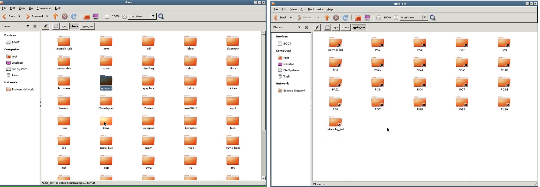
    in "orangepi one"(ubuntu os) there is not gpio folder in sys/class. but i think after run "modprobe gpio-sunxi" built a folder that name is "gpio_sw" and in this folder there are this files: normal_led,pa3,pa6,pa8 and 9,10,13,14,15,21 ,...


  • @Reza Is it too complicated to switch to Debian?


  • @mihai.aldea said:

    Is it too complicated to switch to Debian?

    you told me i change my os ? to armbian ?


  • @Reza
    More info on armbian.com

    I use the debian jessie, works like a charm!


  • @Reza I wouldn't even dream of not using Armbian on OrangePi and NanoPi. Compared to Raspbian it's years ahead in terms of optimization and tidyness. Armbian is the reason I'm avoiding RPi when possible. So go ahead and install a proper OS for your OPi. Not sure if Xenial or Debian, maybe we should wait for @marceloaqno to respond to my comment with the running OS.


  • @Tag
    i worked with armbiam before. but my question is with armbian my problem is resolve ?


  • That I can not say.


  • @Tag said:

    I use the debian jessie, works like a charm!

    ok i change my os and test again. thank you


  • I confirm it's not working on the OPi PC where TMRh20 works.


  • @marceloaqno said:

    @Tag Oops, did I get it right this time (I reuploaded the image)?

    Got it spot on!! looks great!


  • i have problem with compile source domoticz(i must use source domoticz for my changes) in armbian, so i have to use ubuntu.
    @marceloaqno can you help me to run mysensors gateway in orangepi one (ubuntu os).thank you


  • Hi All,

    I put together the steps to get MySensors running on the OrangePi Zero:
    Take note of the SPI part, 1 typo and you will not see /dev/spidev1.0

    sudo apt-get update
    sudo apt-get install sunxi-tools
    
    • How to add /dev/spidev1.0 (which is required since /dev/spidev0.0 is used for the onboard NAND flash)
    cd /boot
    bin2fex /boot/script.bin /root/myscript.txt
    

    Now edit /root/myscript.bin and add/change the following so it looks exactly like the part below:

    [spi0]
    spi_used = 1
    spi_cs_bitmap = 1
    spi_mosi = port:PC00<3><default><default><default>
    spi_miso = port:PC01<3><default><default><default>
    spi_sclk = port:PC02<3><default><default><default>
    spi_cs0 = port:PC03<3><1><default><default>
    	
    [spi1]
    spi_used = 1
    spi_cs_bitmap = 1
    spi_cs0 = port:PA13<2><1><default><default>
    spi_sclk = port:PA14<2><default><default><default>
    spi_mosi = port:PA15<2><default><default><default>
    spi_miso = port:PA16<2><default><default><default>
    	
    [spi_devices]
    spi_dev_num = 2
    	
    [spi_board0]
    modalias = "spidev"
    max_speed_hz = 33000000
    bus_num = 0
    chip_select = 0
    mode = 0
    full_duplex = 1
    manual_cs = 0
    	
    [spi_board1]
    modalias = "spidev"
    max_speed_hz = 33000000
    bus_num = 1
    chip_select = 0
    mode = 0
    full_duplex = 1
    manual_cs = 0
    
    • Then recompile the script file:
    fex2bin /root/myscript.txt /boot/script.bin
    

    Reboot the system

    reboot
    

    2 device files should exist now:

    root@orangepizero:~# ls -l /dev/spi*
    crw------- 1 root root 153, 0 Jan 11 16:31 /dev/spidev0.0
    crw------- 1 root root 153, 1 Jan 11 16:31 /dev/spidev1.0
    

    Load the gpio module

    modprobe gpio-sunxi
    

    To load the module gpio-sunxi automagically load at boot time, add gpio-sunxi to /etc/modules

    echo gpio-sunxi >> /etc/modules
    
    • Now it is time to install the GW.
    cd /root
    git clone https://github.com/marceloaqno/MySensors.git orangepi 
    cd orangepi/ 
    git pull origin spidev
    ./configure --spi-spidev-device=/dev/spidev1.0
    make
    

    Working like a charm!

    If you tested "/bin/mysgw -d" and all works as expected, make the installation permanent:

    make install
    

    Additional
    If you want to read data into a controller using a device file (i.e Mycontroller) use the build string below

     ./configure --spi-spidev-device=/dev/spidev1.0  --my-gateway=serial --my-serial-is-pty --my-serial-pty=/dev/ttyMySensorsGateway
    

    Hope this helps!! have fun!!


  • Code Contributor

    @Tag great! Thanks for the detailed explanation ๐Ÿ‘
    I will add to the instructions page


  • out of curiousity: this all relates to 3.x kernel in armbian right? which has proprietary stuff in there?

    i read somewhere that mainline 4.10 SPI is "work in progress"


  • @pansen
    Yes correct, for OPI Zero only ARMbian 3.x is available as a download image.
    I used the debian jessie one


  • Code Contributor

    Instructions page updated, let me know if there is any mistake.


  • @marceloaqno

    looks great!! thx!!๐Ÿ‘


  • Excellent work !!! It finally works, I believe the slight mistake was with the damn SPI device ID. Now that I've enabled /dev/spidev1.0 everything works perfect. Really nice job and awesome commitment to showing people that it's time for them to pull their heads out of their a.... and spend less for way more awesome boards because let's face it, RPi has the greatest community support but it's a nothing more than an expensive closed source crappy board.


  • @mihai.aldea
    Great!!, found out the SPI0 is used for the NAND flash, once you add SPI1 to the script.bin, also the need board paragraph with bus 1 needs to be added otherwise it will not work.... anyway great you got mysensors up and running!!
    About the RPI, i like both boards, and in my opinion the enormous success of the RPI is responsible, for the large collection of OPI boards that is available these days ๐Ÿ˜‰


  • There are few who know that lots of asian compaines were producing SBC's long before RPi ever existed. RPi has to take credit for the SBC boom, but the connaisseurs will always prefer a top notch SBC that costs less than half of an RPi and is piled with features. Take the OPi Zero for instance, it's way smaller than RPi 3, has half the RAM and doesn't have Bluetooth. But you can buy 4 OPi Zeros with the money you'd spend on an RPi 3.
    Anyway it's an endless debate here, I'm just glad I could help a bit bringing this to life, even though you and @marceloaqno did the heavy lifting.


  • Hardware Contributor

    Thank you for the hard work guys, I have a fresh orange pi zero and I will install armbian and try this hack as soon as possible. Looks like a great way to have an ultra compact&cheap controller + gateway system !


  • Code Contributor

    Support for OrangePi is now part of the official MySensors development repository.
    In the official version, it is necessary to define the CE and CS pins, as the default ones will not work. This will change in the future, but more work needs to be done to better detect the different types of Orange Pi and other H3 soc boards.
    For now, if you have set your system in the same way as the wiring instructions, use:

    ./configure --spi-spidev-device=/dev/spidev1.0 --my-transport=nrf24 --my-rf24-ce-pin=2 --my-rf24-cs-pin=13


  • @marceloaqno

    Thank you for your hard work and continued support on this!!


  • @mihai.aldea
    It's working on my OPi One with Armbian. MySensors and TMRh20 works!

    Only in ./MySensors: bin
    Only in ./MySensors: build
    diff -ruBdX ex ./_MySensors/drivers/RF24/RF24.cpp ./MySensors/drivers/RF24/RF24.cpp
    --- ./_MySensors/drivers/RF24/RF24.cpp<>2017-01-28 10:24:03.557215399 +0200
    +++ ./MySensors/drivers/RF24/RF24.cpp<->2017-01-28 10:58:51.757543157 +0200
    @@ -29,7 +29,7 @@
     LOCAL RF24_receiveCallbackType RF24_receiveCallback = NULL;
     #endif
    .
    -#ifdef LINUX_SPI_BCM
    +#if defined (LINUX_SPI_BCM) || (LINUX_SPI_SPIDEV)
     uint8_t spi_rxbuff[32+1] ; //SPI receive buffer (payload max 32 bytes)
     uint8_t spi_txbuff[32+1] ; //SPI transmit buffer (payload max 32 bytes + 1 byte for the command)
     #endif
    @@ -56,7 +56,7 @@
     <----->RF24_csn(LOW);
     <----->// timing
     <----->delayMicroseconds(10);
    -#ifdef LINUX_SPI_BCM
    +#if defined (LINUX_SPI_BCM) || (LINUX_SPI_SPIDEV)
     <----->uint8_t * prx = spi_rxbuff;
     <----->uint8_t * ptx = spi_txbuff;
     <----->uint8_t size = len + 1; // Add register value to transmit buffer
    diff -ruBdX ex ./_MySensors/Makefile.inc ./MySensors/Makefile.inc
    --- ./_MySensors/Makefile.inc<->2017-01-28 10:49:53.990638008 +0200
    +++ ./MySensors/Makefile.inc<-->2017-01-28 11:12:57.601198157 +0200
    @@ -1,5 +1,5 @@
     SOC=H3
    -CPPFLAGS=-march=armv7-a -mtune=cortex-a7 -mfpu=neon-vfpv4 -mfloat-abi=hard -DMY_RADIO_NRF24 -DMY_GATEWAY_LINUX -DMY_DEBUG -DLINUX_SPI_SPIDEV.
    +CPPFLAGS=-march=armv7-a -mtune=cortex-a7 -mfpu=neon-vfpv4 -mfloat-abi=hard -DMY_RADIO_NRF24 -DMY_GATEWAY_LINUX -DLINUX_SPI_SPIDEV -DMY_RF24_CE_PIN=7 -DSPI_S
     LDFLAGS=-pthread.
     PREFIX=/usr/local
     CC=gcc


  • Hi all

    I want to give feedback here.

    Today i tried to build a orange pi gateway with a connected usb - rs485 converter on it. And what should I say - It worked without problems. Many thanks to you all ๐Ÿ™‚
    Great


  • Hi to all, I don't know if this is the right thread, but I'm trying to use an odroid c1 as a gateway. I'm posting here because I think you all could help me.
    The original thread I have done is this one
    https://forum.mysensors.org/topic/6083/odroid-c1-as-getaway
    Feel free to go over there and give me advises.


Log in to reply
 

Suggested Topics

0
Online

11.2k
Users

11.1k
Topics

112.5k
Posts