i need a change in transport serial gateway
-
hi friends
in my wireless network all of configure and sketch is ok . even i use repeater between nodes.but i have error and lost some of command or ack . % of error is much. i want decrease this errors.even if delay will increase (a little).
i search about this and i found some things.
i think if i change MY_BAUD_RATE in MYConfig and decrease this , so decrease % of errors. is this true ?
also if i put a delay between send and receive command and ack , so this may be effective !
also if i increase number of resend command or ack (when first or second was fail) may be effective !
are these true ? if yes , i dont know how change this ! :( please help me for the most Reliabilitythank you
@Reza Sorry to hear you are still having trouble with your nodes communication. I haven't tried any of the things you have outlined above but it will cost you nothing to try so worth a go.
A couple of other things you might like to try( if you haven't already)
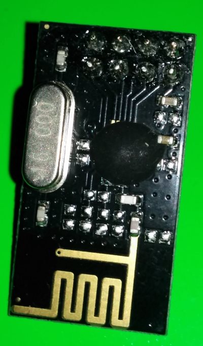
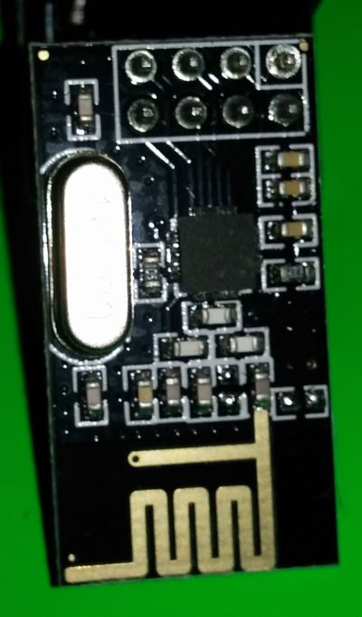
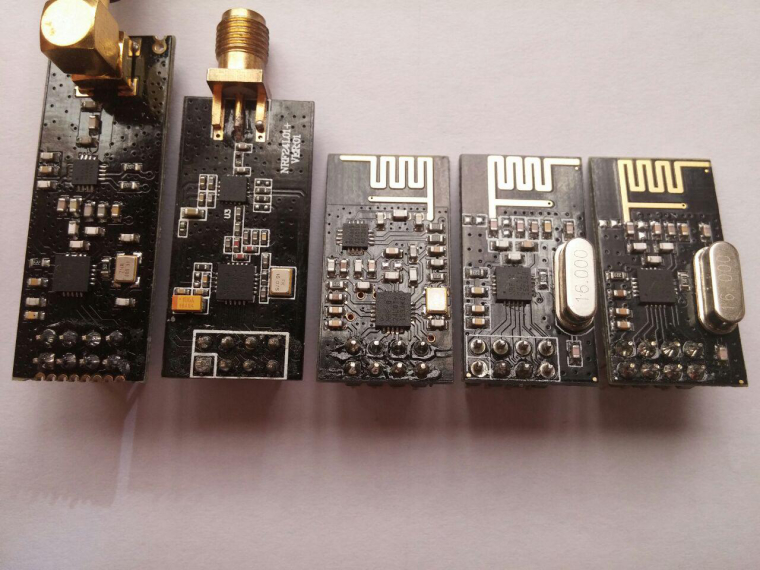
First have you tried different NRF modules. I have had some of the blob type that were no good at all and very unreliable.
They are easy to spot see the first picture has a round blob where the normally square chip is, as can be seen on the second picture. If yours are the round blob type that may be the problem
The second thing would be to run a scanner to see if you have some congestion on the channel you are using.
To do this you will need a spare arduino and nrf radio
First install the rf24 library from your library manager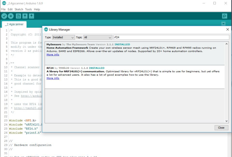
then you will need to load the scanner sketch from maniacbug to your arduino. I have made a slight change to this sketch so it will use the same wiring as MySensors does.
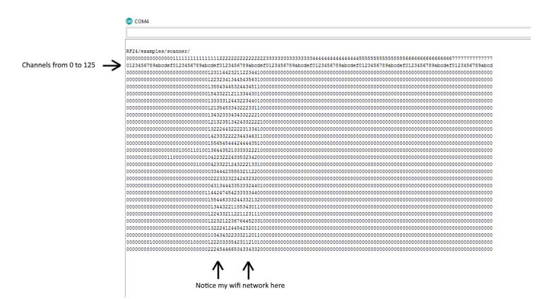
/*
 Copyright (C) 2011 J. Coliz <maniacbug@ymail.com>

 This program is free software; you can redistribute it and/or
 modify it under the terms of the GNU General Public License
 version 2 as published by the Free Software Foundation.
 */

/**
 * Channel scanner
 *
 * Example to detect interference on the various channels available.
 * This is a good diagnostic tool to check whether you're picking a
 * good channel for your application.
 *
 * Inspired by cpixip.
 * See http://arduino.cc/forum/index.php/topic,54795.0.html
 *
 * uses the RF24 library. install from the library manager or download from
 * http://tmrh20.github.io/RF24/index.html for a manual install
 */

#include <SPI.h>
#include "nRF24L01.h"
#include "RF24.h"
#include "printf.h"

//
// Hardware configuration
//

// Set up nRF24L01 radio on SPI bus plus pins 9 & 10

RF24 radio(9,10);

//
// Channel info
//

const uint8_t num_channels = 126;
uint8_t values[num_channels];

//
// Setup
//

void setup(void)
{
  //
  // Print preamble
  //

  Serial.begin(115200);
  printf_begin();
  Serial.println(F("\n\rRF24/examples/scanner/"));

  //
  // Setup and configure rf radio
  //

  radio.begin();
  radio.setAutoAck(false);

  // Get into standby mode
  radio.startListening();
  radio.stopListening();

  // Print out header, high then low digit
  int i = 0;
  while ( i < num_channels )
  {
    printf("%x",i>>4);
    ++i;
  }
  Serial.println();
  i = 0;
  while ( i < num_channels )
  {
    printf("%x",i&0xf);
    ++i;
  }
  Serial.println();


}

//
// Loop
//

const int num_reps = 100;

void loop(void)
{
  // Clear measurement values
  memset(values,0,sizeof(values));

  // Scan all channels num_reps times
  int rep_counter = num_reps;
  while (rep_counter--)
  {
    int i = num_channels;
    while (i--)
    {
      // Select this channel
      radio.setChannel(i);

      // Listen for a little
      radio.startListening();
      delayMicroseconds(225);


      // Did we get a carrier?
      if ( radio.testCarrier() ){
        ++values[i];
      }
      radio.stopListening();
    }
  }

  // Print out channel measurements, clamped to a single hex digit
  int i = 0;
  while ( i < num_channels )
  {
    printf("%x",min(0xf,values[i]&0xf));
    ++i;
  }
  Serial.println();
}

// vim:ai:cin:sts=2 sw=2 ft=cpp
Once it has loaded open up your serial monitor and you will see a sort of waterfall display that represents the 126 channels of the nrf module. A new line will be added every few seconds as the scanning progresses.
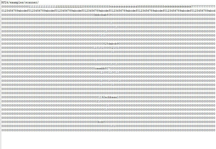
The channels with 0 mean there is no activity. Channels with higher numbers mean there is traffic on those channels. The higher the number the more busy that channel is.You can see on the sample below most of my channels are pretty clear (I am lucky, I live in a semi rural area) There is activity around channels 30 to 40, that is my wifi network.
-
@Reza Sorry to hear you are still having trouble with your nodes communication. I haven't tried any of the things you have outlined above but it will cost you nothing to try so worth a go.
A couple of other things you might like to try( if you haven't already)
First have you tried different NRF modules. I have had some of the blob type that were no good at all and very unreliable.
They are easy to spot see the first picture has a round blob where the normally square chip is, as can be seen on the second picture. If yours are the round blob type that may be the problem
The second thing would be to run a scanner to see if you have some congestion on the channel you are using.
To do this you will need a spare arduino and nrf radio
First install the rf24 library from your library managerthen you will need to load the scanner sketch from maniacbug to your arduino. I have made a slight change to this sketch so it will use the same wiring as MySensors does.
/*
 Copyright (C) 2011 J. Coliz <maniacbug@ymail.com>

 This program is free software; you can redistribute it and/or
 modify it under the terms of the GNU General Public License
 version 2 as published by the Free Software Foundation.
 */

/**
 * Channel scanner
 *
 * Example to detect interference on the various channels available.
 * This is a good diagnostic tool to check whether you're picking a
 * good channel for your application.
 *
 * Inspired by cpixip.
 * See http://arduino.cc/forum/index.php/topic,54795.0.html
 *
 * uses the RF24 library. install from the library manager or download from
 * http://tmrh20.github.io/RF24/index.html for a manual install
 */

#include <SPI.h>
#include "nRF24L01.h"
#include "RF24.h"
#include "printf.h"

//
// Hardware configuration
//

// Set up nRF24L01 radio on SPI bus plus pins 9 & 10

RF24 radio(9,10);

//
// Channel info
//

const uint8_t num_channels = 126;
uint8_t values[num_channels];

//
// Setup
//

void setup(void)
{
  //
  // Print preamble
  //

  Serial.begin(115200);
  printf_begin();
  Serial.println(F("\n\rRF24/examples/scanner/"));

  //
  // Setup and configure rf radio
  //

  radio.begin();
  radio.setAutoAck(false);

  // Get into standby mode
  radio.startListening();
  radio.stopListening();

  // Print out header, high then low digit
  int i = 0;
  while ( i < num_channels )
  {
    printf("%x",i>>4);
    ++i;
  }
  Serial.println();
  i = 0;
  while ( i < num_channels )
  {
    printf("%x",i&0xf);
    ++i;
  }
  Serial.println();


}

//
// Loop
//

const int num_reps = 100;

void loop(void)
{
  // Clear measurement values
  memset(values,0,sizeof(values));

  // Scan all channels num_reps times
  int rep_counter = num_reps;
  while (rep_counter--)
  {
    int i = num_channels;
    while (i--)
    {
      // Select this channel
      radio.setChannel(i);

      // Listen for a little
      radio.startListening();
      delayMicroseconds(225);


      // Did we get a carrier?
      if ( radio.testCarrier() ){
        ++values[i];
      }
      radio.stopListening();
    }
  }

  // Print out channel measurements, clamped to a single hex digit
  int i = 0;
  while ( i < num_channels )
  {
    printf("%x",min(0xf,values[i]&0xf));
    ++i;
  }
  Serial.println();
}

// vim:ai:cin:sts=2 sw=2 ft=cpp
Once it has loaded open up your serial monitor and you will see a sort of waterfall display that represents the 126 channels of the nrf module. A new line will be added every few seconds as the scanning progresses.
The channels with 0 mean there is no activity. Channels with higher numbers mean there is traffic on those channels. The higher the number the more busy that channel is.You can see on the sample below most of my channels are pretty clear (I am lucky, I live in a semi rural area) There is activity around channels 30 to 40, that is my wifi network.
@Boots33
first thank you for your code. this is very interesting.
so i test this in my home and my friends home.
first pic is test near controller (but now controller is off)
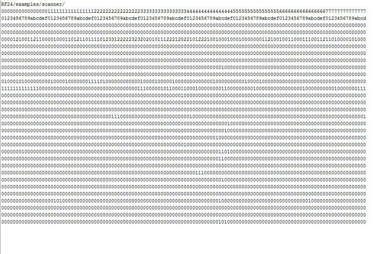
2th pic is test near a relay node(that very bad working)
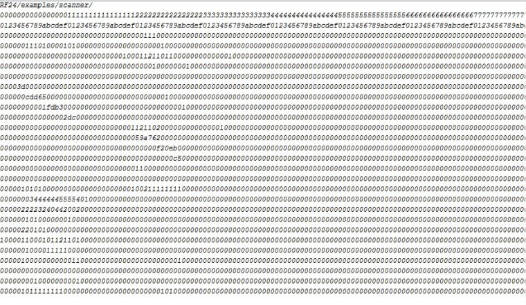
3th is in my friend house ...
-
@Reza Sorry to hear you are still having trouble with your nodes communication. I haven't tried any of the things you have outlined above but it will cost you nothing to try so worth a go.
A couple of other things you might like to try( if you haven't already)
First have you tried different NRF modules. I have had some of the blob type that were no good at all and very unreliable.
They are easy to spot see the first picture has a round blob where the normally square chip is, as can be seen on the second picture. If yours are the round blob type that may be the problem
The second thing would be to run a scanner to see if you have some congestion on the channel you are using.
To do this you will need a spare arduino and nrf radio
First install the rf24 library from your library managerthen you will need to load the scanner sketch from maniacbug to your arduino. I have made a slight change to this sketch so it will use the same wiring as MySensors does.
/*
 Copyright (C) 2011 J. Coliz <maniacbug@ymail.com>

 This program is free software; you can redistribute it and/or
 modify it under the terms of the GNU General Public License
 version 2 as published by the Free Software Foundation.
 */

/**
 * Channel scanner
 *
 * Example to detect interference on the various channels available.
 * This is a good diagnostic tool to check whether you're picking a
 * good channel for your application.
 *
 * Inspired by cpixip.
 * See http://arduino.cc/forum/index.php/topic,54795.0.html
 *
 * uses the RF24 library. install from the library manager or download from
 * http://tmrh20.github.io/RF24/index.html for a manual install
 */

#include <SPI.h>
#include "nRF24L01.h"
#include "RF24.h"
#include "printf.h"

//
// Hardware configuration
//

// Set up nRF24L01 radio on SPI bus plus pins 9 & 10

RF24 radio(9,10);

//
// Channel info
//

const uint8_t num_channels = 126;
uint8_t values[num_channels];

//
// Setup
//

void setup(void)
{
  //
  // Print preamble
  //

  Serial.begin(115200);
  printf_begin();
  Serial.println(F("\n\rRF24/examples/scanner/"));

  //
  // Setup and configure rf radio
  //

  radio.begin();
  radio.setAutoAck(false);

  // Get into standby mode
  radio.startListening();
  radio.stopListening();

  // Print out header, high then low digit
  int i = 0;
  while ( i < num_channels )
  {
    printf("%x",i>>4);
    ++i;
  }
  Serial.println();
  i = 0;
  while ( i < num_channels )
  {
    printf("%x",i&0xf);
    ++i;
  }
  Serial.println();


}

//
// Loop
//

const int num_reps = 100;

void loop(void)
{
  // Clear measurement values
  memset(values,0,sizeof(values));

  // Scan all channels num_reps times
  int rep_counter = num_reps;
  while (rep_counter--)
  {
    int i = num_channels;
    while (i--)
    {
      // Select this channel
      radio.setChannel(i);

      // Listen for a little
      radio.startListening();
      delayMicroseconds(225);


      // Did we get a carrier?
      if ( radio.testCarrier() ){
        ++values[i];
      }
      radio.stopListening();
    }
  }

  // Print out channel measurements, clamped to a single hex digit
  int i = 0;
  while ( i < num_channels )
  {
    printf("%x",min(0xf,values[i]&0xf));
    ++i;
  }
  Serial.println();
}

// vim:ai:cin:sts=2 sw=2 ft=cpp
Once it has loaded open up your serial monitor and you will see a sort of waterfall display that represents the 126 channels of the nrf module. A new line will be added every few seconds as the scanning progresses.
The channels with 0 mean there is no activity. Channels with higher numbers mean there is traffic on those channels. The higher the number the more busy that channel is.You can see on the sample below most of my channels are pretty clear (I am lucky, I live in a semi rural area) There is activity around channels 30 to 40, that is my wifi network.
@Boots33
channel 0 and 76 that i use and test seem not busy and my problem is not related to this .
as I said before . i think this is not related to my hardware because i use several .
i test 5 model radio. also i test LED instead of relay but i have % of error (much).
use power 5v 10A use radio adapter.use reglator .... but ...
so i think best of solution is little change in library.do you think with decrease boud rate or increase number of resend or increase delay between command and ack can resolve this issue ?
Hello! It looks like you're interested in this conversation, but you don't have an account yet.
Getting fed up of having to scroll through the same posts each visit? When you register for an account, you'll always come back to exactly where you were before, and choose to be notified of new replies (either via email, or push notification). You'll also be able to save bookmarks and upvote posts to show your appreciation to other community members.
With your input, this post could be even better 💗
Register Login