US decora style wall switch
-
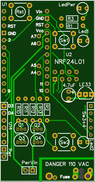
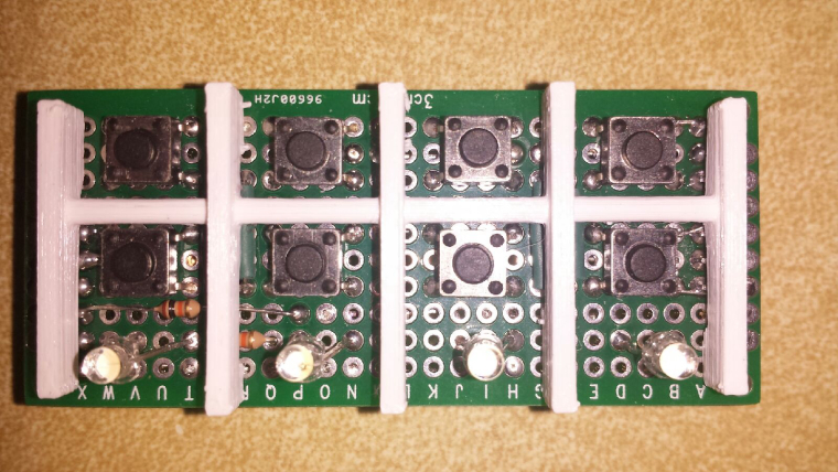
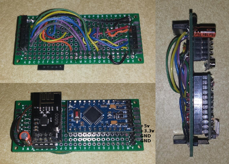
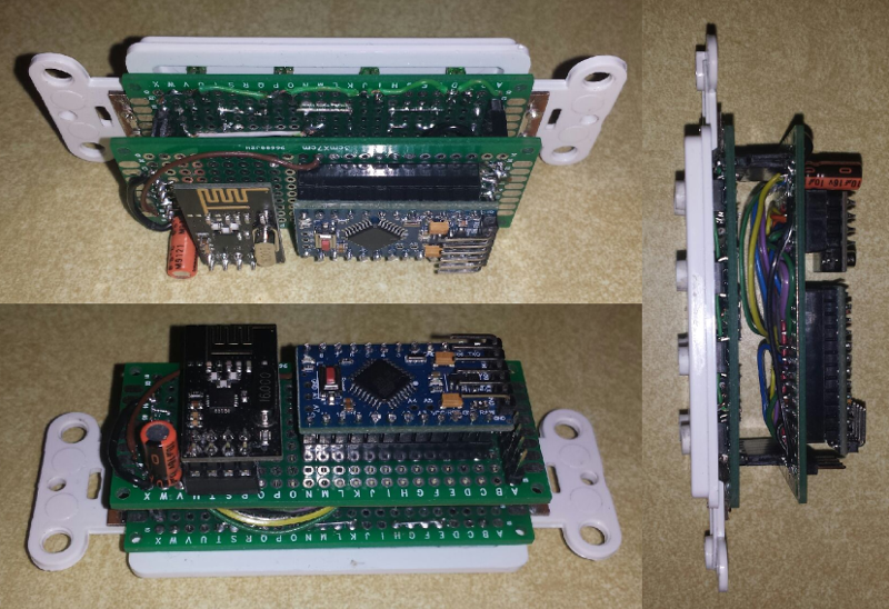
So here is my latest update. I now have the controller board made that the switch board will stack on to. It currently uses all analog and digital pins of the pro mini except pins A4, A5, A6 and A7 which are not in the standard header rows. This is the board as it is right now.
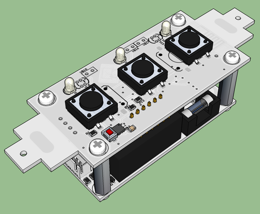
And this is the controller board stacked with the switch board.
I wrote a simple sketch to test the keypad which is just a 2x4 matrix. One thing that I realized that I forgot which I will fix in the next couple days is the current limiting resistors for the 4 LEDs.
For testing until I figure out the design of the power supply board, I am just powering this using the supply from my UNO as it has both the 3.3 and 5 volt outputs.
My plan for now is to use each row as an OFF and an ON button with a corresponding status LED, but the possibilities for this are much greater. This could be used as a controller for 8 individual scenes, bright/dim controls, or whatever you can think of. This could be used to talk directly to other nodes for lighting control or any number of things. You could build other switch boards for this that would maybe contain more switches (eliminating the LEDs of course), or any number of combinations of switches and sensors.
The final setup is going to be quite bulky and will need a deep US wall box to fit everything, and even that might be tight. For now this is a proof of concept design to test the feasibility of this as a controller. Eventually if things work out, I may seek help from the forum to create a dedicated PCB for this which could be stacked into a smaller package.
I welcome any thoughts, comments and feedback on this design.
I'm currently working on the following PCB design for US Decora Wall Plate.
It's designed to have some components/ connections on the back, but most of the components on the front of the PCB.
It has provisions for connecting:
4 x Switch (A0, A1, A2, A3)
4 x LED (A4, A5, A6, A7)
4 x Relay/SSR (D5, D6, D7, D8 connected to NPN transistor)
2 x sensor (pin D3 and D4)Designed for using an Arduino Pro Mini 5V with A4 to A7
I can share the gerbers once completed
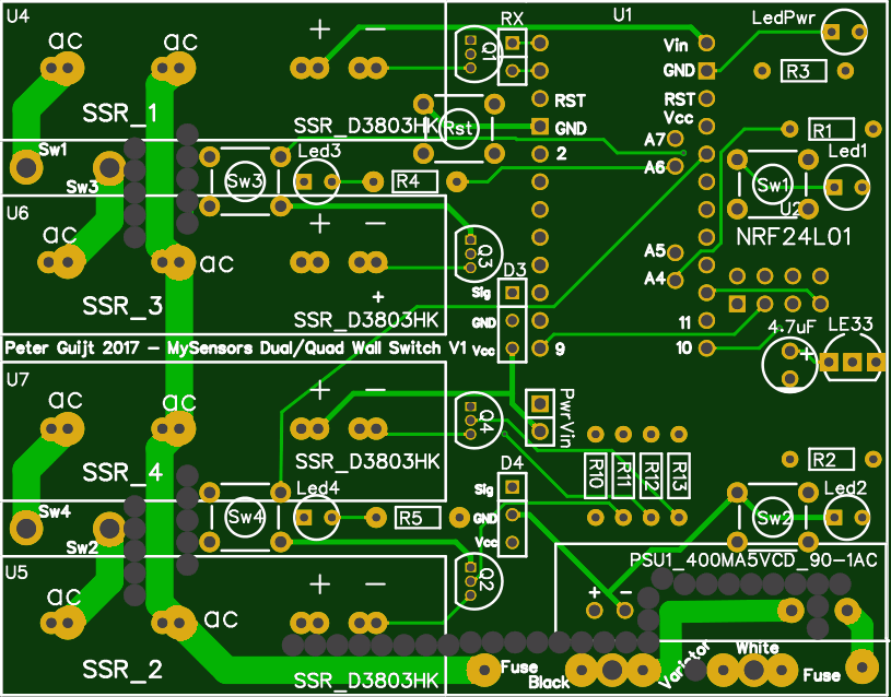
I'm also working on a Dual Decora style wall plate switch containing 4 x 8Amp SSR
-
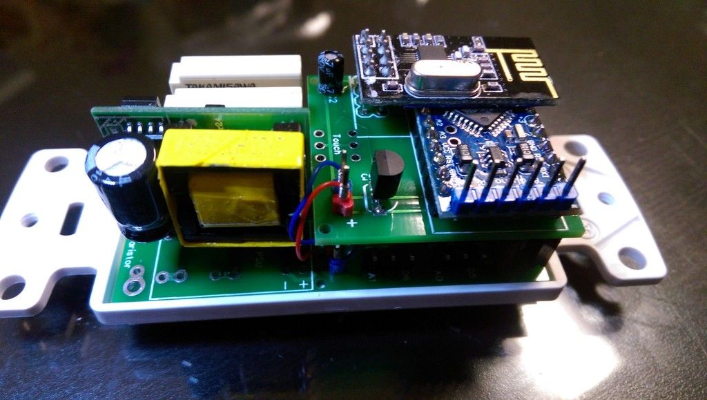
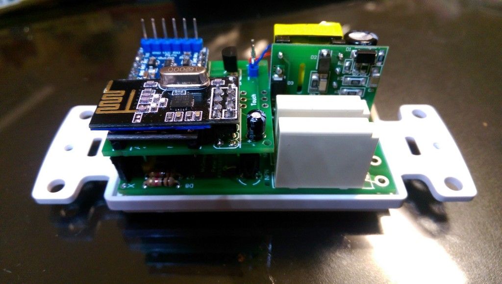
Very interesting designs @enterprised and @dbemowsk. I've also been working on my own version of decora switch and relay system. It's designed to use empty keystone switch plates with 1, 2, or 3 switches and uses keystone jack fillers as the switch covers so they look almost commercial. It's a 3 PCB system. The front PCB has the switches, LED's, reset button, CPU, and an RFM69 or NRF radio. The middle PCB has a MeanWell IRM-02 or HLK AC->DC converter (with fuse, thermal fuse, and varistor), a replaceable fused 10A AC relay with opto-coupler isolation, 5V and 3.3V rails and a 2 wire temperature probe to measure the temp of the PSU module. The back PCB is just a cover to insure no sharp solder points are in an electrical box. I decided that since this will be in my walls, I would only use name brand parts (from digikey and mouser) on the high voltage side which increases costs but should reduce the risk of fire (or at least make me feel better).
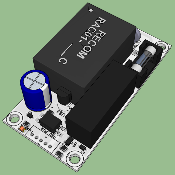
I've designed the PCB and checked them over but we're in the middle of buying a house and moving so I haven't ordered any yet. Here's the 3D rendering of the PSU and CPU boards together and a one of the PSU board.
-
I'm currently working on the following PCB design for US Decora Wall Plate.
It's designed to have some components/ connections on the back, but most of the components on the front of the PCB.
It has provisions for connecting:
4 x Switch (A0, A1, A2, A3)
4 x LED (A4, A5, A6, A7)
4 x Relay/SSR (D5, D6, D7, D8 connected to NPN transistor)
2 x sensor (pin D3 and D4)Designed for using an Arduino Pro Mini 5V with A4 to A7
I can share the gerbers once completed
I'm also working on a Dual Decora style wall plate switch containing 4 x 8Amp SSR
@enterprised For my design, I am hoping to use an HLK-PM01 power supply. Comparing to the one you have listed it has a few advantages:
- Enclosed components vs exposed components on yours
- Continuous output current of 600mA vs 200mA on yours
- 50mV or less of ripple on the output vs 100mA on yours
Having the components sealed will protect more against short circuits on the high voltage side. As for the current, I probably wouldn't need 600mA, but using a supply that is rated a bit higher I figure will be less stress on the components and cut down on heat. Plus I have to do 3.3 volt regulation for the radio, so I figure I am covered for that too. And last, the better the ripple on the output, the less filtering that will be needed for a more stable radio.
The other thing that I like about my design is that it is modular. You would be able to have a number of different switches, sensors or LEDs as the faceplate while having one arduino/radio board and one power supply board. As mentioned in one of my previous posts, the current design is a bit bulky, but with a better PCB design, I think I can compress the layers quite a bit more. Looking at your pics, yours looks like a nice design too.
-
Very interesting designs @enterprised and @dbemowsk. I've also been working on my own version of decora switch and relay system. It's designed to use empty keystone switch plates with 1, 2, or 3 switches and uses keystone jack fillers as the switch covers so they look almost commercial. It's a 3 PCB system. The front PCB has the switches, LED's, reset button, CPU, and an RFM69 or NRF radio. The middle PCB has a MeanWell IRM-02 or HLK AC->DC converter (with fuse, thermal fuse, and varistor), a replaceable fused 10A AC relay with opto-coupler isolation, 5V and 3.3V rails and a 2 wire temperature probe to measure the temp of the PSU module. The back PCB is just a cover to insure no sharp solder points are in an electrical box. I decided that since this will be in my walls, I would only use name brand parts (from digikey and mouser) on the high voltage side which increases costs but should reduce the risk of fire (or at least make me feel better).
I've designed the PCB and checked them over but we're in the middle of buying a house and moving so I haven't ordered any yet. Here's the 3D rendering of the PSU and CPU boards together and a one of the PSU board.
@TD22057 Excellent design. I like the fact that you used the Recom PSU. I have used the Recom ones and they are very well built, but they are slightly larger than the HLK-PM01s. The price is a bit higher too, but I figured for what mine would be doing, the HLK-PM01 will be sufficient. I plan to also use a thermal fuse with an MOV and fuse for good protection. Mine at this point is a bit bulky to fit relays in right now, but it would work well for a nice scene controller node or a direct control for another node.
-
@enterprised For my design, I am hoping to use an HLK-PM01 power supply. Comparing to the one you have listed it has a few advantages:
- Enclosed components vs exposed components on yours
- Continuous output current of 600mA vs 200mA on yours
- 50mV or less of ripple on the output vs 100mA on yours
Having the components sealed will protect more against short circuits on the high voltage side. As for the current, I probably wouldn't need 600mA, but using a supply that is rated a bit higher I figure will be less stress on the components and cut down on heat. Plus I have to do 3.3 volt regulation for the radio, so I figure I am covered for that too. And last, the better the ripple on the output, the less filtering that will be needed for a more stable radio.
The other thing that I like about my design is that it is modular. You would be able to have a number of different switches, sensors or LEDs as the faceplate while having one arduino/radio board and one power supply board. As mentioned in one of my previous posts, the current design is a bit bulky, but with a better PCB design, I think I can compress the layers quite a bit more. Looking at your pics, yours looks like a nice design too.
Oops, attached the wrong link.
I'm using the 400ma version of this PSU. The design uses 200ma max with 4 switches/LED's/SSR's, so plenty of overhead. I actually stepped away from the HLK-PM01 due to the very poor reliability of these modules, too many that failed within a few months.
I use an LE33 in TO92 package to create and regulate the 3.3v for the radio
The ripple is a non issue as I have 7 module of the previous design installed and working around the house.
I'm enclosing the entire module with a hot vacuum formed custom enclosure, so the entire circuit is fully protected. Amazing what you can do with a sheet of plastic, some wood, vacuum cleaner and a oven.
My design is also using multiple PCB's. There is a second PCB sitting on top containing 2 SSR's and related components
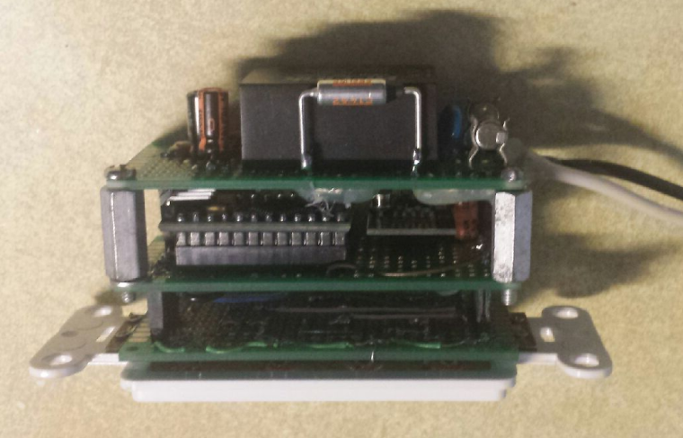
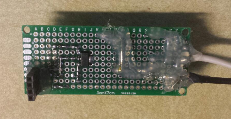
This was my previous design using relays not SSR but all other components are the same.
-
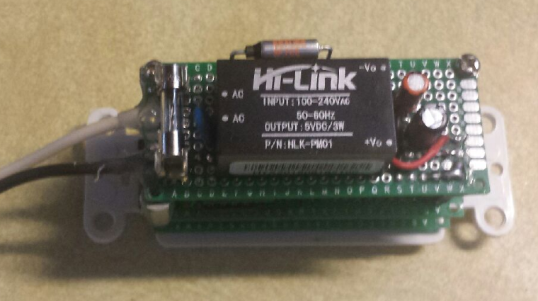
So for my latest update on this, I have finished the power supply board. One thing I learned in making this that I didn't even think of at first was that when I soldered on the thermal relay, the heat from the soldering was enough to blow the relay. Thus, my initial test did not work. I was finally able to get a fuse installed and working. I would have preferred it to be more centered on the side of the Hi-Link module, but I am thinking that it should still be effective.
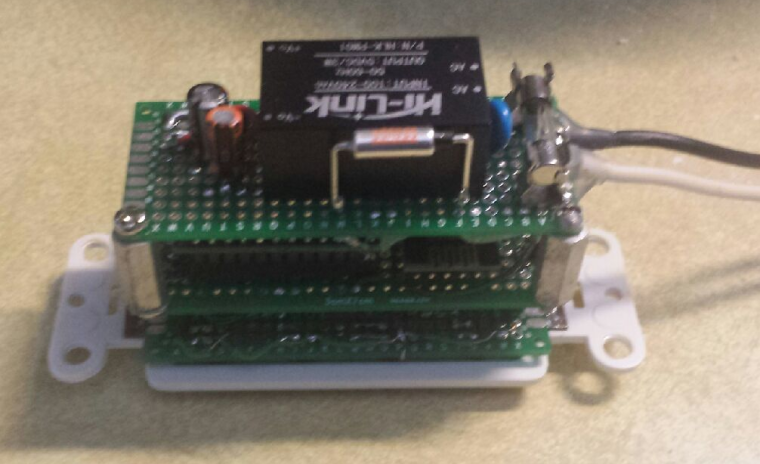
On the bottom side of the board you can see the LM1117 3.3v regulator. For the high voltage side, I have hot glue over all traces for safety in testing.
I used a 22uf cap on the 5 volt output and a 10uf cap on the 3.3 volt output. I have also added hot glue to the incoming hot and neutral leads to provide some strain relief on the wire as it attaches to the board.
The last thing I want to do is fabricate a plastic cover to put over everything that will fit into the wall box. I think I am going to need a deep wall box to house the connections and the module.
I did connect this and have it paired with my Vera. Each row is OFF, ON and status LED to indicate the ON state. I have debated on having the LED on when the switch is off to give better visibility to the switch when it is dark. In Vera, I can tie the switches to devices using scenes.
Overall, this proof of concept design is working well.
Vera Plus running UI7 with MySensors, Sonoffs and 1-Wire devices
Visit my website for more Bits, Bytes and Ramblings from me: http://dan.bemowski.info/ -
So for my latest update on this, I have finished the power supply board. One thing I learned in making this that I didn't even think of at first was that when I soldered on the thermal relay, the heat from the soldering was enough to blow the relay. Thus, my initial test did not work. I was finally able to get a fuse installed and working. I would have preferred it to be more centered on the side of the Hi-Link module, but I am thinking that it should still be effective.
On the bottom side of the board you can see the LM1117 3.3v regulator. For the high voltage side, I have hot glue over all traces for safety in testing.
I used a 22uf cap on the 5 volt output and a 10uf cap on the 3.3 volt output. I have also added hot glue to the incoming hot and neutral leads to provide some strain relief on the wire as it attaches to the board.
The last thing I want to do is fabricate a plastic cover to put over everything that will fit into the wall box. I think I am going to need a deep wall box to house the connections and the module.
I did connect this and have it paired with my Vera. Each row is OFF, ON and status LED to indicate the ON state. I have debated on having the LED on when the switch is off to give better visibility to the switch when it is dark. In Vera, I can tie the switches to devices using scenes.
Overall, this proof of concept design is working well.
@dbemowsk
I think that with a little effort the switch and middle PCB can become one in a custom designed PCB. You'll end up with switches and LED's on one side and the Arduino and radio etc on the other side. That's what I did. This will make your design a lot more compact.I used https://easyeda.com/ to design and manufacture my PCB's.
-
So for my latest update on this, I have finished the power supply board. One thing I learned in making this that I didn't even think of at first was that when I soldered on the thermal relay, the heat from the soldering was enough to blow the relay. Thus, my initial test did not work. I was finally able to get a fuse installed and working. I would have preferred it to be more centered on the side of the Hi-Link module, but I am thinking that it should still be effective.
On the bottom side of the board you can see the LM1117 3.3v regulator. For the high voltage side, I have hot glue over all traces for safety in testing.
I used a 22uf cap on the 5 volt output and a 10uf cap on the 3.3 volt output. I have also added hot glue to the incoming hot and neutral leads to provide some strain relief on the wire as it attaches to the board.
The last thing I want to do is fabricate a plastic cover to put over everything that will fit into the wall box. I think I am going to need a deep wall box to house the connections and the module.
I did connect this and have it paired with my Vera. Each row is OFF, ON and status LED to indicate the ON state. I have debated on having the LED on when the switch is off to give better visibility to the switch when it is dark. In Vera, I can tie the switches to devices using scenes.
Overall, this proof of concept design is working well.
@dbemowsk - Nice work!
Here is a discussion and more links about safety in designing a PCB with AC power that might come in handy:
https://forum.mysensors.org/topic/4175/clearance-creepage-and-other-safety-aspects-in-mysensors-pcbs.Also if you dont want to completley redesign a PCB you can take some of my designs and redesign them to your purpose.
-
So I have had my prototype version of this switch installed for a few weeks now and it seems to be performing well with my Vera setup. This week I added a new tool to my arsenal. I purchased an Anet A8 3D printer kit. I just got it put together yesterday. I ordered a roll of ABS which came yesterday. It was supposed to be white, but they sent transparent (Grrrr....). Trying to work with the ebay seller on this.
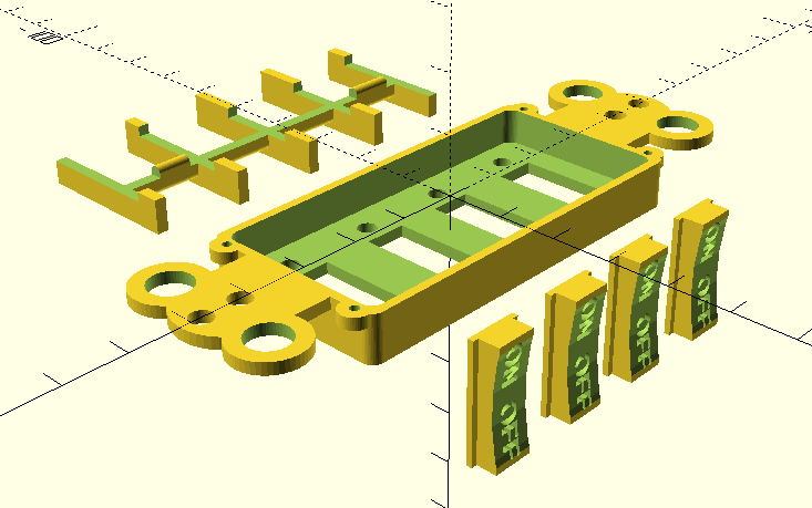
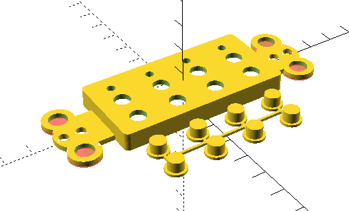
Anyway, I wanted a project to try that would be useful, but not super difficult. I decided to build a better switch plate to improve my prototype of this switch. I knew that one of the big places to go for 3D stuff to print was thingiverse.com. I did a search on the site and someone had a 3d file for a decora blank wall plate. I decided to download the files and see what I could do. I had never done anything in any kind of CAD program, but thought, how bad can it be. I ended up finding OpenSCAD. Drawing objects in the software is done much like a structured programming language. Within a day of teaching myself some things in it, I came up with this:
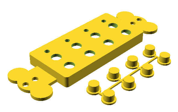
I have not printed this yet since I am still trying to resolve my filament issue with the ebay seller,. but as soon as I get that figured out, I will give this a test. Before printing I may still look at adding some reliefs in the 4 corner tabs to save at least a little bit of plastic, but overall I think it looks good. I'll post more here as I get it done.
-
Looking forward to pictures :) Keep up the good work!
-
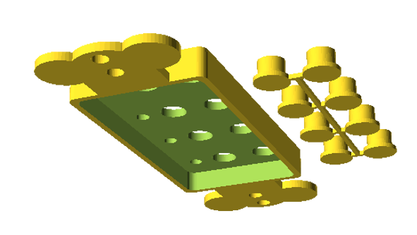
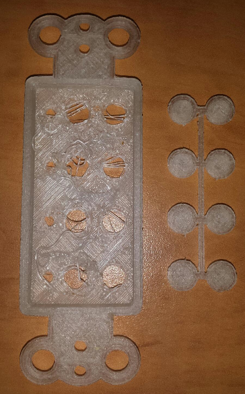
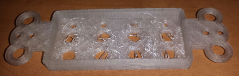
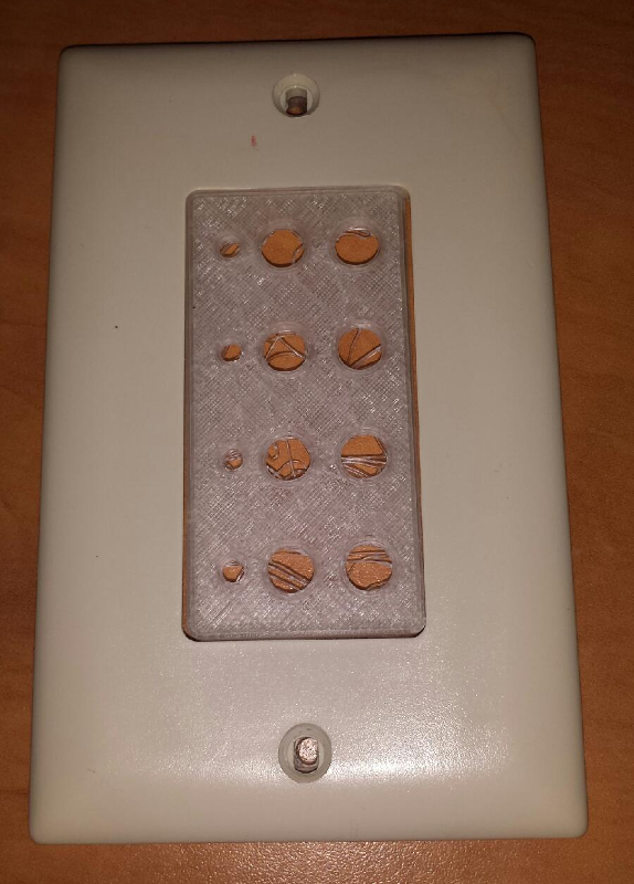
So even though I only have transparent ABS to work with at the moment, I decided to do a test print of this (I actually did 2 test prints). The results were in my eyes only fair. Though the outside didn't look bad, the inside is a bit messy. I think I could clean it up and make it usable, but I think it could be better. I printed it with the ears down and the face up. The print may come out better if I print it with the face down. The ears may be a little stringy, but that is a little less of an issue because the ears are hidden by the faceplate. I had to increase the hole size in the face where the buttons come through for the buttons to fit (this was the reason for the second test print). With the first print, the buttons were a little snug in the holes.
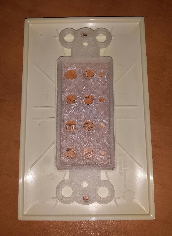
Without further ado, here are the pics:
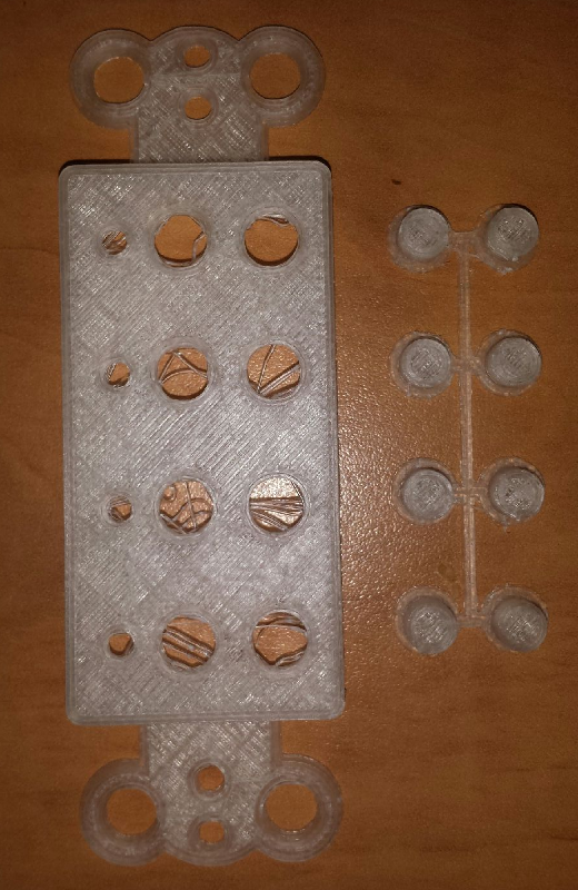
These two pics show how it fits in the faceplate.
-
If anyone is interested, I posted the 3D design files for this switch plate out on thingiverse.com. Included is the OpenSCAD file and .stl files for making modifications if you'd like.
http://www.thingiverse.com/thing:2136094Enjoy...
-
I think this 3D printer is going to help a lot with my HA hobby. Now I will be able to make custom enclosures and things and not have to search the web to say, "ehh, that will kinda fit". I just have to get used to using OpenSCAD.
@dbemowsk said in US decora style wall switch:
I think this 3D printer is going to help a lot with my HA hobby. Now I will be able to make custom enclosures and things and not have to search the web to say, "ehh, that will kinda fit". I just have to get used to using OpenSCAD.
You should give FreeCAD a shot. Open source and runs on Windows, macOS and Windows and you can download the releases from GitHub
-
@blacey Though I do own a windows laptop, my main desktop is a linux machine. Don't have time now, but I'll see if they have it ported to linux. Thanks for the tip.
@dbemowsk Linux is the primary platform used by the FreeCAD devs so Linux is very well-supported.
There is a PPA for stable and a PPA for daily developer builds.
For example, to install the latest stable:
sudo add-apt-repository ppa:freecad-maintainers/freecad-stable
sudo apt-get update
sudo apt-get upgrade
sudo apt-get install freecad freecad-doc
More details here - https://www.freecadweb.org/wiki/Install_on_Unix
-
@blacey Thanks for the tip. Just installed it on my Fedora 23 box.
sudo dnf install freecadIt did not find a package called freecad-doc, but that's what the online docs and youtube is for.
@dbemowsk said in US decora style wall switch:
@blacey Thanks for the tip. Just installed it on my Fedora 23 box.
Excellent! Also, there is a pretty vibrant community behind FreeCAD so feel free to introduce yourself and ask questions on the FreeCAD forums - everyone is very helpful.
-
Just an update on this. I gave the wall switch another spin on the design. I made a version of this with nice rocker switches. I think this design looks a bit more professional.
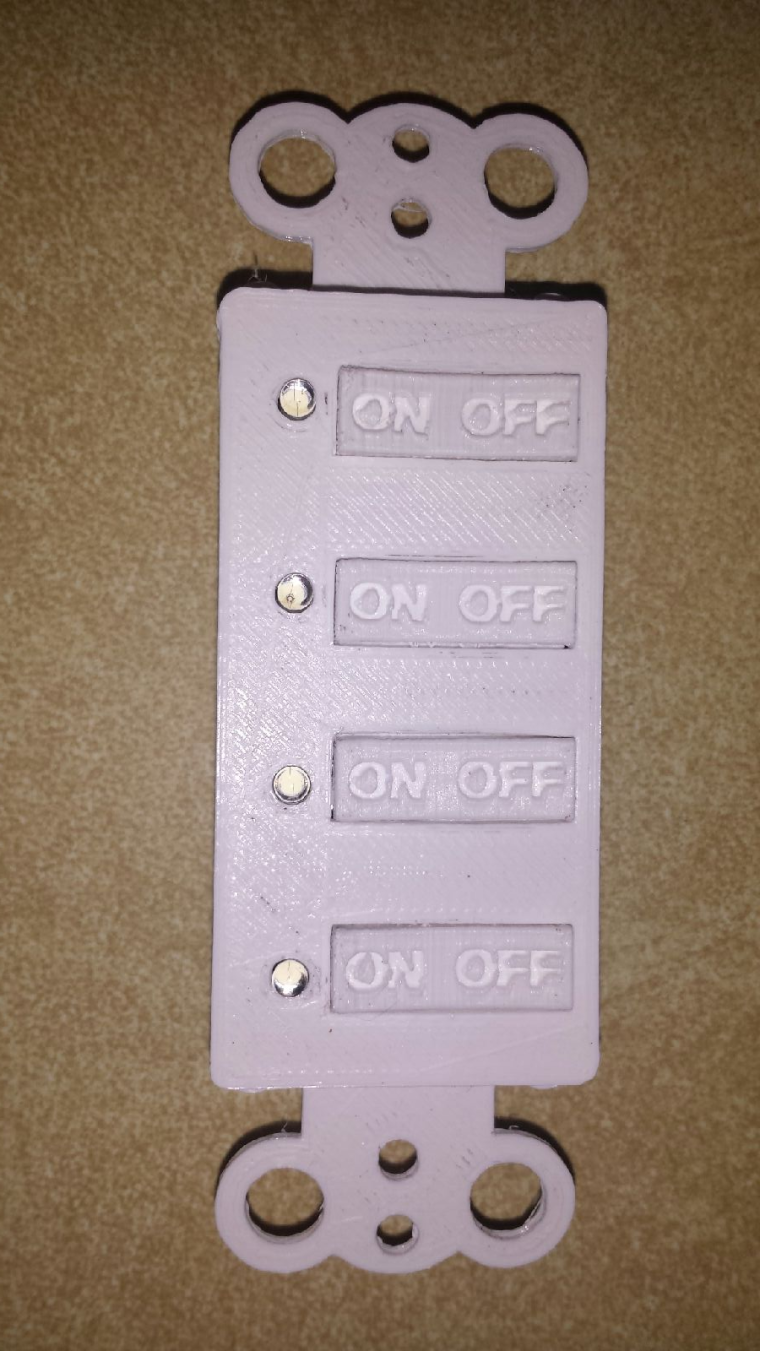
Because of having the rocker switches I have added one more piece to the design which is a rocker support for the switches to prevent both the on and off buttons for a switch to be activated simultaneously.
Here is a view of the prototype with the rocker support in place.
The LEDs that I currently have installed are 3mm white LEDs. I went with 10k resistors on them so as not to make them too bright since at full brightness these can be a bit blinding. I chose those because they are what I had available in my parts bin. Red or green LEDs might be a better fit for this. Choose a resistor value that gives whatever LEDs you choose suitable brightness as this can vary between LEDs.
For anyone interested I posted the 3D design files on thingiverse. Everything you need to make this switch board is posted there.
http://www.thingiverse.com/thing:2202434
Hello! It looks like you're interested in this conversation, but you don't have an account yet.
Getting fed up of having to scroll through the same posts each visit? When you register for an account, you'll always come back to exactly where you were before, and choose to be notified of new replies (either via email, or push notification). You'll also be able to save bookmarks and upvote posts to show your appreciation to other community members.
With your input, this post could be even better 💗
Register Login