Clearance, creepage and other safety aspects in "MySensors" PCBs.
-
I have been reading much lately about safety around PCBs and we also see a incresing numbers of PCBs @ openhardware.io which involves more than low DC power. With freeware CAD programs and cheap chinese pcb manufacturer alof of amatures like myself have the ability to create pcbs - in worst case not safe pcbs. This is what i gathered so far, so here we go:
Terms used
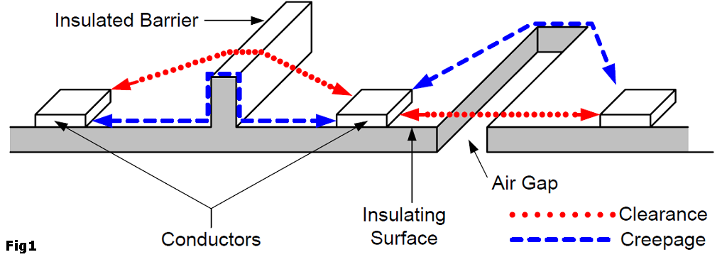
CREEPAGE
The shortest path between two conductive parts, or between a conductive part and the bounding surface of the equipment, measured along the surface of the insulation (Figure 1).
CLEARANCE
The shortest path between two conductive parts, or between a conductive part and the bounding surface of the equipment, measured through air (Figure 1).
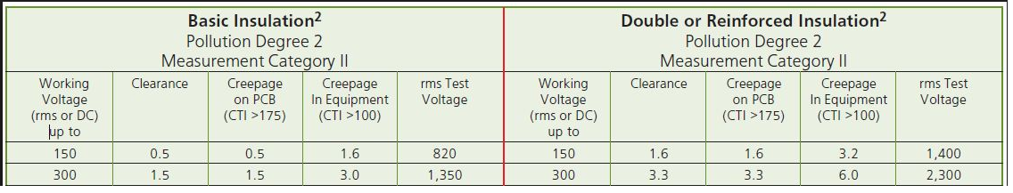
A minimum clearance table for 150 and 300v [Ref]
MATERIAL GROUP / Insulant
DIN EN 60664-1 (VDE 0110-1) divides the insulants according to their CTI values in four groups. These are:
Insulant I: 600 ≤ CTI
Insulant II: 400 ≤ CTI < 600
Insulant IIIa: 175 ≤ CTI < 400
Insulant IIIb: 100 ≤ CTI < 175
[Ref][Ref]Fr4 material (normal cheap-as PCBs) is normally 175 - 250CTI which is insulation material group IIIa. Ask your PCB house for your CTI value to be able to determine your material group.
POLLUTION LEVEL / Degree of contamination / Contamination level
The influence of the contamination is considered with the calculation of air and creepage distances by degrees of pollution.
- Contamination level 1
No contamination or only dry, non-conductive contamination occurs. The contamination has no influence. - Contamination level 2
Only non-conductive contamination occurs. However, occasional temporary conductivity must be expected as a result of moisture condensation. - Contamination level 3
Conductive contamination occurs; dry, non-conductive contamination which becomes conductive as a result of moisture condensation may also occur. - Contamination level 4
Impurities in the form of conductive dust, rain or humidity result in permanent conductivity.
[Ref]
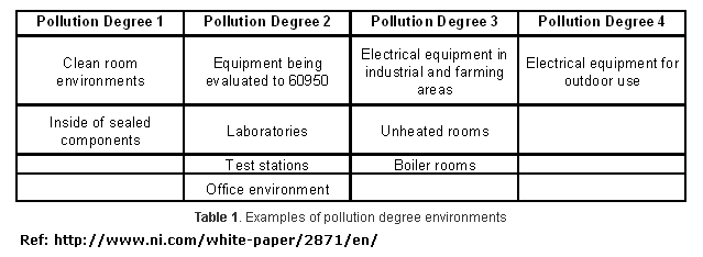
Note that if you put a PCB inside a sealed component you get pollution level 1
ISOLATION/INSULATION
This is one of the most important parts - by knowing your isolation group/type you need to have for safety you enter this into the creepage calculator to get your creepage distance.
“Isolation means that no direct electrical connection, or conductor, exists between two or more circuits or between circuits and accessible parts.” … “You use safety isolation to isolate hazardous, or "live," voltages greater than 30V rms and 42.4V peak or 60V dc from user-accessible SELV (safety extra-low-voltage) circuits. Safety isolation also minimizes the possibility of transient voltage arc-over or -through insulation to user-touchable circuits and enclosures.”[Ref]
Isolation and insulation
Users have access to voltage and current through touchable connectors, cables, and user-interface devices you find on most products. Voltages must be less than or equal to 42.4V÷60 peak dc to meet safe limits and to be SELV. SELV circuits are considered safe to touch and are double-insulated from hazardous voltages in case of a single fault. SELV circuits are commonplace and find use in product inputs/outputs and interconnection, such as logic circuits for printers, PC keyboards, and telecommunications devices.[Ref]There are five types of insulation: functional, basic, supplementary, double, and reinforced. Functional insulation is necessary only for the correct functioning of a product. Functional or operational insulation does not protect or isolate against electrical shock. Basic insulation is a single level of insulation that provides basic protection against shock. Supplementary insulation is an independent insulation that manufacturers apply in addition to basic insulation to reduce the risk of electrical shock in the event of a failure of basic insulation. Double insulation comprises both basic and supplementary insulation. Reinforced insulation is a single insulation system that provides electrical-shock protection equivalent to double insulation.[Ref]
Double, reinforced, and basic insulations are the most important insulation types for safety isolation. The minimum spacing requirements for safety insulation are double from hazardous live to SELV—for example, 3 mm on printed-wiring board. You use functional insulation between circuits to maintain the operation of the product, but you do not rely on it for safety isolation.
You should use basic insulation between hazardous voltage circuits, but the requirement depends on the applicable safety standard, function of the product, environment, and testing.[Ref]
When a breakdown can create a hazardous voltage on user accessible conductive parts (such as in case of insulation between mains circuits and low-voltage secondary circuits), a double or reinforced insulation is required. [Ref]
- Functional insulation is that which is only
necessary for circuit operation. It is assumed
to provide no safety protection. - Basic insulation provides basic protection
against electric shock with a single level;
however this category does not have a
minimum thickness specification for solid
insulation and is assumed to be subject to
pinholes. Safety is provided by a second level
of protection such as Supplementary
insulation or protective earthing. - Supplementary insulation is normally used
in conjunction with Basic insulation to
provide a second level of protection in the
event that the Basic level fails. A single layer
of insulating material must have a minimum
thickness of 0.4 mm to be considered
Supplementary insulation. - Double insulation is a two-level system,
usually consisting of Basic insulation plus
Supplementary insulation. - Reinforced insulation is a single-insulation
system equivalent to Double insulation. It
also requires a minimum thickness of 0.4 mm
for use in a single layer. [Ref]
How does this all come togheter?
The main question is how much space do I have to have between my traces/components on my PCB to make it safe? To know there are many calculators and tables online. One example is http://creepage.com/. To be able to use these calculators or to read the tables you need to figure out all this above.
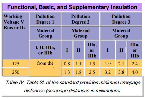
For example, we want to know the space between AC traces for a PCB that can be used in all enviroments.
If we enter this into a calculator for example creepage.com we get this:Insulation: Basic (we know it should be basic from above)
Pollution Degree 3 (for example, we want it to work in areas where condensation occurs)
Material Group IIIa or IIIb (we know it should be IIIb from above since its a normal FR-4 PCB)
Working Voltage 250 Vrms or VdcCreepage is 4.0 mm or 157.5 mils
We need 4.0mm between AC circuit to be on the safe side!Also if you have a AC (primary) hazardous side and a DC low voltage/SELV ciriut if we want to have a PCB within ALL limits we need to have reinforced insulation and then hits 8mm creepage between AC and DC side.
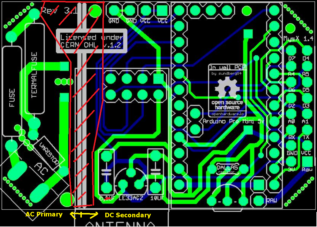
This is a example of a AC primary and DC secondary - but the distance is not 8mm between so it does not meet the reinforced insulation rules if you have a pollution degree of 3 or more.More about that here:
"PCB shall be constructed so that creepage distances are not less than those appropriate for the working voltage, taking into >account the material group and the pollution degree. Hence creepage distance depends of the CTI's material (Comparative Tracking Index) and pollution degree. European main standard are for Household Appliance (EN60335) and Information technology (EN 60950). As Reference value, in the worst case (Household appliance), for reinforced insulation between High voltage (220 Vrms) and low voltage (<50Vrms) on the same layer (top or bottom), you should an 8mm creepage distance between tracks (Fig. 1) as required for standard EN 60335-1-2, table 17. These distance are lower with better CTI and Pollution degree. If you can’t maintain these distances, you need a milling (cutting of material large at least 1.5mm) between the two points that do not meet the minimum safety distances (fig.2)." (Link)
Same general tip from this article
"A minimum of 8 mm separation between primary and secondary circuits also prevents problems. "
Conclusion
First of all its important to not mix AC high voltage and DC low voltage systems. These should be seperated with a "reinforced insulation".
Assuming MySensors nodes are normally in a normal indoor enviroment (Pollution dgr 2) we need to have atleast 5,0mm seperation between AC circuit and DC circuit if you are using 240v.Also the distance inside the AC circuit between the high voltage traces should be 2,5mm since this insulation is recommended to be "basic".
Conclusion 2
If you seal your box completely (see IP classifications) to avoid contamination from your environment you can design your board with distansens from pollution degree 1. This means pretty much clearance and creepage are the same. This means you need at 250v 0.56 mm [ref] between AC circuit (basic insulation) and 3.3mm between AC high voltage and DC low voltage. This has alot to do with material quality so I would add some extra space to be sure.
Conclusion 3
If you can’t maintain creepage distances, you need a milling (cutting of material large at least 1.5mm) between the two points that do not meet the minimum safety distances.
Disclaimer:
My disclaimer is still: I can not guarantee this info is safe! I have not made any professional tests. This is DIY and do not use this if you dont know what you are doing. It may hurt or kill you and damage your property. This thread is more of a question and discussion than a statement. Do not reference this thread. My goal is to figure out the safest way to make a MySensors PCB and the info above might not be correct.
Other Links
http://www.denverpels.org/Downloads/Denver_PELS_20090915_Aldous_Insulation_Coordination.pdf)
http://blog.optimumdesign.com/clearance-and-creepage-rules-for-pcb-assembly
http://learnemc.com/pcb-layout
http://www.itesafety.com/en_e3.pdf
http://sisko.colorado.edu/CRIA/FILES/REFS/Electronics/IPC_2221A.pdf
https://en.wikipedia.org/wiki/Insulator_(electricity)The end?
Please add your thoughts, questions and most of all knowledge to this thread. I will update the first post to make it easy to find info. Try to keep it in a amature language and avoid technical terms without explaining them.
- Contamination level 1
-
@sundberg84 - Thank you for spending your time to iron out all the information floating around the internet currently regarding this topic, to some it seems very overwhelming when researching to design a module, myself included struggle with this topic. Your time spent will help others save time and effort, again, thank you!
-
@Samuel235 - thank you. For some reason it interests me... :scream:
But its a hugh topic so please add thoughts or if you see I missed something. -
Will contribute as, when or if needed.
-
@dpressle -I have seen some tables with current in it. And also some overvoltage protection... but have not got my head around it yet. Also there is some trace WIDTH calculators and they are offcourse dependent on current. Do you have any good ideas where to start or any references?
Controller: Proxmox VM - Home Assistant
MySensors GW: Arduino Uno - W5100 Ethernet, Gw Shield Nrf24l01+ 2,4Ghz
MySensors GW: Arduino Uno - Gw Shield RFM69, 433mhz
RFLink GW - Arduino Mega + RFLink Shield, 433mhz -
@dpressle -I have seen some tables with current in it. And also some overvoltage protection... but have not got my head around it yet. Also there is some trace WIDTH calculators and they are offcourse dependent on current. Do you have any good ideas where to start or any references?
@sundberg84 I cant find it but i do remember there was reference somewhere, maybe its not that important if its not mentioned in most places.
-
Hey Sundberg84
First of all great article. When I look through it, I share the same interpretations of the clearance and creepage but again I also see something I not fully agree on
iF You are interrested in having a further discussion it could be great
Let me know
Thomas
-
Hey Sundberg84
First of all great article. When I look through it, I share the same interpretations of the clearance and creepage but again I also see something I not fully agree on
iF You are interrested in having a further discussion it could be great
Let me know
Thomas
@TNI I'm not a electrical engineer and this article is my learning and understanding along the way. I'm really interested in a discussion so I can learn more. Please post your thoughts!
-
@TNI I'm not a electrical engineer and this article is my learning and understanding along the way. I'm really interested in a discussion so I can learn more. Please post your thoughts!
@sundberg84 - I would take a little different approach. First of all I would find the product standard that my product needs to fulfill. Product standards do not always have the same requirments to determine the clearance (creepage the often have). I am working alot with IEC/EN/UL61800-5-1 and IEC/EN/UL60730-1. In 61800-5-1 the clearance shall be determined either by
- Impulse voltage
------This is based on the system voltage (phase to PE) and also the Over voltage cat. The value found is called basic. For reinforced next higher step shall be used. For Functional, the MOV determine the impulse. If it shall be one or two times below the basic insualtion. Normally PD do not affect the clearances at higher impulse voltages like 2.5kV, 4KV etc. The impulse voltage can be transfered into a distance in mm - Temporary Over Voltage
------ In 61800-5-1 it is determined by 1200+the line voltage. So for a 240V it would be 1440V. This can also be transfered into a distance in mm
. Working Voltage including recurring peak
------this has to be simulated, calculated or measured by the engineer. Values can also be transfered into distances in mm
Worst case of above determine the clearance value for the product
In 60730 only the impulse voltage is used to determine the clearance. They determine it the same as 61800-5-1. This is due to both uses 60664-1
Often the impusle voltage is worst case.
For creepage it is the working voltage (RMS or DC) that is permanent accros the two polarities. The voltage can also be transfered into a distance of mm.
Alot of the standards (also the two i have mentioned) have two columns dedicated for the PWB regarding creepage.
For creepage the standards (at least the two i have mentioned) state that if a creepage distance is less than 1mm it will become a clearance.
It is very difficult to write in this, so please add you email, I will prefer to write directly to You
Thomas
- Impulse voltage
-
@sundberg84 - I would take a little different approach. First of all I would find the product standard that my product needs to fulfill. Product standards do not always have the same requirments to determine the clearance (creepage the often have). I am working alot with IEC/EN/UL61800-5-1 and IEC/EN/UL60730-1. In 61800-5-1 the clearance shall be determined either by
- Impulse voltage
------This is based on the system voltage (phase to PE) and also the Over voltage cat. The value found is called basic. For reinforced next higher step shall be used. For Functional, the MOV determine the impulse. If it shall be one or two times below the basic insualtion. Normally PD do not affect the clearances at higher impulse voltages like 2.5kV, 4KV etc. The impulse voltage can be transfered into a distance in mm - Temporary Over Voltage
------ In 61800-5-1 it is determined by 1200+the line voltage. So for a 240V it would be 1440V. This can also be transfered into a distance in mm
. Working Voltage including recurring peak
------this has to be simulated, calculated or measured by the engineer. Values can also be transfered into distances in mm
Worst case of above determine the clearance value for the product
In 60730 only the impulse voltage is used to determine the clearance. They determine it the same as 61800-5-1. This is due to both uses 60664-1
Often the impusle voltage is worst case.
For creepage it is the working voltage (RMS or DC) that is permanent accros the two polarities. The voltage can also be transfered into a distance of mm.
Alot of the standards (also the two i have mentioned) have two columns dedicated for the PWB regarding creepage.
For creepage the standards (at least the two i have mentioned) state that if a creepage distance is less than 1mm it will become a clearance.
It is very difficult to write in this, so please add you email, I will prefer to write directly to You
Thomas
@TNI - Thanks for your input!
-
How do you find the right product standard for your product? Ie, a AC/DC PCB board?
-
So when you find your standard (I think I have been working alot with the standard for high voltage boards?) you find which creepage/clearance you need to work with? Can you give an example?
-Simulating and calculating by engineers isnt a option for us, this is open source hardware / DIY and this means "we do it on our own risk"... thats why im trying to gather as much info as possible - what would your recommendations be? -
I have noted Basic/reinforces above, but not connected the info to Impulse voltage. Can you give an example or my conclusions regargind Basic/reinforces isnt correct?
Thanks for your info Thomas! If possible I would be glad to keep the discussion here for others to see... thats what open source is all about :)
- Impulse voltage
-
@TNI - Thanks for your input!
-
How do you find the right product standard for your product? Ie, a AC/DC PCB board?
-
So when you find your standard (I think I have been working alot with the standard for high voltage boards?) you find which creepage/clearance you need to work with? Can you give an example?
-Simulating and calculating by engineers isnt a option for us, this is open source hardware / DIY and this means "we do it on our own risk"... thats why im trying to gather as much info as possible - what would your recommendations be? -
I have noted Basic/reinforces above, but not connected the info to Impulse voltage. Can you give an example or my conclusions regargind Basic/reinforces isnt correct?
Thanks for your info Thomas! If possible I would be glad to keep the discussion here for others to see... thats what open source is all about :)
@sundberg84 - Actually before finding the standard You would need to identify which area. Exmaple. In Europe there would be a directive (2014/35/EU is the new LVD directive, there are also for EMC, RED, ATEX etc.) When You have identified which directives You would need to comply with you can see which standards they have as harmonized (to fulfill the directive). If You are certifying for North America/Canada You use cULus (Listed) or cURus (recognized) and other countries have others like EAC for Russia, Belarus etc. and so on
But it can be a tough job finding the correct standard and even harder to find the end product standard (if your product is used inside another application). Example. A controller (certified according to 60730-1) which is used in 60335-1, 2-89 application (normally it is our customers who uses the end application standard). Here You would also need to check if the end application standard(s) have more severe requirments than 60730-1, if so You would need to adopt these into the certification of your product, else he/she might fail his certification. I am working with controllers. For industrial it is 61800-5-1 and for household it is 60730-1 or 60335-1 directly. It is important to check normative in the end product standard and see if the standard You are using is mentioned. Example. 60335-1 mentioned 60730-1 but not 61800-5-1. So the industrial standard cannot be used if You know that the end application would be 60335-1 and 2-?.
Fulfilling a standard is not only clearance and creepage but we will only look at that here
My examples are from 61800-5-1 (i cannot insert tables, that was why I would like mails, but I will just refere to the tables)
Clearance. As previous told this standard has 3 ways to determine the clearance. By Impulse Voltage (table 7) or by Temporary Overvoltage (Table 9) or Wokring Voltage including recurring peak (table 9).
For the determine by impulse You would beed to know the OVC (Over Votlage Cat). Fix installed is normally OVC III and plugable is OVCII. System voltage is (phase to PE voltage). So if You have a 3 phase 500V in a TN grid the system voltage would be 500/squareroot(3) = 288V. In table 7 the voltages are 150, 300, 600. So here the 300V (remember that interpolation is not permitted) at OVC III should be used (we only make for fixed installation). That would give an impulse of 4KV. So the basic insulation (phase to PE) shall withstand 4KV (and that is all components that are bridging the basic insualtion. Now the Functional insulation can be determined. By using MOV You can supress the Impulse and hereby choose 2.5KV or 1.5KV or even less. Depeding on what the MOV is rated. Remember that there is NO MOV to basic insualtion. If You have it can be there for two reasons. 1. EMC purpose or 2. spacing reduction. If You use it for spacing reduction it has to be monitored so if it is broken the user is informed. For reinforced (live parts to PELV or SELV) You would need one level higher whih is 6KV.
In table 9 these impulse values can be transfered into a distance in mm. T.O.W which is also determined from table 9 is 1200V plus the voltage so in this case it would be (between the phase) squareroot(2)*500 = 707V. This can also be calculated into a distance in mm (here interpolation is permitted). If this value is less than the value from impulse, the impulse voltage is used. For the WV including recurring peak You would need to measure it on an actual board in the worst case condition You allow (since You do not have the option to simulate/calculate). Value measured can be calculated in to a distance in mm (table 9). All values are compared and the worst case is giving the clearance.
Creepage. Table 10 is used. Table 10 has values for PWB and also other insulators. The PWB column (PD1 and PD2) can be used on PWBs. Requirement is that CTI > 175. If You have components that are designed by You (e.g. DC coils, RFI choke, SMPS transformers, BUS bars etc. these would have to comply with other insulators. This menas that CTI value of all parts within the component has to be evaulated. Example. According to table 10 @ 500V for PWB at PD2 you would need 2.5mm. If we design a RFI choke (between phases, R, S and T) there should be 2.5mm bwtween the phases. Other insulators have 3 groups, I = CTI >600, II = 400<CTI<600 and IIIa/b = CTI less than 250. So if distance on the choke shall be 2.5mm the piolymeric used around the core shall have a CTI of 600, if we choose a polymeric with a lower CTI the creepage would be either 3.6mm or 5mm (taken at 500V in table 10). I cannot tell You why, personally I think it is crazy that CTI on PWB of 175 = 2.5mm and CTI of polymeric on choke of 175 = 5 is not the same. Table 10 is for functional and basic insulation. So if You would need to find the value to either PELV or SELV (reinforced You would need to multiply the distance You find by 2.
Remember that the standard also state that a creepage cannot be less than a clearance.
Thomas
-
-
Hello @sundberg84 , this is a topic that I have made some research myself, I wanted to make my PCB the safest possible. One question that I would like to put you is the development in KiCad (don't know if you use it), but one thing that I KiCad doesn't take into account, is the "air gap". You put in your design rules that you what to have 8mm of isolation, and if you are required to have less, by layout constrains, and put a air gap in between pads to raise the creepage, Kicad will still give you a error on the design verification. What do you do in this situations? Ignore the errors?
Another thing that you must also take into consideration is the cooper width, this also is very important.
Thank You and nice work
@soloam - hi!
Thanks for your input. Yes I use KiCad.
Yes, clearance is only calculated in the designrules and not creepage and that can be a issue. I have seen some posts on KiCad forum about this. In normal situations i try to avoid slots ("air gaps") as much as I can but when I add them, I need to manually calculate the creepage with the ruler och creating a track along the shortest point-point and measure that track length.From one of the sources:
Clearance is measured in air (line of sight), so there is little that can be done at the layout level to reduce the required spacing. Careful placement does make a difference, but the more significant reductions in spacing can be achieved by using insulating materials and, when possible, by double-sided assembly.
Clearance is generally less than creepage so I always try to set my designrules for the creepage values. If they are impossible to maintain... I try to redesign first and second i add slots and ignore the error after manually measured the creepage.
-
That is what I do, I create a rule to pads with creepage and rely on my calculations. I'm rebuilding my current switch board to make it safer to use in more polluted environment, I need to use one outside (in a box, but better safe than sorry), and in a bathroom.
I think that the main problem with the pads and traces spacing is the design constrains. I need to keep it in a 5x5 cm board and that is not easy, especially when you have a AC and DC circuit! I never considered the distance between AC and DC, and that is the main reason for me to rebuild my boards. After reading your post I made some researches, and I found that I had a design problem. Like you stated, I'm not a electrical engineer, and we are always learning :)
-
That's some impressive research. Personally I think you don't have to be that hard on yourself when creating hobbyist equipment and devices. With that I mean you might not have to build the device according to the most rigorous safety level. It of course depends on what you are building and how it is going to be used. (Disclaimer; I have a degree in electrical engineering, but I haven't been working with this stuff actively, only as a hobby).
Now there is another aspect also (that is mentioned in this thread). There are competing standards that might or might not be applied in various countries. And most importantly, if you build a device for commercial use, you have to follow the standards in your own area. This might take years of research and work and isn't possible for the hobbyist.
There are of course the general IP classes. If you build a device for IP level 20, the standard says:
"Parts in mains voltage potential should have at least a 6 mm aerial distance and 3 mm insulated distance to conductive parts that the user of the appliance can touch"
This means for instance the distance between a circuit board with mains voltage and the chassis.
Then there is IPC-9592 for power conversion devices. It defines a safe creepage distance as:
0.6 + voltage * 0.005 = creepage distance in mm.
For instance for 250V that would be 1.85 mm, which I think is quite a good rule of thumb for hobbyist applications. That is around Pollution degree 2, II, in your table (which was from DIN EN 60664-1?).
Then there is UL 6500, which is an older standard for audio equipment. They define "The least safe distance in mm between the two differentials in voltage" as:
d = 10^(0.78log(U/300))
Where d is in mm and U in volt. Thus 250 V would be 0.87 mm. That seems rather low, though, if comparing with other standards.
As has been already said in this thread, you have to look at what standards you need to adhere to. But for hobbyist stuff and for devices you build for yourself, you yourself ultimately have the responsibility. And maybe you don't have to follow the most rigorous standard.
Hopefully people that build commercial devices have this all covered. I couldn't imagine that they copy a design from a hobbyist board and create a commercial device based on that. Not when it involves mains voltage. Low voltage stuff is maybe another matter.
@JohanH - thanks for your reply! I also hope and think people who build commercial products have knowledge of this :)
But as a hobbyist, there are two ways to go - either you dont have to care or go bare minimum, if something happens its your own fault, or you can try to make is as safe as possible.My idea was never to make this thread a information source for a commercial product. I wanted to try to make my own products as safe as possible since I have children around. With that in mind, i want to be on the safe side of things so some things i use from here might be exaggerated.
But my PCB (HLK-PM01 breakout) is working great, and I feel safe. I have had it outdoors (under roof covered in IP5* box, -20 to +30 aprox) and its been working for me for a couple of years now. Better than I had before, when i just stripped an old fake samsung charger.
/Andreas
Hello! It looks like you're interested in this conversation, but you don't have an account yet.
Getting fed up of having to scroll through the same posts each visit? When you register for an account, you'll always come back to exactly where you were before, and choose to be notified of new replies (either via email, or push notification). You'll also be able to save bookmarks and upvote posts to show your appreciation to other community members.
With your input, this post could be even better 💗
Register Login